
Abstract
Wireless sensor networks (WSNs) have been widely recognized as a promising technology that can enhance various aspects of infrastructure monitoring. Typical applications, such as sensors embedded in the outer surface of a pipeline or mounted along the supporting structure of a bridge, feature a large-scale linear sensor arrangement. In this paper, we propose a new bidirectional wireless communication scheme, based on the high-level data link control (HDLC) standard, for devices with short-range transmission capabilities for linear sensor topology. By applying for the first time a standard data layer along with a time division multiple access (TDMA)-based medium access control (MAC) and time synchronization technique specifically designed for the linear topology, we address the interoperability problem with guaranteed energy efficiency and data link performance in linear sensor topology. The proposed Wireless HDLC supports half-duplex communication, point to point (peer to peer), and multipoint networking.
1. Introduction
The existing applications of WSNs span a very wide range, including remote system monitoring and control, fraud detection, environmental monitoring, and so forth. So far, little focus has been given to low-power WSNs for linear topologies. Some papers present linear wireless networks for bridge [1], pipeline [2], or overhead transmission lines [3–5] application. For instance, real time monitoring of power cables thermal conditions and ambient conditions such as temperature and humidity could result in higher dynamic rating of transmission lines and will increase the utilization of their power-carrying capabilities [6]. However, the systems described in these works are proprietary solutions, following no particular standard for communication and arising interoperability problems when they are used. Due to their linear geometry, direct transmission from data source to sinks is usually not practical because the sensor nodes (SNs) have a limited communication range and data sources are generally far away from the sinks. Therefore, a multihop network is a good choice for data routing, and clustering topology is appropriate to achieve network scalability [7]. Topology design, power usage minimization, and installation cost are very important for successful deployment of linear WSNs while meeting the application requirements. This paper proposes a new WSN technology based on standard HDLC protocol for long-term continuous monitoring of large-scale linear infrastructures so that efficient monitoring and management systems can be established.
As shown in Figure 1, wireless multifunctional SNs are installed on the critical components of large-scale infrastructures such as bridges, pipelines, or power cables, using linear topology. However, the power supply constraints of the WSNs deployed in these infrastructures pose great challenges in energy consumption. Hence, there is a need for reliable and low-power WSNs for linear networks capable of being powered through harvesting devices for long-term monitoring. Therefore, WSNs based on IEEE 802.15.4 standard for low-power wireless transceiver technology need to be used [8]. Generally, the transmission range of the nodes is assumed to be 10–100 m with data rates of 20 to 250 kbps [9]. Hence, large network and multihop communication are required so that nodes relay the information to the data collector, that is, the sink. Moreover, these networks have to combine power and routing awareness, communicate power efficiently through the wireless medium, integrate data with networking protocols, and promote cooperative efforts of SNs [10].

Wireless linear network as a chain of low-power sensor nodes (SNs) deployed in linear topology.
Several wireless standards such as ZigBee [11], WirelessHART [12], 6LoWPAN [13], and SP100.11a [14] formed on top of IEEE 802.15.4 standard, which specifically address the typical needs of wireless control and monitoring applications have been actively pushing the application of wireless technologies in industrial measurement and control applications. The ZigBee protocol is the driver for the development of the 802.15.4 standard and uses the IEEE 802.15.4 PHY and MAC layers but it defines the network and application layer. The WirelessHART and ISA100.11a also use the 802.15.4 PHY but define their own MAC and network and application layers [15]. Following the OSI reference model, it specifies the network and transport layer and use the 802.15.4 PHY and MAC sublayer of the data link layer [16]. Generally, the network topology of these standards is designed as a mesh network and enables application-specific solutions to be developed for WSNs. However, except for the WirelessHART network where each device can act as a source or a router, in the other standard networks, dedicated routers nodes are necessary to provide communication between source nodes and sink. Moreover, the number of network hops allowable within these standards is limited. The maximum distance from a node to the sink that is allowed by the WirelessHART is of 4 hops, by ZigBee and ZigBee PRO is of 10 hops and 30 hops, respectively, and ISA permit up to 20 hops. The theoretical number of hops limit in a 6LoWPAN network is 255 (8 bits hop limit field). However, 6LoWPAN networks with this specification have not been reported in the literature to date [16].
These limitations are very important for WSNs deployed in large-scale infrastructures, where the number of hops is assumed to be in order of hundreds and each node is both source and router. In this framework, we present the implementation and evaluation of a bidirectional wireless communication schema for linear IEEE 802.15.4-compliant WSNs based on HDLC standard [17] (Wireless HDLC). Table 1 illustrates the capabilities of the proposed Wireless HDLC network in comparison to the existing standard WSN solutions.
Comparison in terms of devices power consumption, hops limit, and topologies for existing standard protocols and the proposed Wireless HDLC.

The Wireless HDLC adopts the IEEE 802.15.4 PHY layer but defines a new TDMA-based MAC, network and transport layers based on HDLC standard. The issue regarding synchronization of nodes throughout the network is addressed by applying any of the time synchronization techniques available such as TPSN (timing-sync protocol for sensor networks) [18] or PTP (precision time protocol) [19]. These techniques may exchange timestamp messages to synchronize distributed clocks in a network while meeting the power usage and bandwidth minimization required by WSNs. The chain of short-ranged wireless sensors creates a virtual wired link by means of an ad-hoc network. The system does not require complex routing techniques. The proposed Wireless HDLC supports half-duplex communication providing a bidirectional link between the SNs and the sink. The communication is done in rounds, one time from the sink node to the last node in the network (end node) and one time from the end node to the sink. The bidirectional link acting as a virtual conveyor belt can be used to collect data from different sensors along thepath or send data from the base station to different sensors in the network. The data from multiple devices is encoded as HDLC frames and is collected in the available space of the IEEE 802.15.4 standard packet up to a maximum size of 125 octets [8]. In this way various nodes can send variable length packages in one communication round of the transmission grid, following a standard form.
The paper is organized as follows. In Section 2 we review some existing related works. Section 3 describes the Wireless HDLC protocol stack layered architecture based on HDLC standard. Section 4 validates our design by demonstrating the Wireless HDLC network. Finally, this paper is concluded and the future work is presented in Section 5.
2. Related Work
Wireless sensor network has been the focus of extensive study recently [20–24] proposing a wide variety of algorithmic and communication protocols solutions. Most studies are focused on generic WSNs which assume that sensors are deployed randomly and abundantly in the same area and perform the same function. The smart features envision in the roadmap for research and development of the next generation WSNs, as digitalization, flexibility, intelligence, and customization deal with the interoperability problem in order to allow plug-and-play capability to accommodate progressive technology upgrades with hardware and software components. The plug-and-play capability for low-power WSNs can only be achieved by applying standard technologies such as ZigBee, WirelessHART, 6LoWPAN, or ISA SP100. Although, these standard solutions give support for mesh networking and can be used in a wide range of applications such as home automation, smart energy, building automation, industrial automation, and personal health care, they are not optimized to work in large-scale areas. Due to the geometry of large-scale infrastructures, WSNs with linear topology have to be used.
However, the design of these WSNs pose several challenges due to their linear nature, limited energy source, robustness to dynamic environment, and scalability to numerous number of sensor nodes. What follows describes the WSN design challenges for an efficient communication in this environment.
2.1. Energy Consumption
A wireless module is equipped with a limited energy source (i.e., battery, harvesting and device) and hence has an energy consumption capacity and lifetime that is dependent on that source. In a WSN, each node plays two separate and complementary roles: it can originate data and also has to route data. Moreover, if a few nodes deplete their energy resources, it can cause significant topological changes and might require rerouting of packets and reorganization of the network.
2.2. Operating Environment and Fault Tolerance
WSNs for large-scale infrastructures have to be designed with extreme environments in mind. The environmental interference but also physical damage or a depleted energy source may cause an SN to fail. However, the failure of a single node should not affect the overall operation of the network.
2.3. Scalability and Network Topology
Depending on the infrastructure's length and the number of points of interest, the quantity of SNs deployed in these WSNs may be in the order of hundreds. Therefore, WSN protocols have to be designed to work with these large numbers of nodes. Also a major challenge is the deployment of these SNs to minimize the cost of deployment under the constraint of coverage, connectivity, and link outage probability so that the phenomenon of interest can be monitored efficiently. Moreover, additional SNs can be redeployed at any time to replace the malfunctioning nodes or due to changes in task dynamics.
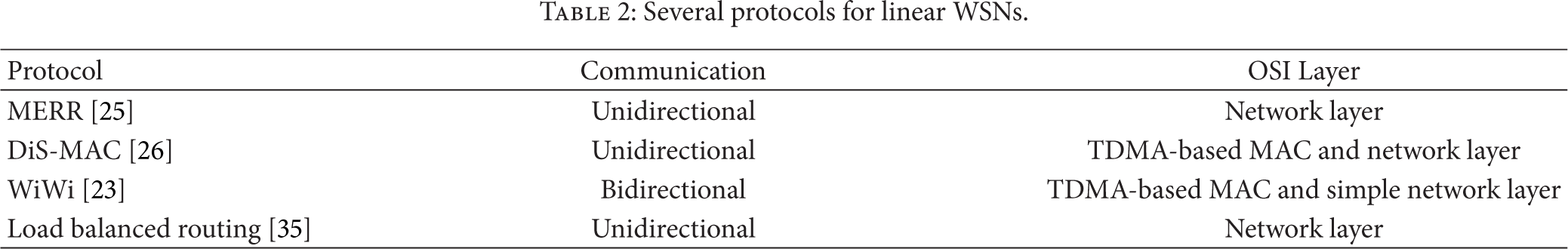
Between all these difficulties, the topology is maybe the most important challenge facing the development of WSNs for large-scale infrastructures. Topology is important for any type of network because it has a great impact on the communication performance of the system. In the literature we can find some examples of algorithms and protocols that are specifically aimed for linear topologies. In [25] Zimmerling et al. proposed the Minimum Energy Relay Routing (MERR) algorithm. Its aim is to minimize the routing path from every node to a common control center. In particular that work covers the routing problems of the special case of a linear network where nodes are located close to their neighbors. The Directional Scheduled MAC (DiS-MAC) [26] is another protocol that has been developed for WSNs that shows a linear topology. With DiS-MAC, Karveli et al. a fail tolerant unidirectional routing protocol for linear network is proposed. In [23] the Wireless Wire (WiWi) protocol is described. This work proposes a bidirectional wireless communication schema with deterministic properties in terms of throughput and latency over a strip of pervasive devices with short-range transmission capabilities. The system is synchronous and fault tolerant and can provide support for an end-to-end communication.
As shown in Table 2, both MERR and load balanced routing are focused on routing problems without considering the underlying MAC protocol or the transport layer. The DiS-MAC protocol is focused on TDMA-based MAC protocol and also on routing problems in the linear network but suffers from being unidirectional. The WiWi protocol defines a TDMA-based MAC protocol and it provides bidirectional communication over a single RF channel. However, in this protocol, power consumption is not considered, and the SNs have to be in active mode for long periods of time. Moreover, compared to standard technologies such as ZigBee, WirelessHART, 6LoWPAN, or ISA SP100, these protocols have a significant drawback providing incomplete architecture and no standard is followed. In next generation WSN's vision, large, integrated, complex systems require different layers of interoperability, from a plug or wireless connection to compatible processes and procedures [27].
Several protocols for linear WSNs.
Although it bears many similarities with these works, such as routing techniques, the implementation of Wireless HDLC network differentiates itself from them in many other aspects. In particular, different from the protocols proposed in these papers is that HDLC has been widely implemented in cable networks because it supports both half-duplex and full duplex communication lines, point to point (peer to peer) and multipoint networks and switched or nonswitched channels. The HDLC protocol resides with layer 2 of the OSI 7-layer communication model, the data link layer. However, it offers three different modes of operation supporting a reliable and orderly transfer of packets in a distribute network (transport layer) and specifies the types of stations for data link control. The HDLC is essentially a centralized wireless network which uses a central network manager, the primary station, to provide routing and communication schedules to meet the requirements of wireless applications.
The design of Wireless HDLC architecture is based on the requirements of WSNs for large-scale infrastructures, meeting the challenges for an efficient communication in these environments and the need for standard solution for next generation WSNs applications. In the proposed Wireless HDLC network, frames of many SNs can be transmitted in one IEEE 802.15.4 standard packet traveling in the linear networks from the sink node to the end node and from the end node to sink node. This allows data collection and control of individual or groups of low-power field devices deployed with linear topology.
3. Detailed Description
This section presents a unique vision for the WSNs with linear topology in which the wireless network provides half-duplex communication and point-to-multipoint connection. Also, following the OSI reference model, the protocol stack layers of the Wireless HDLC networks are described. In Figure 1 the proposed Wireless HDLC network with a central network manager (sink) and SNs with routing functionality capable of building up the linear link is illustrated.
3.1. Data Link Layer
The Wireless HDLC protocol stack is designed as a synchronous multihop communication scheme and uses a TDMA-based MAC protocol that provides collision-free multiple access. The decision to focus on the TDMA approach arises largely from the fact that the energy consumption is significantly lower than the contention-based due to collision-free communication and minimization of idle listening. The operation of TDMA-based MAC is divided into sequences of phases as depicted in Figure 2.

TDMA-based MAC protocol for Wireless HDLC networks.
The sequences of phases consist of a network set-up phase and a communication phase. The set-up phase is designated for updating the sensor model at the sink. The sink informs each node about slots in which it should listen to other nodes’ transmission and about the slots, which the node can use for its own transmission. Once the linear network is built, the system enters into the data transfer phase. The data transfer phase is divided into up-session and down-session. Each session consists of a data transmission/reception period and an idle period. The up-session provides time slots for each node, starting with the sink up to the last node in the network. The down-session provides time slots for each node, starting with the last node to the sink. Assuming that there are N nodes within a network then the session's period consists of exactly N slots. The slot duration is the time required to transmit two times a maximum sized IEEE 802.15.4 packet (10 ms) and the duration of idle period depends on the network communication rate. Any node that does not have data to send is assumed to be a repeater. During the data transmission/reception period, each node turns on its radio and sends/receives its data to/from his neighbor over its allocated slot-time and keeps its radio off at all other times.
Time synchronization is a fundamental issue in TDMA protocol and for this, accurate timing is ensured by applying synchronization techniques such as PTP protocol [19]. By exchanging timing messages, within HDLC frames, the network may achieve high synchronization precision, in order of microseconds or submicroseconds, as an exact measurement of the transmission and reception times.
The data traveling in the Wireless HDLC network is a collection of HDLC frames (superframe) transmitted in an IEEE 802.15.4 packet as illustrated in Figure 3. Each HDLC data is organized into frames using a frame delimiter, or flag, which is a unique sequence of bits

Schematic view of HDLC superframe.
The data transfer transactions in the Wireless HDLC network are designed based on HDLC specifications. The HDLC offers three different modes of operation, the Normal Response Mode (NRM), Asynchronous Response Mode (ARM), and Asynchronous Balanced Mode (ABM) [17]. However, because of the linear nature and the requirements of Wireless HDLC only NRM and ABM modes are used.
The NRM is a master-slave mode and is used to coordinate the data transfer between the network nodes and the sink. In NRM, the sink (primary station) gives permission for each network node (secondary station) to speak. The secondary station can only transmit a response when, and only when, it is instructed to do so by the primary station. This transmission from the secondary station to the primary station may be one or more information frame. Once the last frame is transmitted by the secondary station, it must wait once again for explicit permission to transfer anything from the primary station.
In Figure 4, an example of Normal Response Mode (NRM) data transfer is described for the wireless multipoint line using the P(oll)/F(inal) procedure. In this example, a primary station (sink) and 5 secondary stations (SNs) on a multipoint line are illustrated. The sink sends out its data in the TDMA up-session (1) with

Data transfer in Wireless HDLC multipoint line using poll/final procedure.
The ABM mode allows the data transfer between two peer devices (combined stations). The combined station acts as both a primary and a secondary station. The ABM is used as data transfer transaction mode between neighbor nodes in the set-up phase and also in the communication phase, when a node transmits rescheduling or energy information to its neighbors.
3.2. Network Layer
In the literature, many routing algorithms and protocols are reported for WSNs. As reported by Singh et al. all major routing protocols proposed for WSNs are broken down into seven categories: location-based protocols, data-centric protocols, hierarchical protocols, mobility-based protocols, multipath-based protocols, heterogeneity-based protocols, and Quality of Service (QoS)-based protocols [28].
From the literature review of the routing techniques and based on the network topology and challenges of the Wireless HDLC, the hierarchical protocol Power-Efficient Gathering in Sensor Information Systems (PEGASIS) [29] was chosen. The main reason for adopting this routing protocol was that in Wireless HDLC, where wireless network is constituted by low-power SNs distributed along a strip, the PEGASIS can form a chain from SNs so that each node transmits and receives data from a neighbor. PEGASIS protocol provides the mechanism for sensors to transmit data to their closest neighbor until the end of the network is reached. In the PEGASIS routing protocol, the construction phase assumes that all the sensors have knowledge about their positions and use a greedy approach. In the Wireless HDLC, the positions of the sensors can be determined through the rules such as best link quality or lowest delay. When a sensor fails or dies due to low battery power or when it has run out of energy, the chain is constructed using the same greedy approach by bypassing the failed sensor.
3.3. Transport Layer
The transport control protocols for WSNs are important for reliable data dissemination and energy-conservation. Generally, transport control protocols may include two main functions: congestion control and loss recovery [18]. In order to weaken congestion, the transport layer can use end-to-end mechanism like TCP or hop-by-hop approaches. However, the end-to-end mechanism, which is based on acknowledgments and end-to-end retransmissions, imposes significant overhead for the implementation of these solutions in WSNs. Moreover, hop-by-hop approaches can control congestion with less ongoing packets in networks, while it needs to change the behavior of each node on the way from source to destination. Due to bad quality of wireless channel, sensor failure, and/or congestion, the transport layer should manage the packet loss and data from SNs should be reliably transferred to the sink. Also, the commands and queries from sink should be reliably delivered to the target SNs to assure the proper functioning of the WSNs.
This transport layer aims to address both the reliability and congestion problems using a mixed solution between end-to-end mechanism and hop-by-hop approach through HDLC supervisory frames. Between a pair of nodes, which transmit data accordingly to PEGASIS routing technique, in case of packet errors, each node performs hop-by-hop recovery to fetch the lost packets from neighbor nodes. An SN tries to transmit a package to its neighbor until it receives a Receive Ready (RR) supervisory frame, which acknowledges the reception of this package. Using the TDMA-based protocols explained above, the number of retries is limited by the time slot period and the size of the superframe. To obtain a good compromise between the hop-by-hop reliability, the link delay, and the energy consumption in the proposed WSN, the transmission time slot was set to 10 ms permitting two reties of a maximum sized IEEE 802.15.4 packet.
However, end-to-end reliability cannot be maintained in all cases even though hop-by-hop reliability is ensured. Therefore, an end-to-end mechanism is also used for the data transfer between SNs and the sink as illustrated in Figure 5. This method is based on the Selective Reject Automatic Repeat Request (SREJ ARQ) technique provided by HDLC protocol. As shown in Figure 5, the SREJ ARQ technique uses the Send Sequence Number (NS) and the Receive Sequence Number (NR) to control the correct data exchange between the sink and a Sensor Node (SN).
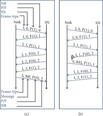
HDLC operation: (a) normal two-way data exchange and (b) selective reject ARQ.
3.4. Application Layer
Generally, the application layer provides necessary interfaces to the user to interact with the physical world through the WSN. Hence, the role of the application layer is to abstract the physical sensors and topology of the WSN for the applications. The large variety of available sensor types complicates the integration of sensors into monitoring systems. Therefore, the use of standard interfaces and data encodings such as IEEE 1451 Smart Transducer Interface Standard [30, 31] and time synchronization standards such as IEEE 1588 PTP protocol [17] is recommended. Hence, we propose the use of standard applications, which can be easily implemented on the Wireless HDLC network, in order to hide the underlying layers, the network communication details, and heterogeneous sensor hardware from the applications built on top of it.
Figure 6 illustrates the proposed half-duplex communication model suitable for low-power WSN and the handling of downstream and upstream data flows. The upstream data flow is generated by the sink and flows up to the last node in the network. The downstream data flow is generated by the last node in the network and starts when the upstream flow reaches this node. In this way a two-way communication cycle is generated which repeats itself along the time based on a network communication period. This data flow has a strict staggered pattern: each node will calculate the trigger time for receiving and transmitting a time slot based on the total number of hops. The hop-by-hop approach in a pair of consecutive nodes is also depicted in Figure 6; a node transmits an IEEE 802.15.4 packet to the next node and waits for a message to acknowledge this. With a transmission rate of the 802.15.4 Standard 2.4 GHz physical layer of 250 kb/s, a message with the maximum size of 127 bytes (125 bytes payload + 2 bytes PHY dependent for IEEE 802.15.4) transmitted between pair nodes in 4000 us and with an acknowledge timeout of 1000 us is allowed for one retransmission. Depending on the synchronization accuracy, the pairs of sensors will use a time offset for the transmit-receive process to avoid loss of messages.

Bidirectional communication for low-power Wireless HDLC networks.
The upstream IEEE 802.15.4 packet transmitted by the sink node contains HDLC frames with data, commands, or timing information to SNs. The downstream packet is a collection of HDLC frames with the responses from SNs to the sink commands. If an SN does not receive any command from the sink node it will work as a router and will transmit the downstream packet to the next hop.
4. Implementation and Performance Evaluation
This section starts by introducing the hardware platform we use to evaluate the Wireless HDLC and then offers a description of its implementation and provides the results of our proposal.
4.1. Hardware Platform
We base our implementation on the XBee and XBee-PRO 802.15.4 OEM RF modules [32] provided by Digi. The modules contain the MC13211 platform which incorporates a low-power 2.4 GHz radio frequency transceiver and an 8 bit Freescale HCS08 microcontroller [33]. The modules are driven by a 16 MHz crystal source and contain an internal event timer block of 24 bit clocked at a rate varying from 15 kHz to 2 MHz used to maintain the SNs time and synchronization.
Freescale provides for this platform a simple IEEE 802.15.4 physical layer library in ANSI C used to build our proposed protocol stack and the new firmware for XBee modules. A prototype design, using the XBee module, has been developed for the Wireless HDLC. The prototype is equipped with a harvesting device as power supply [34]. Also, the board includes 8 ADC channels of 10 bit, one SPI port, and a RS232 interface. Hence this platform can be equipped with various sensors to monitor phenomenon of interest.
4.2. Protocol Stack Design
Figure 7 describes the overall design of the Wireless HDLC data link layer which consists of four major modules: timer, TDMA function, HDLC framer, and the state machine. The timer module provides accurate timing to ensure the system operates correctly. The timer module has been designed as a real time clock capable of providing accurate triggers for wake-up, measure, receive, or transmit states of the SNs and also to keep the 10 ms time slots in synchronization. To keep the synchronization of the timer module, a simplified PTP protocol [34] is used to exchange timing messages in the network. This protocol provides methods to implement transparent clocks in multihop networks, to calculate the delay time, and to adjust the offset between the master clock and slave clocks. With this method, each SN can also synchronize their source clock using the trim capability of the 16 MHz crystal, which reduces their drift with the master source clock. Using the 24 bit counter clocked at a rate of 2 MHz, the nodes are able to obtain synchronization accuracy in the order of a microsecond.
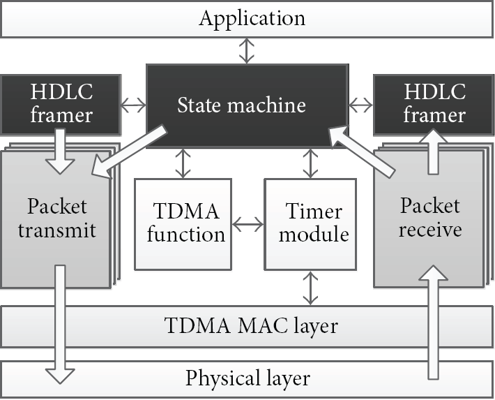
HDLC protocol stack architecture.
The TDMA function determines the usage of time slots for communication. This module uses a schedule to calculate the number of time slots between the downstream and upstream data flows for each sensor according to the number of nodes in the network. It also calculates the time for the next communication cycle based on network communication period. Every event that can affect the time scheduling will cause the TDMA function to reassess this scheduler.
The functionality of the HDLC framer is to decode the received messages in order to get the relevant information for the SN and to generate and add HDLC frames to the transmitted messages. If an SN receives an HDLC frame from the sink node with his unicast address, it will delete the frame from the IEEE 802.15.4 packet and will retransmit the remaining package. Next, in the downstream data flow, the node will add the response, for the sink query, to the received superframe and it will transmit the new package to the next node in the network.
The state machine is responsible for sending and receiving a packet over the transceiver. Based on the TDMA triggers, it executes the transaction in a slot and uses a light implementation of PTP protocol to adjust the timer module.
4.3. PTP Protocol over Wireless HDLC
The PTP standard specifies a clock synchronization protocol applicable to distributed systems consisting of one or more nodes communicating over a network. The protocol provides a mechanism for synchronizing the clocks of participating nodes to a high degree of accuracy and precision. However, a full implementation of this protocol as is specified by the IEEE 1588 standard is not suitable for low-power WSNs. The main challenge is that the IEEE 1588 messages size is more than the maximum size allowed in IEEE 802.15.4. Therefore, a light implementation of this standard is proposed for Wireless HDLC networks. The wireless implementation of PTP protocol is built on top of HDLC protocol consisting of PTP devices including ordinary clocks and transparent clocks. Figure 8 illustrates the basic pattern of synchronization message exchange in the linear topology of Wireless HDLC.

Synchronization messages exchange for linear topology. The slave communicates with the master through transparent clocks.
The timestamp information obtained with this exchange of PTP messages may be used to compute the offset of the SNs (transparent clocks) with respect to the sink (master clock) and the mean propagation time of messages between the two clocks. Considering that the master-to-slave delay is equal to the slave-to-master delay and by using the time information in the four messages illustrated in Figure 8, these quantities can be calculated from the measurement values 
The general format of the PTP messages codified as an HDLC frame is shown in Table 3 and has a size of 14 bytes (8 bit address) or 15 bytes (16 bit address).
PTP message fields in HDLC frame.
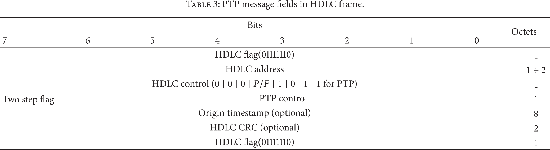
Each PTP message starts and ends with an HDLC flag. The PTP messages are defined as unnumbered frames (U-frames) using a nonstandardized control value of the HDLC control field (
The histogram presented in Figure 9 represents the time deviations between the sink node and the first four consecutive SNs in Wireless HDLC. The mean time delay is 1144.30 ns with a standard deviation of 1082.27 ns and a maximum value of 4506 ns.
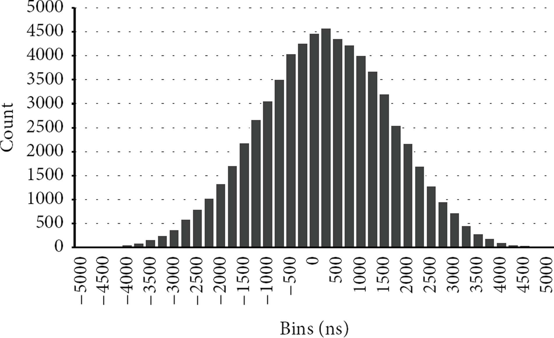
PPS signals delay histogram in linear network between the four consecutive SNs.
The obtained results show that through this technique we are able to obtain microsecond precision with efficient energy saving. Hence the SNs can maintain their TDMA-based protocol with very high accuracy, providing collision-free communication and minimization of idle listening.
4.4. Network Demonstration
Based on the prototype stack, we develop a linear self-powered WSN, with the aim of building a demonstration network for monitoring the environmental and infrastructure parameters. The demonstration network contains one sink (master) node and seventeen SNs. The SNs have been designed as alert nodes to detect critical events and generic monitoring nodes to measure different parameters such as infrastructure components temperature, ambient temperature, and humidity. The SNs in the network have been deployed with a gap varying from 50 m to 100 m that can cover approximately 1.2 km of infrastructure as shown in Figure 10. Each node can communicate with two nodes to the left and two nodes to the right. If, for example, node 10 is damaged, node 11 can still send the downstream data flow through node 9. The SNs have been programed to respond to different types of commands like “take sample,” “get calibration,” or “get capability.” To reduce the amount of information transmitted over the air, these sets of commands have been encoded in an 8 bit length format. If a user or the master node transmits the “take sample” command in the upstream data flow to different nodes using unicast addresses or multicast addresses, these sensors will put their raw measurements in the downstream data flow.

Each node can communicate with four nodes.
Since the Wireless HDLC works on top of IEEE 802.15.4 packets (125 bytes), the master node can only read the measurements from the entire network in two communication cycles. In this case we chose to use one cycle to collect data from the first 7 line devices and the alert sensors and another cycle to collect data for the last line devices and the alert sensors. This pattern is normally used to perform near real time measurements using a communication period of 5 s. In this way the self-power SNs can stay in sleep mode between cycles of communication to reduce the power consumption.
4.5. Qualitative Evaluation
The Wireless HDLC network is a synchronous network and can provide deterministic and predictable latency and throughput in both directions. This synchronization also provides additional capabilities for energy management by turning off the SNs during idle time. Because the times when a node should sense and communicate are clearly identified, the SNs can be completely turned off without affecting the connectivity of the network.
Based on formula reported by Toma et al. the communication energy consumption for a wireless node can be modeled as follows [36]:


SN power consumption in hop-by-hop approach.
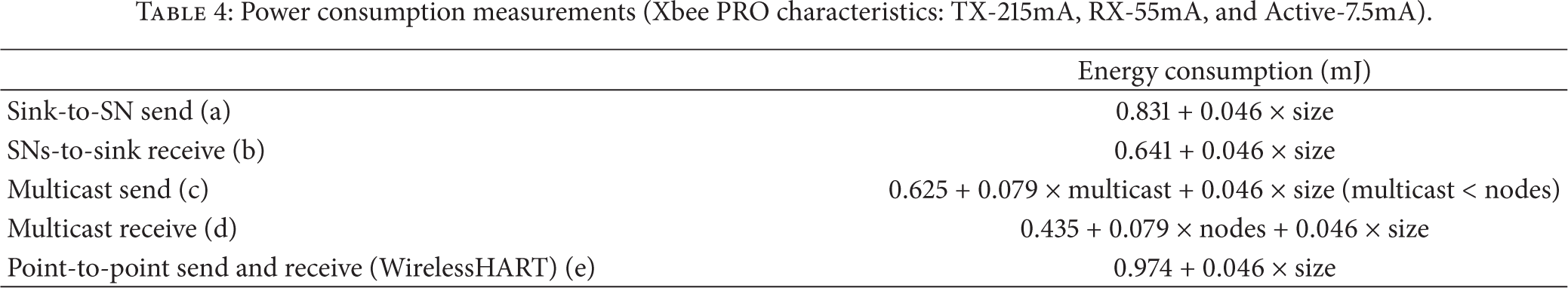
Table 4 shows the complete energy consumption of the Wireless HDLC communication protocol for a number of interesting points.
Sending sink-to-SN (a) and receiving SN-to-sink (b) traffic have the same incremental cost, but sink-to-SN traffic has a higher fixed cost associated with the PTP Sync message. This is exactly as expected. Sending sink-to-multiple SNs (c) and receiving multiple SNs-to-sink (d) traffic differ in their fixed costs and in incremental cost. Sending sink-to-multiple SNs traffic has a high fixed cost, also due to the cost of sending a PTP Sync messages. Sending multiple SNs-to-sink traffic has a high incremental cost due to the cost of sending each data with an HDLC header and flag. Sending and receiving multicast traffic (c, d) and sending and receiving point-to-point traffic (a, b) were expected to show the different incremental cost associated with the number of HDLC frames in superframe. Sending and receiving WirelessHART point-to-point traffic (e) and sending and receiving point-to-point traffic (a, b) have the same incremental cost but WirelessHART traffic has a higher fixed cost associated with the Data-Link packet (DLPDU) size [37].
Power consumption measurements (Xbee PRO characteristics: TX-215mA, RX-55mA, and Active-7.5mA).
Each DLPDU consists of the following fields:
1-byte set to 1-byte address specifier, 1-byte sequence number, 2-byte network ID, destination and source addresses either of which can be 2- or 8-bytes long, 1-byte DLPDU specifier, 4-byte keyed Message Integrity Code (MIC), and 2-byte ITU-T CRC16.
Compared to WirelessHART, which has one of the lowest energy consumption between the standard WSNs, the Wireless HDLC has a lower cost, associated with the header size of the data link layer, which is crucial in large-scale WSNs. Generally, because ZigBee and 6LoWPAN networks are not using TDMA-based MAC, they have higher energy consumption and so they are not suitable for large-scale linear WSNs [18].
Figure 12 shows the communication energy consumption for the network setup described in Section 4. This figure illustrates the energy consumption for two communication rounds in order to obtain data from all the 17 SNs. Moreover, it provides energy consumption for each query from sink and for the SNs responses. Sending sink-to-SNs commands has a high fixed cost due to the use of multicast commands for the different types of SNs. Receiving data from the first group of SNs and the alert sensors has a lower cost for the last SNs in the linear network which maximize the idle period in the TDMA slots. Receiving data from the second group of SNs and the alert sensors has a fixed cost for the first SNs and an incremental cost for the last SNs based on the total size of the superframe. The higher energy consumption for the SNs situated close to the sink is exactly as expected, because of the routing functionality of these nodes and the size of the superframe when it gets close to the sink.

Communication energy consumption for the WUNS setup described in Section 4.4.
From simulations based on MATLAB, the number of nodes that can be connected to a Wireless HDLC network with data rates depending on the TDMA technique for constant data bits is depicted in Figure 13. The maximum data bit rate of approximately 100 kbps is obtained with one node connected to the sink and is decreasing with the number of nodes in the linear network to approximately 2 kbps for 50 nodes and 0,89 kbps for 120 nodes. Hence, for a linear network with devices generating data as in the evaluation network (80 bits/measurement), the data bit rate of 0,89 kbps for 120 nodes allows the system to sample all the nodes in approximately 10 seconds. The maximum energy consumption per node and the energy consumption per data bit in relation to the number of nodes in the linear network are depicted in Figures 14 and 15. As illustrated in Figure 14, for maximum sampling rate of 20 ms and maximum data bit rate of 100 kbps, the maximum energy consumption per node is approximately 330 mJ when only one node is connected to the sink. Therefore, in this configuration, the node will stay most of the time in active mode (receiving and transmitting data from/to sink node). With the increase of the number of nodes connected to the network, the total energy consumption per node decreases because the nodes will spend more time in sleep. However, the energy consumption per data bit increases with the number of nodes as shown in Figure 15 because each node spends more time in routing activities.

Maximum rate for aggregator per nodes with constant node bit rate.

Maximum energy consumption per node for maximum sampling rate and maximum node bit rate.

Energy consumption for bits per packet transmitted.
5. Conclusion
In this paper, the HDLC standard protocol implemented for low-power linear WSNs was presented and evaluated. This protocol is evaluated in order to meet the objectives of interoperability, efficiency, and reliability in WSNs. First we introduced the large-scale infrastructure framework, focusing on the use of self-powered WSNs for protection and monitoring, the network architecture, and related works. Then we briefly presented the HDLC standard as a candidate protocol for linear wireless networks with bidirectional communication. We specified the advantages of this protocol in linear topology such as the possibility to transmit a variety of information, the use of poll/final procedure for control, or the use of unicast and multicast addresses with extending capability. We also proposed a novel way to create a half-duplex communication in a linear network based on low-power devices.
A hardware prototype for self-powered SNs, based on XBee PRO modules, has been developed for a large-scale infrastructure monitoring system. The preliminary results of a Wireless HDLC demonstration network with these sensors are very encouraging and also revealing. Using the HDLC protocol a user can interact at any time with different nodes in the network and can collect various types of data from many sensors at one time, which is an important capability for a linear network. Another advantage for low-power WSNs is that the HDLC does not increase the size of messages significantly and it does not introduce complex headers or fields to sensors data. Therefore, the Wireless HDLC is a low-power WSN which can be supplied entirely using harvesting approaches.
The investigation performed in this paper was an attempt to make open standard linear WSNs with an ultimate aim of achieving a standard low-power wide monitoring system, an essential requirement for the next generation of WSNs.
Footnotes
Conflict of Interests
The authors declare that there is no conflict of interests regarding the publication of this paper.
Acknowledgments
This work was carried out within the Sistemas Inalámbricos Para la Extensión de Observatorios Submarinos (SINEOS) Project under Grant CTM2010-15459 and the ENE2012-38970-C04-02 Analisis de Datos Basados en Aprendizaje automático y Sistemas Inteligentes de Adquisición de Datos Project under Grant CTM2009-08867 supported by the Spanish Science and Innovation Ministry (MINECO).