
Abstract
Five-hundred-meter aperture spherical radio telescope (FAST) is supported by a cable-net structure, which enables its surface to form a real-time paraboloid by active control. FAST project is currently in the construction and implementation stage. However, there are always a considerable amount of errors that existed in practice which may result in the deviation of the structure from its ideal model or design. Therefore, structural parameter sensitivity analysis was discussed, which is indispensable. However, such deformation operation would lead to about 500 MPa of fatigue stress variation amplitude in the cable-net structure. Optimized deformation strategy is proposed to release the fatigue stress of the cable-net structure, which would be of advantage to improve the reliability of the cable-net structure. In the paper, the variation ranges of structural parameters were rationally determined. Based on local sensitivity analysis and global sensitivity analysis method, finite element model was used to study the effect of different structural parameters on the static behavior. It can be concluded that the effect of several key design parameters such as the cutting length and the elastic modulus of cable on the cable force is significant. The global sensitivity analysis indicates that the cable force range of the cable-net is −19% to 27%.
1. Introduction
FAST (five-hundred-meter aperture spherical radio telescope) is a major scientific project belonging to the national “11th five-year plan.” Upon completion, it will become the world's largest telescope, bigger than the 305-meter Arecibo telescope of the United States [1–4].
The cable-net of the active reflector of FAST is a complex structure system composed of about 6670 main cables segments, 2225 down-tie cables, 50 latticed pillars, and steel ring beam of diameter 500 m, as shown in Figure 1. The 500 m aperture spherical main cable-net is weaven using geodesic method. The reflector panels will be installed at the nodes of the cable-net. All the nodes of the cable-net will be located on the spherical cap of radius 300 m centered at point O. Each of the cable-net nodes is pulled by its down-tie cable driven by an actuator to control the deformation of the cable-net to form different paraboloids of 300 m aperture [3–5].

Chart of the cable-net structure of the active reflector of FAST.
In observation process, searching and tracking the interested astronomical objects are structurally realized by the elastic deformation of the cable segments, which means that the cable segments will endure long time and reciprocating fatigue loads. Analytical results show that the amplitude of the stress variation of the main cable segments will reach or exceed 500 MPa, which is more than twice of the current related standards of the cable structures [6–8]. The deformation optimization strategy is of great importance to the decrease of the stress variation amplitude of the cable-net in the observation process, to the safety and reliability of the structure.
FAST reflector cable-net is a complex large span space structure which is demanded a surface precision of fitting RMS better than 5 mm [1]. In reality, the cable-net is a high-order hyperstatic structure with uncertainty in material properties, machining tolerance, boundary conditions, and loads. Usually the true value is not easy to be obtained, and a variety of sources of errors are inevitable in the construction of the telescope, including the cutting length of cable preparation, the elastic modulus of the cable, and the position of the anchor nodes of the down-tie cables. Errors of different parameters bring different results for the structure safety and operation performance. It is necessary to control the error budgets by sensitivity analysis.
With a background of the construction process, later observation, and maintenance process, the paper firstly discussed the influence of the deformation strategies to the stress variation amplitude of the cable segments, with an aim of reducing the stress variation amplitude of the cable-net deformation, and with a methodology of numerical simulation of the cable-net deformation process by large-scale FEA (finite element analysis) software ANSYS. Sensitivity analysis is then implemented combining single parameter and multiparameter method. By extracting the ratio of the actual cable stress to the standard cable stress as a reference to evaluate the cable stress variation, the results are used to evaluate the influence of a variety of errors to the cable-net structure and to provide a reference to the control of the construction process and the design of the actuators.
2. The Optimization of the Deformation Process
The deformation of the cable-net is one of the main loads of the FAST cable-net. The response induced by the deformation load is determined by the deformation strategies (the geometrical relationship between the paraboloid and the spherical reference surface) of the working paraboloid. For different deformation strategies of the working paraboloid, the internal force of the cable-net structure varies correspondingly [9]. Actually, the deformation strategy is a function of the illuminated paraboloid, as is the geometrical relationship between the paraboloid and the reference sphere. Due to its symmetry, one dimension is sufficient for the fitting of the function. It can be found from the fitting of the paraboloid and the sphere that the difference between the sphere and the paraboloid will be small if appropriate focus ratio F is chosen [2]. If the center of the sphere is chosen as origin of coordinates and the observation direction is set as y-axis, the paraboloid and the reference sphere cap can be described by the equations below:
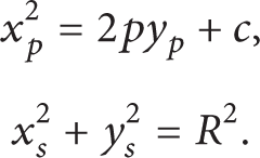
For the determined cable-net design, the cable-net aperture is 500 m, the sphere radius R of the cable-net is 300 m, the illuminated aperture a is 300 m, and p is distance of focuses to directrix in the paraboloid. To maximally extend the observable angle, it is necessary that the illuminated paraboloid be deformed to the outer brim of the reflector surface. Since the ring beam around the cable-net is fixed, it is required that the border of the illuminated aperture is coincident to the border of the reference sphere cap. That is, (2) c should be satisfied:

For the cable-net deformation process, the actuators are used to drive the nodes to form different paraboloids, being pulled by the actuators for the cable-net nodes at the outer side of the reference sphere cap and being released by the actuators for the nodes at the inner side (Figure 4). For this reason, the stress distribution of the cable-net is closely related to the paraboloid [10, 11]. The stroke of the actuators is a key indication in the cable-net deformation process, which is determined by the distance between the sphere cap and the objective paraboloid. If the center of the sphere is chosen as origin of coordinates and the observation direction is set as the polar axis [8], the cable-net within the illuminated paraboloid can be described in polar coordinates as (3), where ρ is the polar axis with unit in meters:

In (3), θ is the polar angle with unit in degrees. The distance h between the paraboloid and the reference sphere cap is found to be

2.1. The Principle of the Deformation Strategies
Based on the requirements of the principle of different deformation strategies and aiming at the function requirements of the FAST telescope, the value range of the focus ratio F of the paraboloid is obtained. The corresponding stress variation amplitudes are obtained by numerical simulation using ANSYS. The relations between the stress amplitudes and the focus ratio F are established to search for deformation strategies of optimized stress variation amplitudes, with the following principles considered:
least actuator stroke;
least peak distance between the paraboloid and the reference sphere cap;
the length of the parabolic curve and the arc is equal to the illuminated paraboloid.
For the first two deformation strategies, extreme method can be used to find the solution. For the case of (1), the least actuator stroke is the optimization objective, which is named strategy I. The solution is that the focus ratio F is 0.4665, the focal length p is 279.9038 m, and the parabolic coefficient c is 167940. For the case of (2), least peak distance between the paraboloid and the reference sphere cap is the optimization objective, which is named strategy II. The result focus ratio F is 0.4611.
For the last deformation strategy III, numerical method is used to find the solution. The length of the parabolic curve can be expressed as
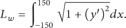
Substituting the first line of (1) into (5), we have

The arc length can be expressed as L r = R·θ = 100π, where θ = π/3 is the central angle of the illuminated area, in radians. The third principle requires that L w = L r .
Using Newton iteration method in MATLAB, the error can be controlled within 1 mm after about 10 iterations and the result is that the focal length p = 276.1557 m and the focus ratio F is 0.4603. The parameters corresponding to the deformation strategies above in summed into Table 1.
Related parameters of three types of working paraboloid.

2.2. Optimization Analysis
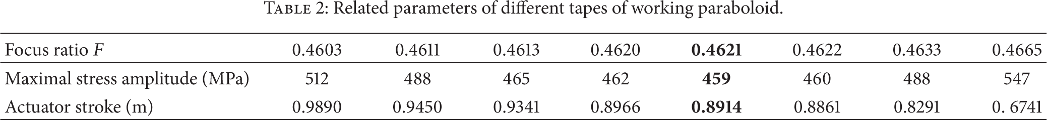
The parameters of different deformation strategies are input into ANSYS to obtain the corresponding maximal stress variation amplitude, as shown in Figure 3. Using the maximal stress variation amplitude as analytical factor, tracing the variation tendency of stress amplitude with the focus ratio, the stress amplitude is assumed to be affected by the focus ratio F of the paraboloid. Fitting result of the data shows that when focus ratio F is 0.4621, the stress variation amplitude has smaller value. Numerical simulation for the deformation strategy of F = 0.4621 gives stress variation amplitude of 459 MPa. To verify the correctness, F = 0.4620 and F = 0.4622 are applied for numerical analysis. The result is shown in Table 2. It can be proved that when focus ratio F is near 0.4621, the stress amplitude has least value and the actuator stroke is 0.8914 m which satisfies the design requirements.
Related parameters of different tapes of working paraboloid.
3. Sensitivity Analysis of the Structural Parameter Errors
The parameter sensitivity analysis is usually classified into single parameter method and multiparameter method [7]. For single parameter method, only a single parameter is examined to evaluate its influence to the model results, with the other parameters being kept constant at their central values. For multiparameter method, multiparameters are examined and analyzed, including each parameter and the interaction among these parameters.
According to the requirements that the FAST paraboloid should not exceed the brim of the aperture 500 m and the maximal observation zenith angle of 26.4°, 550 nodes are selected as the central point of the paraboloids. Based on the ANSYS software, a form finding analysis program was coded for the active paraboloid deformation. The working area was set to be paraboloid by adjusting the nonstress length of the down-tie cables in the working area. For each analysis procedure, the stress distribution of the cable-net was calculated independently assuming that the center of the paraboloid deforms actively to each node specified as central point of a paraboloid. For each node, there will be a calculation case, and the cable stress corresponding to each cable segment for the 550 cases are stored.
FAST cable-net is formed using geodesic method. The cable-net is of 1/5 symmetry about the vertical line through the center of the sphere cap [8, 12]. Since each of the five symmetrical sectors is antisymmetric about its medial axis, the cable-net is of 1/10 symmetry. The main cable at symmetrical positions can be classified into a same group of same specifications. Considering the 1/10 symmetry of the cable-net, the calculation load can be effectively reduced. For the calculation case, the center points of the paraboloid are shown in Figure 2 (Red nodes). To include the effect of the temperature load, temperature rise of 25°C, normal temperature of 0°C, and temperature drop of 25°C are used for the working condition of reference sphere cap and 65 paraboloids. There are 198 working conditions in sum.
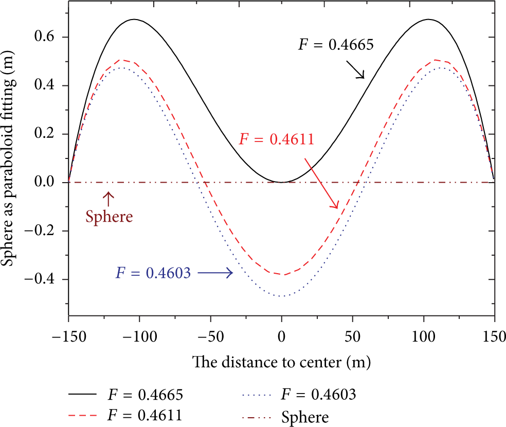
Distance between reference sphere and different paraboloid.

Stress amplitudes of different focus ratio F and deformation strategies.

Positions of the central points for typical paraboloids of 1/10 symmetry.
An analytical model of FAST cable-net is constructed the paper using FEA software ANSYS. LINK10 elements are used to simulate the mechanical response of the cable segments. The entire model includes 6670 main cable segments and 2225 down-tie cable segments. For each error analysis, in consideration of the factor that the down-tie cables can be controlled by the actuator both in the construction and operation stage, only errors of the parameters of the main cables are considered in the modification of the FEA model, with the related parameters of the down-tie cables kept unchanged. After the modification of the model parameters, the working conditions of each paraboloid are calculated. The cable force of the standard model is to be used as reference in the data processing procedure. The ratio of the corresponding cable force after each consideration of errors is used as the basis of cable force variation level.
By analyzing the characteristic of the cable-net structure of FAST and the problems probably met in the construction and operation stage, 6 variables are selected to perform error sensitivity analysis: the elastic modulus of the cable body, the cutting length of cable preparation, the weight of the panels and nodes, the position of the outer nodes of the cable-net, the position of the anchor nodes of the down-tie cables, and the friction coefficients of the sliding support.
3.1. The Cutting Length of Cable Preparation
The cables are each made independently. The length error of a single cable has no significant effect on the characteristics of probability and statistics of the length of all the cables. Based on the central limit theorem [13], it can be reasonably assumed that the error of the cutting length of cable preparation follows normal distribution approximately. Considering the technological level of the cutting length of cable preparation of the cable factory, the maximal error of the cutting length of cable preparation is assumed to be 1 mm. In the numerical simulation, the cutting length of the main cables should averagely satisfy the normal distribution in the range of (L − 1,L + 1) mm, with base length of L mm, standard deviation of 1/3 mm, and confidence probability of 99.73%.
3.2. Elastic Modulus of the Cable Body
In the error calculation of elastic modulus, the normal distribution in the range of (180, 200) GPa, with average value of 190 GPa, standard deviation of 10/3 GPa, confidence probability of 99.73% is under discussion. As shown in Figure 5(b), the error of the elastic modulus of the cable is of significant influence to the cable force. In the standard model, the elastic modulus of the cable is assumed to be 200 GPa, which has approximately covered all the adverse effects of the elastic modulus of the cable to the load capacity of the cable.
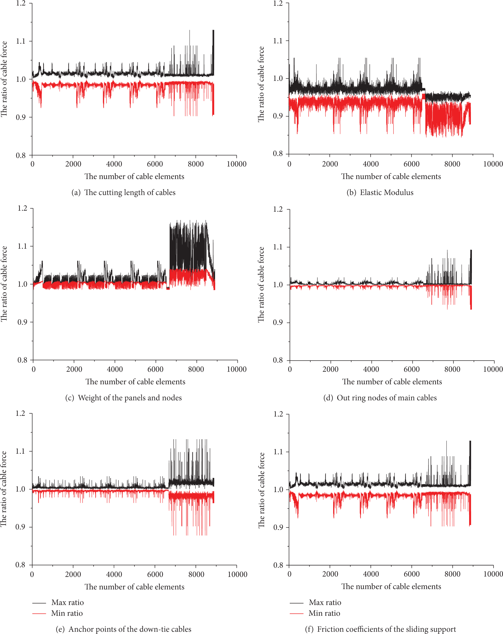
Cable force versus error of different parameters.
3.3. The Weight of the Panels and the Nodes
The constant loads to the FAST reflector cable-net structure consist mainly of the following: (1) the panel elements, (2) the cable weight and (3) the cable-net nodes and the cable head anchors. Since the specification of the cable body and its density have been determined and the weight of the cable can be ignored, the errors induced by the weight uncertainty of the reflector panel elements, main cable nodes, and the cable head anchors are discussed in the paper. The error of the weight can be assumed that the weight of the back frames, the nodes, and the cable head anchors is reduced by 10%. As shown in Figure 5(c), the cable force variation induced by the reduction of the weight of the panels and the nodes is in the range of −2%~17% and has significant effect on the down-tie cables.
3.4. The Position of the Outer Ring Nodes of Main Cables
The entire cable-net is connected to the ring beam by the 150 outer ring cables. It is assumed that the position of the outer ring nodes deviates 10 mm along any direction. As shown in Figure 5(d), the position error of the outer ring nodes of the main cables has significant influence on the outer ring down-tie cables, with cable force variation to the range −7%~9%. For the other cable nodes, the influence of the position error of the cable nodes is not significant.
3.5. Anchor Position of the Down-Tie Cables
In principle, the anchor position of the down-tie cables should be at the extended line from center of the reflector sphere cap to the nodes of the main cables [10, 11]. In construction, the position of the down-tie cable nodes should be controlled in angle. For the sensitivity analysis in the paper, it is assumed that the positions of the anchor deviate 1.5 degrees at any direction. As shown in Figure 5(e), the position error of the anchor will result in a variation of the cable force of the down-tie cables to the range of −12%~13%.
3.6. Friction Coefficients of the Sliding Support
Each of the 50 latticed pillars is of different height, which will lead to great difference in horizontal stiffness. The unevenness of the stiffness will have great effect to the entire structure including the cable-net. The ring beam is a uniform ring of width 11 m, which has stiffness large enough to be used to support the cable-net. For the two reasons above, the ring beam segments are connected to the latticed pillars mainly by the ring beam support. The ring beam support can be set to different boundary constrained conditions. The boundary conditions in the current model analysis are set to be circumferential constrained and radial free for the steel ring beam. In the standard model, the friction coefficients of the sliding support are set to be 0.03, and set to be 0.05 when performing error analysis. As shown in Figure 5(f), larger friction coefficients of the sliding support will have adverse effect on the outer ring cables of the cable-net, with cable force variation to the range of −10%~13%.
3.7. Sensitivity Analysis for Multiparameter Errors
Now suppose that the effect on the model analysis results for the case that the six structural parameters mentioned above vary simultaneously and interact with each other. Since the cable-net is connected to the ring beam by the outer 150 cables, the outer 150 cables and the inner cables will be studied separately in the analysis. As to the cable force of the standard model, the cable force of the inner cables varies in the range of −19%~27%, and the cable force of the outer cables varies in the range of −5%~4%. It can be seen that the variation amplitude of the inner cables is relatively large. The force variation of the down-tie cables of the inner cables is in the range of −7%~19% and −12%~6% for the outer cables, as shown in Table 3.
Results of sensitivity analysis for multiparameter errors.

4. Conclusion
(1) The deformation strategy for the paraboloids of focus ratio F = 0.4621 was established, for which the stress variation amplitude was reduced by 89 MPa compared to deformation strategy I, and the actuator stroke was reduced by 0.536 m as compared to deformation strategy II. The number of cable segments of high stress amplitude is fewer than strategies I and II. The deformation strategy is a reference to the later observation model input of FAST. The cable segments with high stress variation amplitude are distributed mainly in the central part and the 1/5 symmetry axes of the cable-net. The cable segments which tend to meet fatigue problem can be counted, which will be a reference to cable force sensor arrangement.
(2) The cutting length of the cable preparation is a main factor which affects the cable force. The error of the position of the outer ring nodes and the friction coefficient of the sliding support will affect mainly the cable force of the outer ring. Based on the single parameter error analysis result, the error control standard of the cutting length of the cable preparation, the weight of the panel, and the weight of the nodes are roughly determined.
(3) The error sensitivity analysis of the multiparameter shows that the cable force of the cable-net varies in the range of −19%~27%. Considering the sensitivity, the force of the down-tie cables is analyzed to provide the load for the actuator design. Furthermore, when choosing the cable specification and getting the reaction force of the anchor of the down-tie cables, the cable force variation amplitude induced by these errors should be considered to ensure the safety and rationality of the design.
Conflict of Interests
The authors declare that there is no conflict of interests regarding the publication of this paper.
Footnotes
Acknowledgments
This work was supported by the National Natural Science Foundation of China (Grant no. 11173035). The authors would like to thank all their colleagues for their contributions to the study of cable-net structure for FAST.