
Abstract
Developing, deploying, or reprogramming an application in a short time and at a low cost is necessary in wireless vehicular sensor and vehicular ad hoc networks. However, the existing technologies, which usually take a long time or require a high cost, cannot support a system and common solution. In this paper, we propose an application-customized common platform for wireless vehicular sensor networks. The common platform can provide us with a friendly web-based user interface, so as to make deploying or reprogramming a running field application in VeSANs become very convenient, simple, and efficient. According to the requirements of the common platform and the presented architecture model, we have implemented the common platform in both hardware and software. The in-field experiment and the test results show that the platform is available for the developing and deploying of WSNs for different applications.
1. Introduction
With the recent advances of wireless communication and embedded systems, a potential and huge market for wireless vehicular sensor and vehicular ad hoc networks (VeSANs) has quietly appeared. To acquire more valuable sensing data through VeSANs, an amount of wireless sensor devices should be deployed in the vehicles. However, in the traditional concept, different field applications usually need to deploy different vehicular sensor devices equipped with the corresponding sensors, which will result in the complex system and unnecessary resource waste. Besides, for any field application, a long development process is needed from appearing to maturation. During the long period, the software changing of field applications deployed in the vehicular sensor devices and system update may also take place for several times. A common platform that can support system updates and field applications customization will greatly help to shorten the time of the development and save a lot of costs. But due to the limitations of bandwidth, energy, memory, and processing resource, the design of the common platform is filled with challenges, especially the remote reprogramming of wireless sensor networks in the complicated multihop network environment.
In order to address the above issue, the researchers have developed many different methods to design reprogrammable sensor nodes for different system requirements and system update. Hui and Culler present Deluge, a full system image replacement method, to support network programming [1]. Dunkels et al. use the standard ELF object file to finish the run-time dynamic linking for reprogramming [2]. Dong et al. present a mechanism called Elon for enabling efficient and long-term reprogramming in wireless sensor networks [3]. Besides, approaches based binary differences [4–6], script language [7, 8], virtual machines [9–13], network parameters reconfiguration [14–16], open framework support [17, 18], and the loadable native code in Contiki [19] and SOS [20] also have their own features to support reprogramming.
However, the above published studies mainly focus on the single node reprogramming, and even the interface and method for remote operations over the air in the wireless sensor network are not referred to. A complete common system platform which could be used in the complicated network environment just like VeSANs and could provide the developers and the consumers with an open model, APIs, and a user-friendly graphics interface is required.
In this paper, we propose an application-customized common platform as shown in Figure 1, which can be used in VeSANs. The proposed application-customized common platform does not add any new hardware device to VeSANs. In the platform, the management server holds all the working states of the network and through the web-based interface provided to the user, we can watch the running information of each node of the network and its sensing data in time. More importantly, we can manage, control, and change the parameters of the field applications running in the nodes and even update the nodes with an entirely new field application according to our needs through the web management server. Therefore, it becomes quite easy for us to develop, deploy, and evaluate a new application used in VeSANs through the platform.

The sketch of application-customized common platform for VeSANs.
Now, we have implemented the whole common platform using a PC as the management server, a notebook with a USB radio model as the gateway, and several KAREN (KAREN: a sensor development board that used the TI MSP430 CPU for version 1, the NXP LPC 1769 CPU for version 2, Atmel Radio RF231/RF212, and some other peripheral interfaces) boards as the ordinary sensor nodes. Based on the platform, we have developed the basic applications such as temperature/humidity and light intensity data collection and successfully finished reprogramming the wireless sensor nodes. Besides, we also made an industrial application used to frequently and periodically collect the status parameters of the weld machines and send the control commands to them. Because of the commonality of the platform and the modular design of both the hardware and the software owned by the KAREN boards, it is feasible to deploy and measure the customized applications on the platform conveniently.
To evaluate the function and the performance of the platform, we take a basic temperature data collection application, for example, measuring the communication delay time, and for remote reprograming over the air, we change the applications running in the selected nodes to another industrial CAN [21] data collection application widely used in the automobile electronic field. The measure results verify the availability of the common platform.
The rest of the paper is organized as follows. In Section 2, we discuss the design requirements of the application-customized common platform. Section 3 presents the scheme details of the application-customized common platform. In Section 4, we describe our implementation on both the hardware and the software. Our experiments and test results are presented in Section 5. Finally, we conclude the paper and give out our future work in Section 6.
2. Design Requirements
The aim of the common platform is to set up a public service platform for the application development and deployment in VeSANs, which can save the cost of hardware devices for more developers and accelerate the application development process. For researchers, it can help to evaluate the real performance of their minds rather than ideal numeric analysis or simple simulations.
To achieve the above purpose, some requirements need to be taken into account. In this section, we will enumerate these requirements.
2.1. Friendly User Interactive Interface
Due to the different users of professional knowledge, the user interactive interface of the common platform must be designed friendly, so that it can visually guide the users, not only those owning widely professional technologies but also the ones interested in the special field application development, even ones who only want to evaluate some kind of algorithm designed for the network, to operate the platform.
Another important factor of the design of the user interactive interface is the convenience to access the common platform. After accessing the common platform, the users should be able to deploy their applications or make their experiments easily. In order to provide more users of different geographical locations to access the common platform, the user interface design must be networked. Nevertheless, there is only a set of physical hardware infrastructure devices in the common platform, and it will not bring more advantages than other existing schemes.
2.2. Standard Sensor Interface
The field sensor is the source of the sensing data and considered as one of the indispensable components in VeSANs. But a kind of field sensor usually is used to collect sensing data by one special field application other than all field ones. Since the common platform is designed to satisfy the requirements of as many field applications as possible, it should have the ability to be equipped with different kinds of field sensors. Therefore, it means that the sensors that can be installed in the sensor node of the common platform should be diverse.
However, the existing sensors used in the industrial field are usually designed according to different standard specification, and their communication interfaces include A/D, UART, I2C, SPI, and USB. Therefore, the sensor node in the common platform should support all these standard interfaces.
2.3. Changeable Hardware Module
Modular hardware design is necessary for the sensor node in the common platform. A node in the platform cannot be equipped with all kinds of sensors or radio modes simultaneously. Modular hardware design makes it possible to change the sensor module or the radio module, so that various sensing data can be collected and different radio modes can be developed and evaluated just by changing the corresponding modules in the common platform.
Besides, modular hardware design can minimize the cost of development and evaluation. For a customized application or a special experiment on the platform, it is enough for the users to finish their plans by only developing or changing the relevant module in the hardware. Of course, the necessary software running in the sensor node should be developed and reprogrammed.
2.4. Application Reconfiguration and Profile Saved
For an installed application in the common platform, the running parameters may need to be changed due to the optimization or the changed application scenarios. Even more, the whole configuration profile needs to be modified and saved during the runtime due to the different environment or power reset.
Certainly, the application reconfiguration or profile saved can be operated by remote programing. However, in order to better save the communication overhead and the time of the development and the deployment, support to application reconfiguration and profile saved is highly significant for the common platform.
2.5. Remote Reprogramming Support
During the development of a field application using the common platform, some software bugs may need to be fixed or a newer version of the software needs to be updated. Under these situations, the entire code residing in the field sensor node may need to be replaced. When deploying a new field application in the existing sensor node, the original code should also be changed. Because of the unpredictability of the software update and a new application deployment, we cannot program all these codes to the sensor node at the beginning.
On the other hand, the limited memory of the sensor node in the common platform usually cannot host more than one version of the application software, not to mention the software corresponding to more applications. Hence, remote reprogramming becomes the only way to make the common platform to be more scalable.
3. Application-Customized Common Platform
The proposed application-customized common platform consists of sensor nodes, access gateway, and management server as shown in Figure 1. In the following, we will introduce the system model, the design details in each device, the basic working protocol, and operation mechanism.
3.1. Network Architecture Model
The network architecture model of the platform adopts the web-based service technologies. It consists of user interface layer, management interface layer, application layer, service abstract layer, network stack layer, hardware abstract layer, and physical infrastructure layer, as illustrated in Figure 2. The functions of each layer are as follows.
User interface layer. It is directly user-oriented. Through the interface, we can access the common platform, deploy the desired customized application which has been developed, monitor the running state of the network, and obtain the sensing data. Management interface layer. It is a cross layer that can contact all the other layers. Through it we can manage the running parameters of the customized application, control the network protocols, and even change the entire running program installed in the platform. Application layer. It is the most business application of the platform; it can finish data collection, data storage, data mining, and data presentation. Service abstract layer. Some abstract standard service interface functions are defined in this layer, such as the service creation and release, the service event process, the timer operation, and the message sending and receiving interfaces. Through the abstract standard service interfaces, we can easily develop and deploy the desired field application. Network stack layer. This layer defines the basic network communication functions, including message RX/TX, pack/unpack, queue, and network protocols. Hardware abstract layer. This layer is used to shield the differences of the underlying hardware components, providing the standard operation interfaces to the upper layers. Physical infrastructure layer. This layer consists of all the physical hardware resources including the field sensors, radio modules, and computing and storage resources.

Network architecture model of application-customized common platform.
3.2. Sensor Node
Besides the modular design and the above architecture, the sensor node of the platform is designed to support the field application customization through reconfiguration, profile, and remote reprogramming. In order to achieve this purpose, the flash memory of the sensor node is parted as several different areas as shown in Figure 3. The boot loader area is used to store the loader program. The default program area stores the code of the deployed customized application. The initialization parameters of the application when it is turned on are generated according to the configuration saved in the profile area. The reprogramming receiving area is used to temporarily store the reprograming data. At the end of a reprogramming process, the area will be wiped. The recovery area is designed to deal with the wrong reprogramming operation and make sure the node can reboot with the default original program.
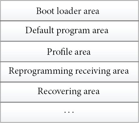
Usage of the memory in the sensor node.
When the sensor node is powered up, it starts the program flow as shown in Figure 4. First, the boot loader checks the update flag. If it is true, the reprogramming flow is activated; otherwise, the default program will be loaded. The code check process makes sure that the received reprogramming code is correct and complete. In normal, the sensor node runs in the default program. Once it receives the update command, it will receive and store the reprogramming code and set the update flag. If it receives no reboot command, it will still run back to the primary default program. This design of reboot command for reprogramming makes it possible to upgrade multiple sensor nodes simultaneously at the specified time. When the sensor node receives the reboot command and pass the reprogramming code check, it can replace its origin default program and run the specified one.
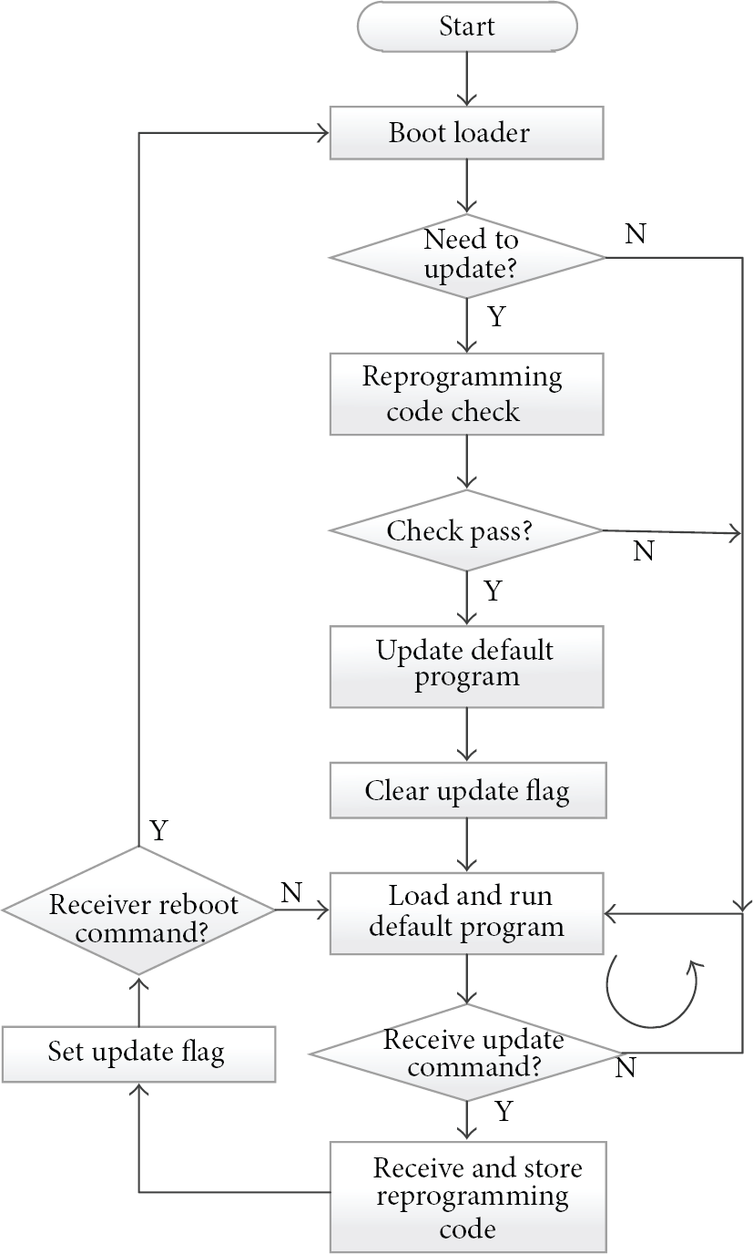
Program flow of the sensor node.
3.3. Access Gateway
In the common platform, the access gateway is responsible for translating the messages represented by different network protocols between the local network and the global network. In the local network, the gateway needs to work with the same protocol as the sensor nodes, such as Wi-Fi and ZigBee. In the global network, it will be connected to the Internet with Ethernet and IP.
The compositions of the access gateway are mainly four modules: RX/TX module, protocol translating module, mapping table module, and message queue module.
The mapping table module is introduced to maintain the relationship between the two different address spaces on either side of the access gateway, so as to route the packet down to the right node in the sensor network or up to the corresponding management server. The message queue is used to buffer the received packet and the ones to be sent. Meanwhile, the message queue plays a role of traffic shaping to avoid too many packets to congest the node or the link of the wireless sensor network in a short time interval.
3.4. Management Server
The management server is the most important component of the platform. It can be considered as the brain of the platform. Nearly all the operations should pass to the management server. The management server of the common platform is mainly composed of four software modules, including communication module, computation module, web service module, and database module.
The communication module is used to receive and send packages from and to the sensor nodes. The computation module is used to compute the route of the wireless sensor network, schedule the wireless channels, and process the users’ commands. The database module is used to record the running states of the network and the list of all available resources. The web service module is responsible for providing the web interface to the users.
3.5. Basic Working Protocol and Operation Mechanism
Before using the platform, we should register the available hardware devices and the authorized users in the database first, because only the registered devices can join the deployed wireless sensor network. Similarly, only the authorized users registered in the database can access and operate the system with the web service. Now, we assume that a field application has been deployed in the platform. If a user wants to watch the sensing data or the state of some node or the network, the sequence diagram as shown in Figure 5 gives out the operations.

Sequence diagram of sensing data collection and network monitor.
When the user logs in into the web system of the management server successfully, the registered sensor nodes can be seen on the window of the web browser. But the state color of the sensor node may be gray which indicates the node has not yet joined the network. If we powered on the sensor node, it will scan its neighbors on the public channel for joining the network first. When the node selects a neighbor as its proxy, then it will initialize and finish a joining process with the help of its proxy. Once the management server notices the joined node, it will change the state of the node from absence to normal, and the node state color will be marked yellow. Meanwhile, the management server will compute the available network resources, such as the route and the radio channels, and send the decisions to the joined node. After that, the sensor node can use the assigned network resources to send the sensing data to the management server. At this time, the user can select the sensor node and expand the detail window to see the sensing data collected by the senor node.
In the platform, the sensor node can be configured to collect sensing data periodically or triggered by the specified events. In order to organize a multihop network, the sensor node should be configured with the forwarding and aggregation functions because a sensor node may have several child nodes. The data aggregation mode improves the efficiency of the data forwarding but introduces a little delay time. After all, the child nodes of one node cannot send the sensing data at the same time. When the management server receives the sensing data message, it can push the new state of the sensor node or the entire network to the user's web browser in time.
Although the management server can dig some useful information from the collected sensing data by the joined sensor nodes, it is not enough to learn about the detail network status. In order to gain the complete status information of the network, all the joined sensor nodes will report their existence and their views to neighbors to the management periodically.
The above operations can deal with the sensing data collection and the network monitor, but the remote programming should be using the following operation steps as shown in Figure 6.

Sequence diagram of deploying a new application.
In order to deploy a new customized application, the user should first finish the program development of the new application; then through the web interface, he/she can upload the new program to the management server. The server will generate the reprograming code according to the algorithms which have been set. After that, the user can select the sensor nodes that need to be upgraded and send out the reprogramming command and code. The server and the gateway will forward the reprogramming command and code to the selected nodes. When the selected sensor nodes receive the reprograming command, they will change their upgrade state, store the followed reprogramming code, and wait for the reboot command. When the user obtains the information that the distribution of the reprogramming code is finished, he/she can send out the reboot command to the selected nodes to load the new application in the platform.
4. Implementation
According to the above scheme, we have implemented a demo of the application-customized common platform and deployed a simple application of temperature sensing data collection, and we also successfully reprogrammed the application to be changed to another industrial application of CAN data sample. In this section, we will introduce our implementation in the aspects of both the hardware and the software.
4.1. Hardware Implementation
In order to save the costs, now the main boards of the sensor node, the radio module, and the sensor module are designed into a PCB board. However, with the same design, we change the radio chip from AT86RF231 to AT86RF212 and in the newer version the CPU is replaced by NXP LPC 1769 from TI MSP430F2618 because of the lack of the RAM memory; the result shows that it works fine. Figure 7 shows us the physical picture of the KAREN sensor node. In Figure 7, the main blocks, including CPU MSP430F2618, radio AT86RF231, power, CAN, and temperature sensor, have been labeled.

The board of KAREN node.
Besides the sensor node, we also set up a complete demo experiment prototype of the common platform as shown in Figure 8. In the prototype, there are more than one hundred sensor nodes, an access gateway acted by a notebook with a USB radio module, and a management server installed by a PC. Unfortunately, the access gateway and the management server are not contained in Figure 8.
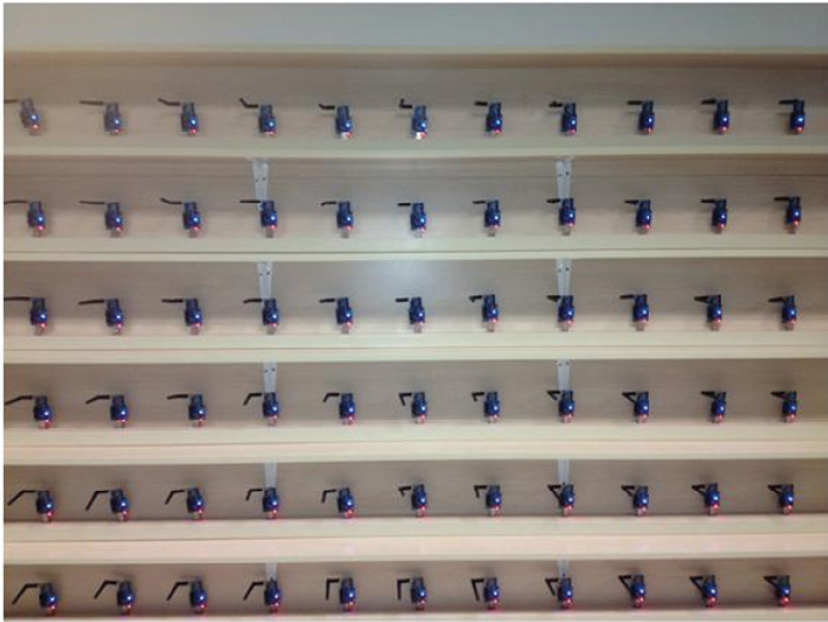
The experiment prototype of the common platform.
4.2. Software Implementation
In the software implementation of the sensor node, we abstract the hardware modules into the standard drivers for the upper layer calls, and this approach simplifies the complexity of the development when a new hardware module is added or changed. In the network stack, we implement CSMA and TDMA link protocols, based on the IEEE802.15.4 specification, and a custom network protocol. Based on the network stack, we realize a multihop network organization scheme and develop a temperature collection application and a reprogramming protocol on our prototype.
In the management server, we adopt Tomcat and MySQL to set up the web service environment and use the more recent popular software Flex Builder to develop the web-based management platform for the sensor networks. Figure 9 is the monitor interface of the sensor nodes, and Figure 10 shows the interface of deploying a new program with the common platform.

Monitor interface of the sensor nodes.
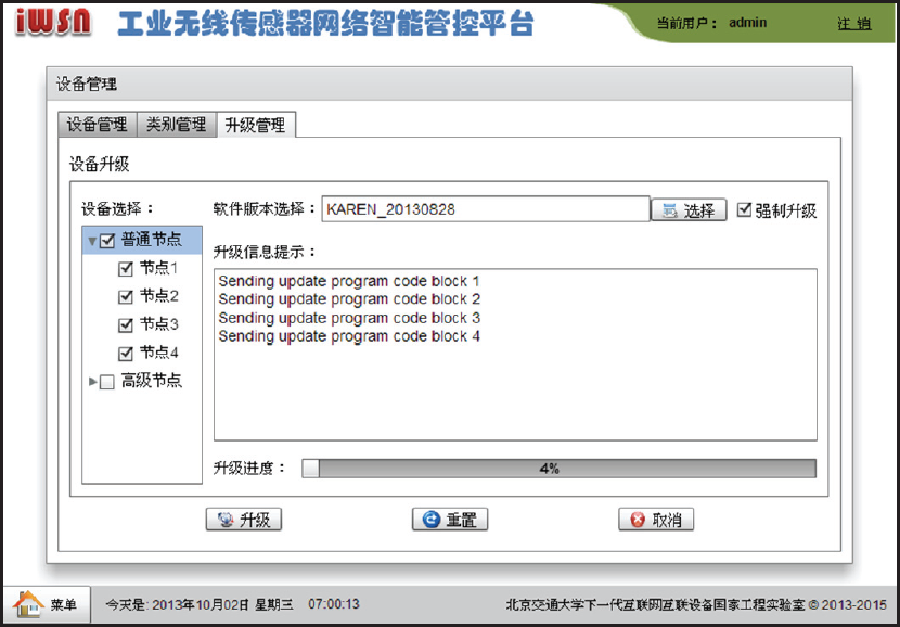
Deploying a new program with the common platform.
From the management platform, we can monitor the state of the sensor node, for example, online, working, fault, and so on. Besides, we can see the collected sensing data through double clicking the selected sensor node. The upgrade interface supports multiple sensor nodes to be upgraded simultaneously. Of course, there are other functions owned by our realized management platform. In this paper, we will not give out the further explanation.
5. Experiment
Based on the prototype of the application-customized common platform, we make the following experiments. It is necessary to note that all of the experiments are made using the free ISM 2.4 GHz/780 MHz frequency band and the TDMA link protocol, the slot time is set to 10 ms, and the super frame time is 500 ms. The slots are divided into two categories; one is dedicated slots used by the specified pair of nodes to send or receive the sensing data and the control commands, and the other is public slots which can be used by all the nodes to broadcast, monitor, or compete for joining the network. In order to have sufficient slots available, we adopt 4 radio modules working in four different channels in the access gateway.
5.1. Sensor Nodes Join the Network
In this experiment, we select 80 sensor nodes to join the network. Because of the limited memory, we limit the maximum number of neighbors to 10 and the maximum packet queue length to 10. Figure 11 gives out the time cost when all nodes joined the network from the moment they are powered up at the same time. If the management server receives a node's join request and the server responds to the requesting node and if the server receives the acknowledgement for the corresponding response from the joining sensor node again, we consider the node has joined the network successfully.

The time cost of all sensor nodes that joined the network.
From Figure 11, we can see that the entire cost ranges between near 100 and 200 seconds. From the first look, the test values are greater than the ones we expected, because the basic join process only contains three interactive messages, even though the sensor node joined the network through three hops, and the whole process can be finished in about 10 super frames which only last 10 seconds in the assumption of no failed competition and no packet loss. But in fact, the test values include the duration to scan neighbors, synchronize with the parent node until the clock synchronization reaches a steady state, and schedule the channel and time slot resources. In the design of the software, the preparation for the join is set up to 26 seconds. And one sensor node usually needs to restart the preparation process when its parent finishes the join successfully. In the real test environment, the failure of the time slot resources also increases the time cost of all the nodes that joined the network.
However, this average test value should be accepted by many sensor network environments.
5.2. Temperature Data Collection
On the basis of Experiment 5.1, we obtained the response time of the web interface when the user actively sends the requests for the temperature data. Figure 12 gives out the test results. From Figure 12, we can learn that the average time during an interaction through the user interface with the platform usually remains between 1 second and 4.5 seconds, and the time cost increases with the hops. The test results are basically consistent with the design of the scheme. After the optimization of the time slot schedule to make the working slots orderly organized according to the number of hops to the access gateway, almost all the interaction can be finished in 3 seconds. Of course, there is much to do to make further optimization to the value of the test time.

Average time during an interaction through the user interface.
Besides the time cost records, we have also counted the number of received periodic temperature sensing data in each experiment—the period is set to 1 second and the total time of each test is set to 1000 seconds—then compared it with the number of the request messages, and computed the packet loss ratio. Figure 13 shows that the packet loss ratio is very low, all less than 1%.
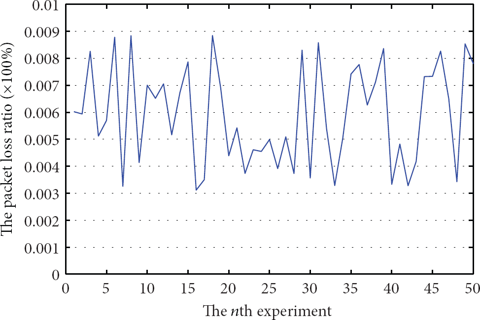
The packet loss ratios during data collection.
Although the test result about the packet loss ratio cannot reach the high requirement about the reliability 99.99%, the primary test result has achieved the desired aim of the demo prototype, since the scheme that can improve the reliability assurance from end to end has not been implemented in the common platform. And that is our next work.
5.3. Industrial CAN Data Sampling and Control
Using the prototype of the common platform, an experiment which is used to sample the voltage and current data from the industrial weld machines and control the running parameters of them is made. In the test, the management server sends a request message to all the machines for the voltage and current every 500 milliseconds. It means that the period of the data sampling is 500 milliseconds. Besides, the manager may control the selected weld machine to change its working mode and parameters, and the number of the control commands corresponding to one operation is up to 40 CAN messages; each one includes more than 16 bytes data. Moreover, all the commands for one operation are sent out in less than one second by the management server. Although we adopt the aggregation process in the access gateway, the buffer queue is also adopted to smooth the big traffic for the wireless sensor network.
In the experiment, although the sampling data is obtained with an about 1 second delay by the manager server, it does not matter to record the sampling data as the running log. And an operation to control the weld machine, through the common platform, can be finished in 2~3 seconds in the two-hop wireless sensor network.
5.4. Remote Reprogramming Sensor Nodes
In this experiment, we adopt a reprograming code with text format and 80KB size, through the proposed platform, when all the sensor nodes are reprogramed over. The average time cost is about 10 minutes. Because the reprogramming process is executed with the normal data sampling simultaneously, we limit the speed of the distribution of the programming code to 1 packet per 2 seconds. Each packet contains about 80 bytes code.
However, in each experiment, there exist ones that are reprogramed unsuccessfully. Now, we are working hard to find out the reasons.
6. Conclusion
In this paper, we present an application-customized common platform that can provide the user with a friendly web-based user interface to deploy or reprogram a running field application in VeSANs. The implementation and the simple test results basically verify that it is feasible to design a common platform to develop or deploy a new application in the presented platform in order to save the development time and the economic cost.
The main difference from other related works is the integrity and the commonality of the design and implementation of the common platform, including the implementation of the hardware and software and the real experiments and field application. And the availability of the common platform is based on the real experiment other than theoretical derivation or numerical analysis. The aim of the common platform is to set up an open environment for the developers and researchers based on the web interface. You will see our website in the near future.
However, the common platform still has many problems that need to be dealt with. For example, the reliability and the security of packet transmission need to be considered. Meanwhile, the communication efficiency still has the space of ascension and some bugs need to be fixed.
Footnotes
Conflict of Interests
The authors declare that there is no conflict of interests regarding the publication of this paper.
Acknowledgments
This paper is supported by the Fundamental Research Funds for the Central Universities (Grant no. 2013JBM001) and the National Natural Science Foundation of China (Grant no. 61201204).