
Abstract
For the safety, reliability, and fuel economy, new road vehicles and automotive pressure sensor are being equipped with tire pressure measurement system (TPMS) in the vehicle. This paper describes the theoretical analysis and linear behavior of direct-type tire pressure sensor while the vehicle is operating. A rugged pressure sensor, thin-film piezoresistive pressure sensor, design is presented as a modular design approach for TPMS, where all the main parts of the TPMS can be connected together for easiness in integration, maintenance, and replaceability. This can also result in reducing replacement cost as well as maintaining linearity behavior of pressure sensor's property. Three-dimensional model was analyzed with material properties; the resonance frequency of the model calculated is 24 kHz and sensitivity is calculated to be 1.2 µV/V·kPa. Our result shows that a thin-film technology of sensor design is still a viable solution for vehicular sensor and system measurement development.
1. Introduction
In trend of safety and reliability of automotive industry, there is a tendency to measure a pressure using special-purpose sensors which are directly integrated as a monitoring system in vehicle, known as tire pressure monitoring system (TPMS) [1]. This system involves multiple pressure sensors and components to effectively measure and inform the driver about the tire pressure. In this paper, we propose a thin-film direct-type pressure sensor based system for tire pressure measurement and monitoring to prevent some possible accident in rugged terrain with possibility of replacement of the required component of TPMS.
An act was introduced in year 2000 in USA with main purpose of vehicle safety by assisting driver with tires pressure information using TPMS. The final rule was published in June 2005 and TPMS is mandatory for new vehicles since September 2007 [1]. At the same time, in EU, the TPMS was considered a technique to reduce carbon emission and increase fuel economy (by improving rolling resistance) and safety. It is made mandatory component for all new cars by 2014 in European countries [2].
In general, there are two types of the TPMS: direct- and indirect-type monitoring system. This direct-type, or direct pressure sensor TPMS, refers to the use of a pressure sensor directly mounted on the wheels or inside tires of a vehicle [3]. The pressure inside the tire is measured using a pressure transducer with the pressure information being sent wirelessly (radio transmitter) to the vehicle to warn and/or notify the driver of under- or overinflation of a tire.
As a cutting-edge technology, earlier, indirect-type measurement was found as a quick way of implementation and uses car speed and other parameters for indirectly measuring car pressure and so forth [4]. In the meanwhile, direct-type measuring systems are mostly used in a vehicle industry today; therefore we presented a technical design and theoretical analysis of a pressure sensor for this direct-type measurement system [3, 5].
This paper gives the requirement of the direct-type TPMS technology and discusses its pressure sensor design parameters and linear behavior after we concluded our simulation results. Previous research work carried out in the field of piezoresistive thin-film and microelectromechanical systems (MEMS) pressure sensor focused on optimizing design by analyzing parameters such as doping concentration, geometries, dimension, manufacturing techniques, and diaphragm shapes. This work analyzes the traditional zigzag pattern of metal strain gauges in the thin-film and MEMS technology.
Consequently, piezoresistors resistivity changes with applied strain. The diaphragm is used for measuring the radial and tangential stresses or applied strain on piezoresistive element. The pressure sensor can be fabricated at low price in bulk quantities with reducing size and using the thin-film and rugged MEMS fabrication process. Other sensors for TPMS, accelerometer and temperature, can also be developed on the same stainless steel material in a single housing. The sensors can be attached with separate electronics and battery modules, which will allow for easy replacement of the required module, thus reducing the overall cost as shown in Figure 1.

Proposed scheme for TPMS for reducing replacement cost.
The paper is arranged as follows. Section 2 is for TPMS overview and its required system performance. Section 3 explains the pressure sensing method and data transmission; Section 4 discusses the pressure sensor design and material properties. Section 5 gives theoretical and linear analysis of direct-type senor and the simulation results are presented in Section 6 with error analysis and sensitivity in Section 7. Section 8 concludes and summarizes all works.
2. System Performance Requirements
A direct-type TPMS module is usually equipped with MEMS based pressure, accelerometer and temperature sensors, microcontroller, analog to digital converter, digital RF interface, antenna, battery, and power management system. It may and may not include an energy harvesting system [2, 6] as shown in Figure 2. Direct-type sensors are further divided into high-line system and low-line system the way they transmit the data. The TPMS system is explained in detail in [1–5, 7].

Overview of tire pressure management system.
Accelerometer is used as the wheel motion-detector, to transmit the data only when vehicle is in-motion to extend battery life. The vehicle RF receiver of remote keyless entry system is used for receiving TPMS signals; some vehicles have additional receivers for TPMS. The main purpose of temperature sensor is the correction of tire pressure measurement based on ideal gas law [3]. The circuits are designed to be ESD proof and EMC. The parameters required or TPMS design is given in Table 1 [1–6]. Special activation or trigger tool is required to force the TPMS sensor to broadcast its signal and technician uses special instruments to install and check the TPMS.
Design specification for TPMS.

On-tire monitoring system should detect within 20 minutes and warn driver when pressure in any tire is at least 25% below the car maker recommended level [1, 2].
Pressure sensor is usually manufactured with CMOS technology for low power consumption. RF transmission consumption is usually five times greater than the pressure sensing consumption. The pressure-on-demand technique is used to keep the consumption low and controlled by the vehicle controller [5].
To reduce the power consumption, all the components including the pressure sensor are designed to be the low power consumption devices. Usually all the TPMS sensors are integrated on a single substrate to reduce size and power consumption [6, 8]. The MEMS technology offers the low power pressure sensor for TPMS application mainly capacitive and piezoresistive type.
As the measured pressure is compared to the manufacturer recommendation and the instruments used for filling the pressure are not very accurate, the required accuracy for the pressure sensor can be kept high up to ±0.5 psi (3.45 kPa).
TPMS sensors can be fitted to the wheels in a number of ways. They can be mounted on the back of the tire valves stem or attached using adhesive or attached to a band which is then securely wrapped around the rim inside the tire, usually in the drop zone [6, 9]. The sensors and whole TPMS package fitted in the tire experience the environmental condition of tire, and they have to be rugged enough to survive that harsh environment especially on unpaved, gravel, and dirt road with reliable data.
3. Sensing and Data Transmission
Most of all, direct-type TPMS systems use ultrahigh (UH) frequency radio in one of the “unlicensed” ISM bands (industrial, scientific, and medical) for transmitting the data [10], often around 434 MHz (in Europe) and 315 MHz in much of the rest of the world as shown in Table 1. Some TPMS requires separate LF receiver or antenna near each wheel which can get information from each tire on demand at 125 kHz. Whilst more commonly used, at the same time, there is a single receiver which receives data from all of the wheels on the vehicle. Therefore, this receiver is also commonly used for remote keyless entry (RKE) system as this also usually uses UHF radio transmissions. Some TPMS requires the vehicle to be programmed with each TPMS serial number for identification [9, 11].
The TPMS sensor placed in the tire can be woken up from two techniques, depending on the system and circuit used. One is the LF trigger generated by the vehicle and the TPMS matches its ID to identify which tire is requested for data. Second is the internal timer, which is programmed to send the data after certain time interval. After this the accelerometer data is used to access whether the vehicle is moving or not; in case of internal timer, if vehicle is not moving then the TPMS is again put in the sleep mode as shown in Figure 3.
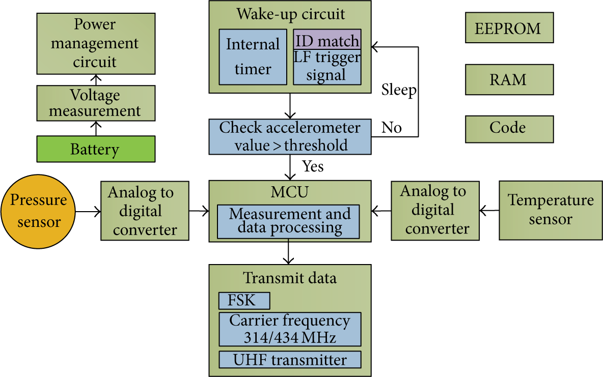
Block diagram of TPMS sensor in tire for wake-up, data measurement, and transmission.
After the wake-up process is completed the microcontroller (MCU) acquires the data from the pressure sensor using the analog to digital converter (ADC) and using the temperature information, this data is processed and transmitted in the required UHF transmission band.
The proposed pressure sensor, which is piezoresistors in Wheatstone configuration as shown in Figure 4, needs a power supply which can be supplied by a power management circuitry at the desired time. The output of Wheatstone bridge is differential voltage signal; this small differential voltage requires amplification to reach the levels required for ADC for increased sensitivity and filtering to remove the noise as shown in Figure 4. After the conversion of digital data the temperature information is used by the MCU to calculate the temperature using the algorithm residing in the permanent memory [6, 12].
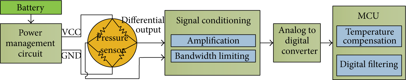
Block diagram: sensor connection for frequency band.
4. Design Properties
The accurate mathematical analysis requires the consideration of all the design parameters including nonlinearities in both temperature and material.
4.1. Sensing Methodology and Technique
Pressure sensor design consists of circular stainless steel diaphragm with a thin SiO2 insulation layer deposited at the top which experiences mechanical deformation under applied pressure. Piezoresistive materials as strain gauge are deposited in Wheatstone bridge configuration on top of diaphragm to measure the strain exerted on the diaphragm by the air pressure as shown in Figure 5.

3D diagram: view of pressure sensor.
In order to determine the optimal design of the sensing resistors including position, orientation, and length, conventional theories of solid mechanics have been investigated. Since linear response is desired, these pressure sensors are designed to be operated in the small deflection region.
4.2. Diaphragm and Insulation
The thickness of the diaphragm can be varied to match the longevity, sensitivity, and output-voltage parameters of the pressure sensor [11, 13]. Stainless steel is used in pressure transducers accommodating any media that will not adversely attack it [8, 14] such as hydraulic fluid and brake fluid. SiO2 is used as the insulating material on top of diaphragm to separate the stainless and piezoresistive layers.
4.3. Metal Contacts
Four copper contact pads are used on the piezoresistive material, two for supply voltage input and two for sensor outputs as shown in Figures 4 and 5.
4.4. Piezoresistors
The piezoresistor is designed in serpentine or zigzag pattern like usual metal strain gauge is to have a high length-to-width aspect ratio and increase resistance value. Piezoresistive elements need to have an increased sensitivity along with high conductivity for accurate measurement using bridge circuit.
4.5. Material Properties
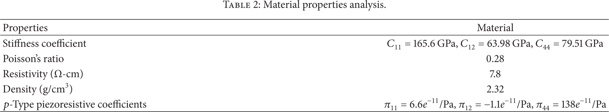
p-Type doped silicon material properties were used for simulation and analysis of piezoresistors. Stiffness coefficients
Material properties analysis.
SiO2 is used as the insulating material. Table 3 lists some properties of the diaphragm, insulation material, and metal contact pads used in the simulation.
Material properties.

4.6. Manufacturing of Sensor
The sensor is designed as a thin-film sensor, where piezoresistors can be fabricated on the ceramic substrate using silk screen printing process, but the process accuracy is limited where piezoresistor width error can be 0.5 mm. Silicon thin films are doped by ion implantation, sputtering techniques, so as to take advantage of ability to produce at wafer process.
MEMS fabrication can also be used for manufacturing and each step-by-step process (from coating, alignment, development, and bonding) is required to create mechanical structures that are essential in the microlevel fabrication techniques. A typical photolithographic process [12, 14], this technique involves developing the exposed resist; however, this MEMS design status involves a different temperature and developing time and influences the geometry and profile shape of the critical structures [16]. In addition to this developing process, a severe computational burden related with finite element simulation of strain growth, it is important that finite element meshes are not refined excessively [17].
To justify this statement further, these elements generally do not meet the incompressibility requirement associated with plastic strains. This is concerned with the required mesh refinement levels in piezoresistors geometries when modeling plasticity-induced closure under both plane stress and plane strain.
5. Theoretical Analysis
The applied pressure yields deflection of the diaphragm which leads to change in the resistivity. For instance, the thickness, t, of the diaphragm is determined by the following equation [13]:

where P denotes the applied pressure,
The characteristics of pressure sensors are signal-to-noise ratio (SNR), resolution, sensitivity, lower and upper signal limits, and so on. We carried out sensitivity analysis in an effort to determine not only a trade-off setting among the characteristics of the strain gauge but also an optimizing design of the sensor. The sensitivity which indicates the amount of the stress transmitted to the metal strain gauge through the diaphragm is analyzed from two aspects, pressure and strain sensitivities.
The resistance R of a rectangular piezoresistor is given by

where ρ is the resistivity, l the length, w the width, and t the thickness of the piezoresistor. Equation (2) enables us to calculate the resistance distribution in the sensor caused by the applied pressure. The gauge factor, G, that is, strain sensitivity, is defined as [4]
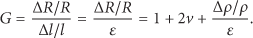
Looking into the above equation more in detail, the first two terms depend on the mechanical property of the strain gauge, which is constant. The last term comes from change in the resistivity under consideration of the strain distribution calculated in the sensor. In addition, the pressure sensitivity, S, expressed as the following is taken into account in the present study [8]:

The unit of (4) is mV/V·kPa. The equation implies a relative change of output voltage to the applied pressure. From (1) and (4), we can obtain the distribution of sensitivities and then determine the optimal design of the strain gauge.
As shown in Figures 4 and 5, the resistors form the Wheatstone bridge and output voltage is calculated as

where all resistors dimensions are chosen in such a way that they all have same nominal resistance.
The shape of the piezoresistor complicates the theoretical analysis so a coupled boundary problem for analyses of linear elasticity and electrical circuit was the main goal of the FEM simulation.
Using E (electric field) and J (current density) the electrical resistivity tensor

The relative change of resistivity d is defined as

Using piezoresistive coefficients,
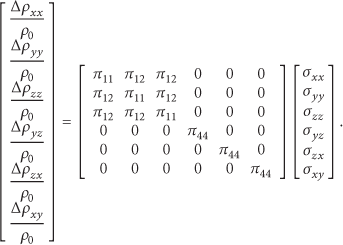
Also for FEM simulation the anisotropic elastic quantities,

6. Simulation Results
Three-dimensional model was analyzed by ANSYS FEM software [19] with material properties mentioned in Section 4. Element type SOLID226 was used for piezoresistor, SOLID231 for four metal contacts, and SOLID187 for diaphragm and insulation [6, 20, 21]. Glue command was used to bind together the elements while keeping their volume and material properties intact. Different pressure was applied at the base of the sensor and dimensional constrain was applied on the edges of the diaphragm, and material nonlinearities were not considered. The dimension of the direct-type piezoresistors was designed such that resistance in each piezoresistor is similar to other resistors in Wheatstone configuration. The thickness of piezoresistor is 10 μm, width is 100 μm, and length of each resistor is 31.18 mm. The thickness of diaphragm is 0.2 mm and diameter is 10 mm.
Different thickness of diaphragm, piezoresistive element, and insulation layer were analyzed; thickness of the diaphragm as calculated in Section 5 was chosen when minimum requirement for output voltage and signal-to-noise ratio seemed possible through available COTS (commercial off-the-shelf) electronics. Although less thickness can result in more increased sensitivity it will reduce the ruggedness of the sensor.
Sensor was supplied with 5 V DC voltage at two input copper pads. Output voltage was at remaining two copper pads as per Wheatstone bridge configuration.
Figure 6 shows the deflection of diaphragm under the applied pressure.

Deflection of diaphragm and gauge under pressure.
Diaphragm center displacement is shown in Figure 7, and the center is the point which experiences the most displacement in response to the applied pressure. Simulated differential output voltage is shown in Figure 8, and the output voltage is low which requires amplification. The design and dimension of the sensor were selected in such a way to keep the data in Figures 7 and 8 to be in linear line; this helps in reducing modular design calculation overhead and simple interface circuitry.

Diaphragm deflection versus pressure.

Output voltage versus pressure.
The output voltage can be increased by studying closely the strain formation shown in Figure 9, obtained from the ANSYS software [16, 19, 22]. The resistors positions and orientation can be changed to obtain an optimized pattern and location where all four piezoresistors in Wheatstone configuration can generate the maximum output voltage.

Total mechanical strain distribution in the direct-type sensor.
7. Error Analysis
The materials were supposed to be performed in the elastic limit [17, 19]. Uniform pressure was applied at diaphragm which resulted in the displacement in the diaphragm. Applied pressure caused the sensor to dwell like a dome causing the stresses in the piezoresistive materials [6, 16, 23].
In this case, the
The dimensions of the single piezoresistor used are

The thermal voltage noise or Johnson noise power spectral density (V2/Hz) for a single piezoresistor [24, 25] is given by

where
The

where l is length, w is width, n is doping concentration (1018),
Piezoresistors are temperature dependent; in the above configuration, all resistors will be equally affected by temperature, and therefore temperature effect is cancelled out.
In this case, the maximum allowable membrane deflection is less than 20% of the membrane thickness. Therefore, in our case, the total deflection of 50 μm is less than that. The simulation result also gave that the offset voltage arising due to difference in dimensions of designed resistors is 0.20 V.
8. Conclusions
Development of sensor and circuits for strict conformance to standards requires the understanding and knowledge of both electrical and mechanical engineering. Efficiently using the commercially available software tools as shown in this paper, we can determine the pressure sensor's linear behavior regarding electrical and mechanical property characteristics.
A rugged pressure sensor design for direct-type TPMS is presented as a computational analysis and linearity approach, where all the main parts of the TPMS can be connected together for easiness in integration, maintenance, and replaceability. The computational model and linear consideration of this direct-type sensor were investigated and the MEMS sensor structure was optimized for TPMS application; the direct-type sensor can be manufactured for rugged environment of the tire experience with linear output.
Footnotes
Conflict of Interests
The author declares that there is no conflict of interests regarding the publication of this paper.
Acknowledgments
This work was supported by a special research grant of Seoul Women's University in 2014. The author is thankful for a helpful drawing and simulation from Mr. Hamid Jabbar; Mr. Furqan Ullah, who is a formal graduate student while participating in Professor Jeong's research laboratory works, has a credit for this paper.