
Abstract
Electrochemical machining is an important method for the blade in aeroengine. Analysis of electric field in machining gap is the basis of cathode design. For solving the low precision problem for sensitive boundary which is caused by traditional numerical analysis method, this paper proposed a method of promoting the analysis precision by using the isogeometric analysis. The NURBS basis functions are used to replace the Lagrange basis function for establishing the solving equations of the electrochemical machining gap. The problem of the noninterpolation feature belonging to the NURBS basis functions, which could bring the error for imposing Dirichlet boundary condition, is settled. At last, the superiority, including precision and the rate of convergence, of the isogeometric analysis is proved by the comparison test.
1. Introduction
Electrochemical machining technology is an important method for processing complex surface (e.g., aeroengine blades). Numerical simulation method is applied to the prediction of such complex technology. The traditional methods of numerical analysis include finite element method, finite difference method, boundary element method, and so forth. Academician Zhu Di's team of Nanjing University of Aeronautics and Astronautics has been working on analyzing blade electrochemical machining and simulates processing status of interval area with finite element method [1–3]. Pattavanitch et al. established process model of electrochemical machining [4] with boundary element method. Purcar et al. analyzed corrosion status of anode workpiece with boundary element method [5]. Bieniasz established simulation model of electrochemical kinetics with finite difference method [6].
Above all, there are some common flaws in these methods: the preparation of analysis model takes long term and the mesh generation usually has poor quality. Simulation result indicates location change of unit mesh node. Fitting mesh node is required to reconstruct complex surface. Appling mesh unit of polynomial basis function to approach and indicate boundary cannot express the restriction at boundary solution area precisely in principle. It is unsuitable for solution of fluid analysis which is sensitive to boundary issues. Therefore, this paper refers to newly emerging isogeometric ideology and has established uniformed geometric model and mathematical model for simulation analysis. The study has produced numerical solution method which supports blade electrochemical machining of complex and sensitive boundary issues on the basis of interval geometrical parameterization method in NURBS electrochemical machining and application method of noninterpolation boundary condition [7].
Section 2 analyzes the research status at home and abroad; Sections 3 and 4 analyze the mathematical model of electric field of blades electrochemical machining as well as the features of machining gap geometrical and analytical model; Section 5 presents the system of ordinary differential equations to solve the potential distribution in machining gap; Section 6 elaborates the course to realize electric field distribution analysis of machining gap by the use of constant geometric method; Section 7 verifies the effectiveness of the given method through an example and makes a comparison for advantages and disadvantages between such method and classic finite element method; and Section 8 summarizes the work done and the features thereof.
2. Related Works
In recent years, the widely used design-analysis integration theories and methods have come out. The following are included. (1) Neutral format conversion: use neutral format to exchange model between different heterogeneous design-analysis systems. (2) The third-party function integration platform: use current command and secondary development to achieve the functional integration between multiple heterogeneous CAD and CAE systems, so as to make design-analysis complete the modeling and analysis optimization iteration. (3) Design-analysis integration environment: it is the most common integration method in the current commercial software, CAD/CAE software providers open their model formats mutually, and the format conversion between CAD geometric model and CAE analytical model can be completed at the background of computer so that the designers cannot feel the model difference and conversion process. In the above theories and methods, just the model differences and model conversion process are shielded from designers and a uniform working environment is presented to designers, but the various superficial problems of application caused by model separation, an essential problem, are not solved fundamentally, therefore resulting in that two sets of mathematical representation methods in geometry and analysis are used in the electrochemical machining of blades.
In terms of setting up the working model research of unified modeling and analysis, Hughes et al. [8] put forward the constant geometric method to use NURBS basis function. Such method has the following advantages: (1) geometric and mesh models are represented with the same basis function, therefore avoiding the model isomerism problem and the approximate error caused by simple polyhedral meshes; (2) there is no need to access the original CAD model when mesh refining and the model geometry information is exactly reserved, which facilitates realizing the adaptive mesh generation and the application in structure optimization field; (3) high-order coordination cell is easy to be built because of the high-order continuity of NURBS, and so forth. Although, with the above advantages, NURBS basis function lacks interpolation, the constant geometric method is hard to directly treat the essential boundary conditions. In addition, it is an urgent problem needing to be solved on how to transform the boundary model represented in format of B-Rep into the model of constant geometric method that can be analyzed directly.
In the research of applying essential boundary conditions, the methods accumulated can be divided into two types [9]: one is to correct the weak variations, mainly including Lagrangian multiplier method, correction variation principle method, penalty function method, and Nitsche method, and so forth; and the other is to correct the basis function, mainly including displacement constraint equation method, transformation method, and so forth. As for the research on essential boundary condition treating in constant geometric method, the method to directly apply the restrictions on the control vertex was presented earlier in literatures [8], and the result of monotonic convergence was achieved. However, NURBS basis function lacks interpolation and the control vertex is not certainly at the boundary, so the optimal rate of convergence is failed to be got in this scheme. Wang and Xuan [10], by referring to the transformation method thought in mesh-free method, put forward a strong applying method based on matching point—fitting the control variables by selecting a group of proper boundary matching points, to obviously improve the rate of convergence of approximate solution. Aiming at advection-diffusion problem and incompressible Navier-Stokes equation, literatures [11] presented the weak applying method of Dirichlet boundary conditions, and such method was popularized to the wall-constraint turbulence problem [12].
The transformation of solution domain to the representation applying to constant geometric method is also called parameterization of solution domain. There are related researches. Kim et al. [13] put forward the analytical method facing NURBS surface cutting. In this method, the cutting area of NURBS surface is divided into cutting unit and noncutting unit and then special integral format is built for cutting unit. The disadvantage of such method is that different integral strategies are adopted for different units and the format is complicated. Bazilevs et al. [14] put forward the T-Spline-based constant geometric method. Using the local refinement ability of T-Spline, this method is able to analyze the complicated spline model, but T-Spline is far complicated than NURBS in tensor form and the calculation efficiency is low, which is a bottleneck restricting constant geometric method applying to actual problems. Xu et al. in literatures [15, 16] put forward the computational domain parameterization method based on variational harmonic method, establishing the parametric relationship from computational domain to parameter domain through harmonic mapping and then calculating the nonlinear optimization problem to get the optimal parameterization. All the above methods have provided reference for realizing the higher-precision electrochemical machining analysis of blades under uniformed mathematical model framework.
3. Mathematic Model of Electrochemical Machining
It is commonly considered that when electrochemical machining is at equilibrium state, electric field in processing interval is steady electric field. Potential distribution complies with Laplace equation as follows:

Boundary condition at workpiece anode is as follows:

Boundary condition at cathode is as follows:

ϕ is potential value of each point in electric field; U is potential value on anode surface of workpiece; n is normal coordinate of each point on anode surface of workpiece; θ is included angle between cathode feed speed v f and cathode surface normal. v f is cathode feed speed. κ is specific conductance of electrolyte solution; κ v is electrochemical equivalent volume [17]. The model of electrochemical machining interval is shown in Figure 1.

Plane model of electrochemical machining interval of blade.
4. Principle of Isogeometric Method and Basis Function Characteristics
4.1. Uniformed Geometric and Analysis Model of Basis Function
In computer-aided analysis of blade electrochemical machining, interval between blade workpiece and cathode tool is established geometric model with CAD system. At present, commercial CAD system is adopted with nonuniform rational B-Splines (NURBS) to express blade geometric model of complex hook face. Basic idea of isogeometric method is to use the same set of NURBS basis function to express geometric model and numerical analysis model. Processing interval is presented with NURBS volumes. It is a tensor product spline defined by three knot vectors. Consider the following:

where

where {I, J, K} is index set of knot vector; {Ri, p, Rj, q, Rk, r} is basis function of univariate B-Spline corresponding to each knot vector. ω
ijk
and
4.2. Parameter Region Dividing Processing Interval Naturally
NURBS basis function is defined by knot vector and spline time(s). Knot vector of tensor product spline extends exactly as regular mesh on parameter region of processing interval. In isogeometric method, regular mesh by knot vector is applied for natural division and requires no follow-up mesh generation. The unit in isogeometric method is compared as measuring node interval (≠ 0) with reference to unit and node in classic finite element method. Such node is compared to control vertex corresponding to basis function (≠ 0) in interval. For 3D tensor product spline, the unit can be expressed as Ω e = [∊ i , ∊i + 1]⊗[η j , ηj + 1]⊗[ζ k , ζk + 1], where ∊ i < ∊i + 1, η j < ηj + 1, and ζ k < ζk + 1; it can be discovered that there is (p + 1) × (q + 1) × (r + 1) basis function (≠ 0) in unit, where p, q, and r are time(s) of basis function.
4.3. Noninterpolation of NURBS Basis Function
With respect to polynomial basis function of classic finite element, NURBS basis function has many superiorities. For example, it can indicate any geometric models precisely and achieve higher continuity at unit boundary. However, it is lacking an important property, interpolation at node, namely, parameter values at node N i (∊ j ) ≠ δ ij and ∊ j . Even if basis function of univariate spline defined by “open knot vector” can achieve interpolation at front and terminal ends of curve, it is invalid at times when extending to tensor product spline. Univariate basis function meets interpolation requirement at front and terminal ends, whereas basis function of 2D tensor product spline has no interpolation at other nodes except four angular points. Therefore, isogeometric method cannot interpolate field variables at node of blade electrochemical machining interval as that of traditional finite element method to represent Dirichlet boundary condition [18].
5. System of Ordinary Differential Equations of Blade Electrochemical Machining
The equivalent integral weak form of (1) is inferred by the weighted residual method.
Two sides of (1) multiply by weight function w equals

From the first Green equation,

where ∂Ω = Γ
a
+ Γ
b
+ Γ
c
and ∇ϕ·

The above equivalent integral form can be expressed in general form irrelevant to specific issues as follows:

where u ∈ S, v ∈ V,
NURBS basis function can be used as shape function of electric field and is discretized only in spatial domain, where

Use weight function w as NURBS basis function family and then substitute into (9) and get equation set as follows:
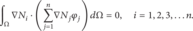
Solve and get first-order system of ordinary differential equations of potential field value as follows:

where


6. Program Implementation
6.1. Distribution of Stiffness Matrix and Load Vector
If knot vectors of parameter region at corresponding U, V, W directions of blade electrochemical machining area are [0, ∊1, ∊2, …, ∊
i
, ∊i + 1, …, 1], [0, η1, η2, …, η
j
, ηj + 1, …, 1], and [0, ζ1, ζ2, …, ζ
k
, ζk + 1, …, 1], basis functions constituted on the basis of these knot vectors shall be N
i
, N
j
, N
k
. Since basis functions have non-N
i
, N
j
, N
k
zero values only in [∊
i
, ∊i + p + 1], [η
j
, ηj + p + 1], [ζ
k
, ζk + p + 1], where basis function is adopted with 3 times p = 3 commonly seen in engineering, with local support of NURBS basis function, integral operation in (14) is unnecessary to be implemented in the whole parameter region Ω. Considering all intervals as nonzero in parameter region, Ω
e
= [∊
i
, ∊i + 1]⊗[η
j
, ηi + 1]⊗[ζ
k
, ζk + 1], Ω
e
can be regarded as isogeometric analytical unit divided by electrochemical machining interval. It can be concluded obviously that

Similar to finite element method, isogeometric analysis method can also be considered to have divided NURBS element. This kind of unit is completed when processing interval has completed modeling. Isogeometric method also experiences distribution process of one unit stiffness matrix and load vector, which is distributed to overall stiffness matrix through unit stiffness matrix. Difference between isogeometric unit and classic finite element method is as follows: (1) basis function has no interpolation property and node (fixed control point) is likely not in unit region; (2) isogeometric unit processes higher continuity at unit boundary Cr − k [19].
6.2. Processing Gap Modeling
Frontier Γ a and frontier Γ c of blade electrochemical machining gap are free-form surfaces, with the Γ b being plane. To establish parameterized geometric model, sampling could be performed in workpiece surface and cathode tool surface to find the sampling site on frontier Γ a and Γ c and then specify sampling site on Γ b based on the isoparametric condition. The parameterized model of blade electrochemical machining is shown in Figure 2.
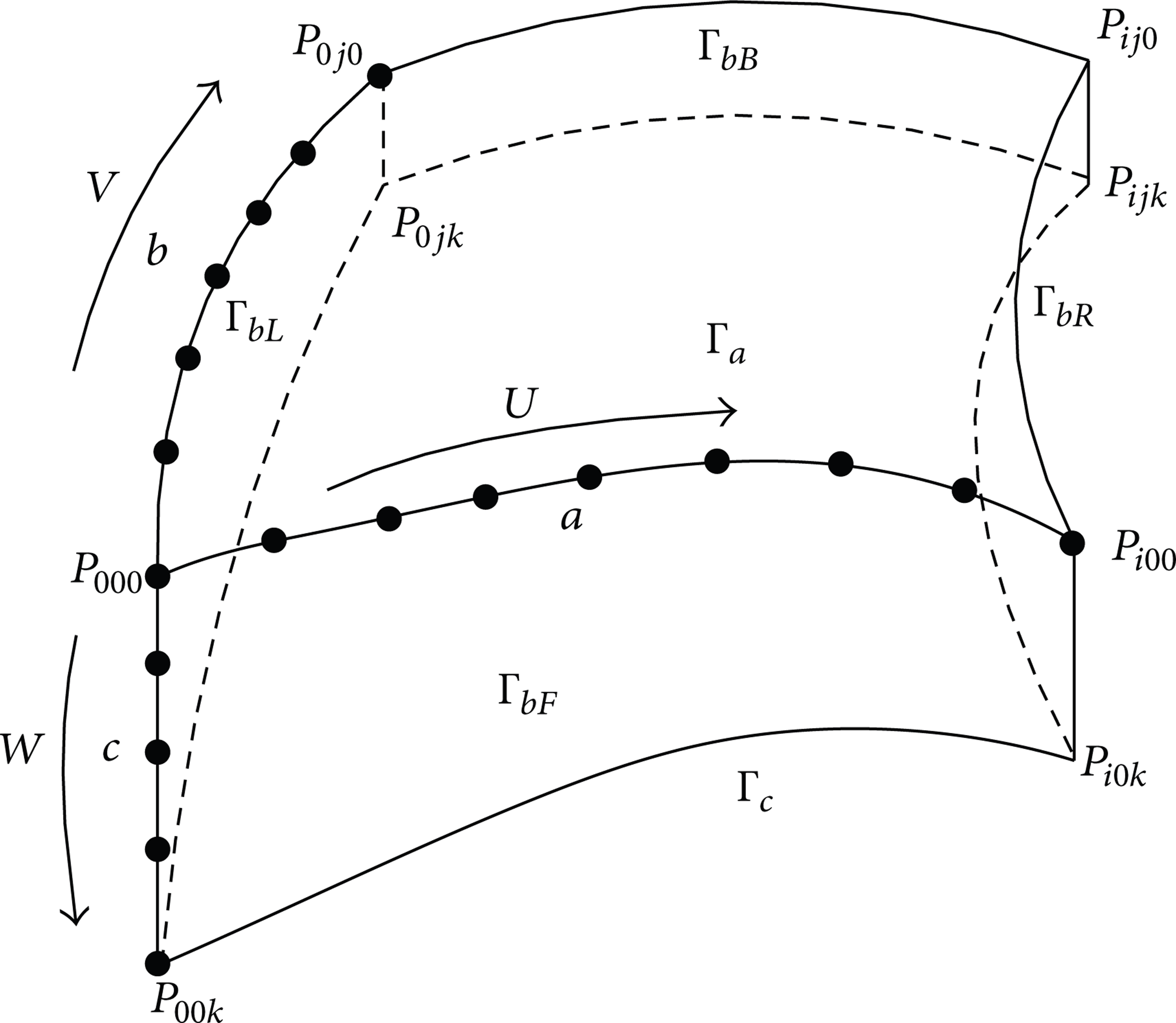
Three-dimensional parameterized model of blade electrochemical machining.
Procedures in establishing parameterized model of blade electrochemical machining are as follows.
Presume that in edges a, b, and c, of processing gap, there are sampling sites O i , P j , and Q k in directions U, V, W, among which i = 0,1, 2, …, m, j = 0,1, 2, …, n, and k = 0,1, 2, …, l.
Using cumulative chord length method, establish correspondent transform position knot vector
Optimize vector in three directions, namely, making the new knot vector fulfill
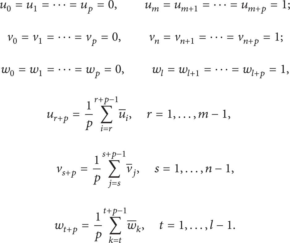
p is the number of hook face; the essay used the common number, that is, p = 3. P is the number of hook face. The essay used the common number, that is, P = 3.
Optimized knot vectors in three directions are
Reversely calculate the control point of Γ a , Γ bF , Γ bB , Γ bL , Γ bR , Γ c individually, and if the control point of processing gap frontier is Ctrl(Γ), then

where i = 0,1, 2, …, m, j = 0,1, 2, …, n, and k = 0,1, 2, …, l. P ijk is the sampling site on frontier.
The control points are transformed Vij0, Vij1, Vi0k, Vi1k, V0jk, V1jk to become the control points during the whole processing gap. Consider the following:

The last control point of blade electrochemical machining gap as V
ijk
= U + V + W − UW − UV − VW + UVW, among which i = 0,1, 2, …, m, j = 0,1, 2, …, n, k = 0,1, 2, …, l, and ∊
i
, η
j
, ζ
k
∈ [0,1]. So blade electrochemical machining gap geometric model could be taken as
Equation of anode profile is
6.3. Dirichlet Boundary Condition Handling
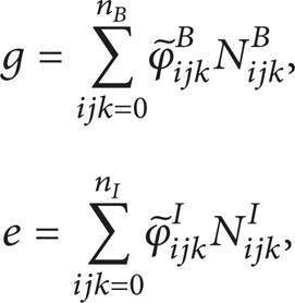
As the electric field distribution of blade electrochemical machining is expressed by NURBS basis function, it cannot use the traditional piecewise polynomial finite element interpolation way to interpolate in Dirichlet boundary to get electric field value of the sampling site. So imposing method is used to impose Dirichlet boundary condition on (12) [20]. Assume that weak solution could be sum of two parts as follows: u = e + g, among which g ∈ S and e ∈ V, and then substitute it into (9). The result could be
Assume that set for all NUBRS basis function in blade electrochemical machining gap is N = {N
t
}t = 1
n
, among which n is the number of all basis function. Assume that the set of all basis function whose value is not zero is
where

The sum number of control variate could be got after ranking the basis function. Inner control variate
7. Experimental Verification
Set the potential difference of electrochemical machining simulation as 15 V, initial electrolytic gap as 0.5 mm, and cathode feed speed as 0.5 mm/min. Electrolyte component is NaNO3, with its density being 10%, initial temperature being 25°C–30°C, and flow velocity being 15 m/s. The workpiece material is 2Cr13 steel.
The geometric model of blade electrochemical machining gap is built up by 3D product design platform NX. It is shown in Figure 3(a). The control vertexes of machining gap are reversely solved and the parameterized gap model is got by transfinite interpolation. It is shown in Figure 3(b).

Analysis and comparison of blade electrochemical machining gap's potential.
After the boundary condition is imposed by boundary collocation method, the potential distribution and electric field vector distribution are got which compare with the result by classic finite element method. It is shown in Figure 4.
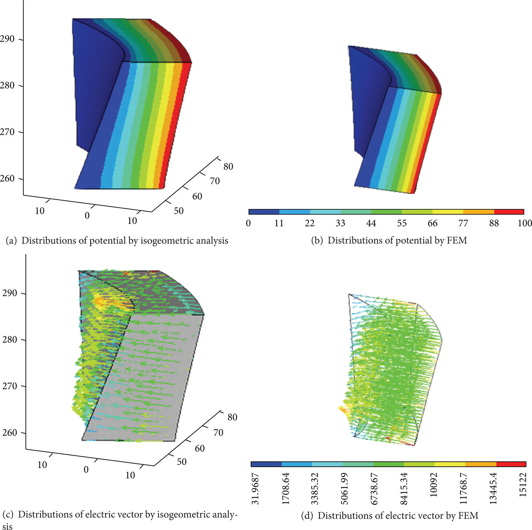
Analysis and comparison of blade electrochemical machining gap's potential.
The convergence rates of FEM and IGA are compared. Linear, quadratic and cubic functions are adopted by FEM and quadratic and cubic functions are adopted by IGA. Comparison of two method is shown in Figure 5.
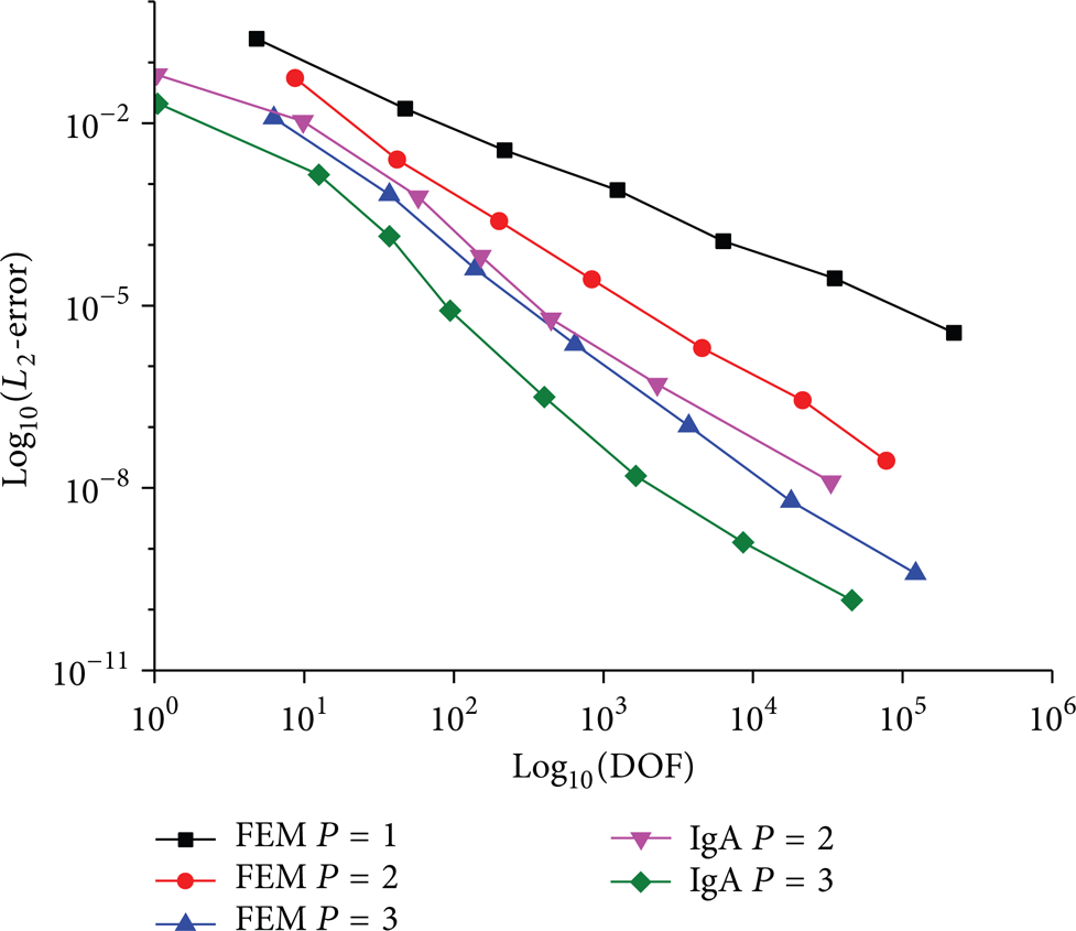
Comparison of analysis convergence rate of blade electrochemical machining gap.
Even if spline function can be interpreted as sectioned (rational) polynomial defined in parameter region, it can achieve higher continuity at unit boundary than that in classic finite element. Classic finite element often has continuous C0 at unit boundary and spline function can achieve continuous Cp − r (r is repeated times of node). Therefore, isogeometric method can achieve higher analytical precision theoretically. It is indicated in calculating data that under the condition of similar mesh freedom both FEM and isogeometric methods can achieve convergence while convergence speed of isogeometric method is obviously higher than that of FEM.
8. Conclusions
In traditional numerical analysis of blade electrochemical machining on the basis of finite element method, geometric model and mathematical description model for analyzing are different. The conversion of the two different models causes the problem of long-term preparation of model analysis and poor quality during interconversion. In addition, the fact that finite element method applies mesh unit of polynomial basis function to approach and represent boundary cannot indicate field variables distribution of electrode boundary and electrolyte boundary precisely in principle. Therefore, NURBS basis function is adopted in the paper to replace polynomial basis function. As a result, geometric modeling of blade electrochemical machining interval shares the same basis function as numerical analysis, which means modeling is completed at the same time when mesh refinement dividing. Spline unit constituted by NURBS basis function can indicate property of processing interval free curve boundary, achieving a more accurate electric field analysis in processing interval. Effectiveness of isogeometric method on numerical analysis of blade electrochemical machining is verified through living test. In the future work, the process simulation of the electrochemical base on the isogeometric method will be researched. The model conversion will be avoided in the simulation calculation to improve the computational efficiency.
Conflict of Interests
The authors declare that there is no conflict of interests regarding the publication of this paper.
Footnotes
Acknowledgments
The project was supported by the Natural Science Basic Research Plan in Shaanxi Province of China (2012JQ7002) and the National Natural Science Foundation of China (51205320).