
Abstract
Time reversal (TR), which leads various multipath signals to focus spatiotemporally on arbitrarily complex propagation environments, can resist signal multipath delay and attenuation which is caused by inhomogeneous complex environments. In this paper, the windowed time reversal (WTR) method for distance measurement between the wireless sensor network (WSN) nodes is proposed based on TR. In the WTR, the main lobe of the channel response is captured by a window. WTR not only takes advantage of the spatiotemporal focus features of TR, but also compensates the multipath effect to eliminate various factors from the environment. WTR can recover the favorable symmetry of the main lobe of channel response, thereby accurately measuring the times-of-arrival (TOA) of the electromagnetic wave and distance between WSN nodes. By analyzing the characteristics of the time reversal operator, the theoretical basis of the WTR is given in this paper. An algorithm for node distance measurement with WTR in indoor environments is described and a large number of simulations with various environments are carried out. The errors for the proposed WTR have been analyzed. Simulation results show that ranging errors by WTR are less than 1% no matter how many obstacles are in the indoor environment.
1. Introduction
Wireless sensor network (WSN) is a class of distributed computing and communication system that transmit information through an electromagnetic field [1]. The WSN nodes are usually used to perceive the various changes that concern people in the surrounding environment such as temperature, humidity, pressure, light, sound intensity, target size, target mobile, and sensitive material [2, 3]. Based on the different functions, WSN nodes are divided into sensor nodes, sink nodes, and manager nodes. Sensor nodes are randomly deployed in any monitored area to monitor important data and transmit the data directly or through the neighboring nodes to sink nodes. Finally, the data is sent to the task manager node [4, 5].
WSN avoids the complicated process of wiring and achieves the goal of continuous dynamic information collection, fusion, and transmission, as well as a number of other new fields of application. Nowadays, WSN has expanded from military to civilian areas, from industry to agriculture, from land to water, from outdoor to indoor, and from the friendly environment to the complex environment. It has become an important way to access information and has attracted a great deal of research interest during the last few years [6–8]. Moreover, the wireless nodes present some advantages in terms of system miniaturization, scalability, cost, and reduced energy consumption. Now, the research interest of sensor network related theory and the unknown node localization and tracking in complex indoor environments, such as airport lobbies, factories, showrooms, warehouses, and other information monitoring locations, is much stronger. Global positioning system (GPS) is widely used for location-dependent applications outdoors, where the devices can receive the signals coming from satellites, but GPS is hardly usable indoor. Therefore, the localization or tracking with WSN can make up the weak satellite signal strength indoors [9, 10].
It is very important to know the locations of WSN nodes to interpret the information provided by WSN nodes in a health monitoring system. A node position is known if it is manually placed, but those nodes which are randomly placed or moved need to determine its location by the localization system. So, the node localization becomes the supporting technology in WSN applications. Generally, node localization can be categorized into two groups: range-based and range-free [11]. The latter's hardware cost is low but the accuracy is poor. The range-free method is often applied to situations where node arrangement is homogeneous and the localization accuracy requirements are low [12]. The range-based method, which obtains the distance from unknown node to a beacon node directly or indirectly is usually used in cases that require high precision. The coordinates of the unknown node will then be determined by trilateration, triangulation, or maximum likelihood estimation. The range-based localization method includes the received signal strength indicator (RSSI) [13], time of arrival (TOA) [14, 15], time difference of arrival (TDOA) [15], angle of arrival (AOA) [16], frequency difference of arrival (FDOA), and round-trip time of flight (RTOF) [17]. The localization accuracy of a node in a complex indoor electromagnetic environment, which has strong multipath effects, is directly determined by the measurement methods. The localization methods mentioned above often passively avoid or minimize the effects of multipath without initiative to utilize the energy which can be gathered by the multipath. For example, RSSI usually measures the signal strength to indicate the distance, while the signal strength will change sharply due to multipath effect when some obstacles are added in the environment. Therefore, the localization accuracy of a node is greatly reduced. A reasonable way to improve the accuracy is to overcome multipath effect in electromagnetic field.
Time reversal (TR) is a unique channel matching and balancing technology, which has the ability of optimizing the channel and restraining multipath effect [18]. TR can spatially and temporally focus a peak in inhomogeneous media by absorbing all multipath energy. The more multipath due to complex environment, the better focusing result presented in comparison. If TR technique is used for the indoor node localization in WSN, it can overcome the multipath effect and improve accuracy of localization in a complex environment, which can provide technical support for the high precision of node localization.
The early TR technique is mainly focused on the application of sonic wave and ultrasonic which was first proposed by Fink in 1992 [19]. It is able to play a balance role in an inhomogeneous medium and realize the ultrasonic synchronous focusing on space and time. It has been used for detecting breast cancer and gravels in the body and so on [20]. In recent years, people have begun to research TR technology in the electromagnetic fields where they can realize the electromagnetic wave synchronously focusing on space and time, and then TR was gradually applied in wireless communication [21], underwater communication [22], ultra-wideband (UWB) communications [23], nondestructive inspection [24], target imaging [25], WSN node localization [26], structural health monitoring [27, 28], beam forming, [29] and so on.
Since 2004, many scholars tried multiple experiments to verify the focusing characteristics of TR in wireless communication [30]. In 2005, a group headed by Qiu in Tennessee Technological University measured the channel impulse response of UWB with the frequency domain method and then transformed to the time domain to study the focusing character of TR [31]. Employing the time domain method, Khaleghi et al. verified TR transmission focusing features of the monopulse in harsh multipath environments in 2007 [32]. The nodes in WSN have low power and small size. The used technical conditions are harsher than the high-power electromagnetic wave system, so the research and application of TR in WSN are very late compared to a radar system. The research results were mainly concentrated in the physical phenomena and mechanism of spatiotemporal focusing of UWB electromagnetic pulse which are based on TR [33]. Some researchers tried to apply TR technology in a multi-input and multioutput (MIMO) antenna communication system. They researched the characteristics of spatiotemporal focusing when the signal was transmitted from the transmitter to the receiver in the multipath environment. The experiment result showed that the UWB communication technology based on TR has a natural and excellent adaptability to the environment [34]. But using the focusing features of TR to research WSN, node distance measurement method has not been studied yet.
Since the existing ranging algorithm of indoor WSN nodes has low accuracy, poor stability which is extremely sensitive to the environment, WTR for distance measurement between the WSN nodes is proposed to improve the accuracy and stability in this paper. The main lobe can be obtained from the channel response of probe pulse signal by a window. The window's width equals probe pulse width, and the starting point is determined by a maximum likelihood algorithm, as the main lobe resembles the probe pulse signal. By taking advantage of the focusing features of TR, WTR can effectively and reasonably restrains the multipath effect and can accurately measure the TOA of the electromagnetic wave and distance between WSN nodes. Simulation results show that ranging error is less than 1% when nodes are line-of-sight (LOS) with each other indoors.
2. The Time Reversal Method: Theoretical Principles
2.1. Traditional Time Reversal Method
Due to reflection, scatter, and dispersion, after the transmission of an impulse generated by a transmitter, the signal a receiver obtains will contain several similar pulses with amplitude attenuation. This phenomenon is called multipath effect. If the multipath number is N, then the channel impulse response


After reversal of


If
By using a simple inequality, namely,


We can draw the following conclusions from (5) and (7). When
2.2. Proposed Windowed Time Reversal Method
The conventional TR method demonstrates the focusing ability, but the focusing time is at
After the first wave transmission process, we apply a window functions on the channel response signal to obtain the main lobe instead of propagating back the whole response signal.
The window function is

Then the new channel response


Then

From (11), it is obvious that the WTR signal is focused at time
3. Advantage of WTR in Indoor Node Distance Measurement in LOS
In the indoor environment, the reflection or blocking of electromagnetic wave by the walls and obstacles will cause received wave distortion and peak drift. The conventional method to measure the TOA by detecting the received wave's peak causes large error. The proposed WTR in this paper can recover the shape of a transmitted signal and focus the signal at TOA.
3.1. Nodes Distance Measurement Process
Assume that the beacon node (its location is known) and the unknown node are LOS indoors. The ranging process based on WTR is shown in Figure 1.
The unknown node sent the probe pulse by broadcasting. According to the characteristics of the TR operator, the probe pulse must use an even function in order to achieve the effect of focusing; Gaussian pulse of even-order derivative function is an even function in which the original function has only one wave trough without the peak; the second order derivative function has a peak and two symmetrical wave troughs; the fourth order derivative function has two symmetrical peaks and a wave trough. In order to better adapt to the multipath environment and good anti-jamming capability, the second order Gaussian pulse is used as the probe signal in this paper. The waveform is shown in Figure 1(a). The beacon node received the impulse response of the channel, as shown in Figure 1(b). In channel response, there was a peak near 6 ns, followed by a smaller peak near 9 ns, which is produced by walls or obstacles reflections. It verifies that the propagation of electromagnetic waves indoors is not ideal. The impulse response of the channel contained several side lobes in addition to the main lobe which evolved to the similar asymmetric Gaussian third order derivative function. Main lobe was obtained by a window, where the window width was the same as the original probe pulse's width, as shown in Figure 1(c); maximum likelihood algorithm was applied to find the starting point of the window. The principle of maximum likelihood algorithm is to find the correlation between probe pulse and the pulse response. The time for the maximum value of the correlation is defined as the window's starting point. By using this window, the main lobe ultimately resembles the probe pulse. The windowed signal was time-reversed and then was back propagated to the unknown node. The unknown node would receive the focusing signal, as shown in Figure 1(d). Figure 1(e) shows the waveform of a focusing signal. Its main lobe is an approximate axial symmetry pulse and it is very similar to the second derivative function of Gaussian pulses. The electromagnetic energy is concentrated in the main lobe. It indicates that the windowed TR also has a good focusing effect and excellent restoration to the original probe pulse, while maintaining a smooth peak. It is easy to obtain the TOA of a wave by using the focusing time. The distance between the beacon node and the unknown node could be calculated by TOA and electromagnetic wave velocity in air. In Figure 1(f), we show an example measurement result for the distance between beacon node and unknown node located in a simulated 2000 mm × 2000 mm 2D indoor space without any obstacles. The simulated indoor environment platform will be discussed in detail in Section 3.2. The measured distance by the proposed WTR method was 1501.6 mm when the actual distance was 1500 mm. The absolute error and the relative error were only 1.6 mm and 0.1%, respectively.

Distance measurement with WTR.
3.2. Establishment of Indoor Electromagnetic Simulation Environment
In order to verify the ranging effects of WTR, we use MATLAB to build a visual simulation platform which is based on the finite difference time domain (FDTD) method. This visual simulation platform is used to simulate the electromagnetic field indoors. The main idea of FDTD is that the field is scattered on the time axis and spatial axis, using central difference instead of a partial differential, then it turns Maxwell's equations into differential equations by adopting the leapfrog method on the time axis and spatial axis to solve equations gradually. Finally, we can obtain a discrete solution of the space electromagnetic field in some boundary and initial conditions.
Due to the limitation of computing speed and storage capacity of computer, the FDTD method is not suitable to simulate electromagnetic scattering for high frequencies (or big goals). Therefore, we started the simulation experiment in simplified 2D space. In simulation, we used dipole antennas, which are perpendicular to the 2D plane as transmitting and receiving antennas. In addition, the center frequency of a probe pulse is 2.4 GHz and an infinite length square column is used to simulate various obstacles to generate a strong multipath effect, and the MUR second order boundary is used to truncate the simulation space.
3.3. The Impulse Response with Small Obstacles in the Room
In this paper, an object is defined as a small obstacle when its reflection length is less than 2 times the wavelength (250 mm) in the horizontal plane. The small obstacles (sectional dimension is 200 mm × 100 mm) were placed on the different locations near the beacon nodes at different times (including one side, two sides, inclined front, and back of beacon nodes). The real distance between beacon nodes and the unknown node is 1500 mm. The unknown node sent out a probe pulse; then the channel response received by beacon nodes was represented in Figure 2 as follows.
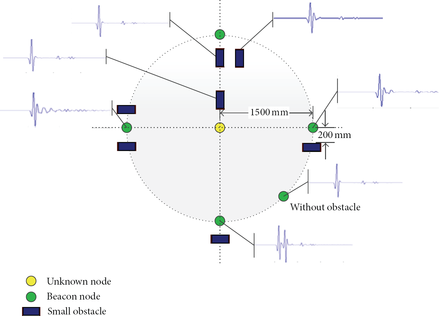
The channel responses with small obstacles at different location.
When the distance between nodes is 1500 mm without any obstacles in the indoor space, the main lobe of impulse response was distorted like a third order Gaussian pulse, where the second wave trough's amplitude was larger than the first trough. Meanwhile, the side lobe signal was very weak. When small obstacles were placed in different locations near nodes, it was apparent that different levels of multipath effects were observed. When an obstacle was at the extension line of sight, as the bottom beacon node in Figure 2 shows, the multipath effect was the most obvious because reflection of electromagnetic waves from a small obstacle was significantly strong.
Figure 3 illustrates channel pulse response when small obstacles were placed parallel or perpendicular to the LOS in different positions. When the small obstacle moved horizontally towards beacon nodes, the multipath effects were stronger in the cases where the obstacles were next to nodes than in the cases where the obstacles were in the middle of LOS. When an obstacle was moving away from the node along the perpendicular bisector of LOS, the multipath effects would cause an increase of the second half-wave of the main lobe's amplitude. When the obstacle was just on the LOS, the received signal was obviously obstructed (peak delay, small amplitude).

The channel response of different locations in different distances.
From the two sets of simulations above, the small obstacle in the common place has less influence for channel response than the wall. However, when it is closed to special place such as around nodes, the multipath effects cause the electromagnetic wave to be superimposed in the same direction, which makes the peak of the main lobe offset and the second half-wave amplitude increase.
3.4. The Impulse Response with Large Obstacles in the Room
Figure 4 shows the effect on channel response while the single large obstacle (the length is 4 times the wavelength) was placed in different places separately. From the signal response, it is easy to discover the following.
When the obstacle was on LOS, the impact on channel was the greatest. The peak's amplitude was smaller and it lagged obviously and some obvious side lobes occurred. When the obstacle was on an extension line of LOS, the amplitudes of the two peaks were similar which was difficult to distinguish from the main lobe. The distance between two peaks is proportional to the distance between obstacle and node. The level of reflected waves by obstacle was equal to the level of direct wave, possibly even stronger than the direct wave. It indicated that there was a greater impact on the channel when obstacles were collinear with nodes. When the obstacles were placed perpendicularly to the LOS (bottom obstacles), the side lobes were weaker compared with the main lobe. The multipath effects were not strong. The changes of the impulse response by the obstacles were not apparent. When the obstacles were parallel to the LOS (top obstacles), the effect of multipath was similar to that by small obstacles at the same positions.

The channel response of large obstacles in different locations.
From the above analysis, obstacles in the room will distort the impulse response signal, and it is difficult to find the time of arrival by using this impulse response. The proposed WTR can correct the transmitted channel regardless of the obstacles.
3.5. The Channel Correction of Time Reversal
The multipath effects cannot be avoided with existence of obstacles in the rooms. Our proposed WTR can apply the multipath effects to focus on and correct the distorted signal. We randomly pick up two cases with small obstacles and two cases with large obstacles from Section 3.4 cases to demonstrate our WTR ability to restore the probe signal's shape as shown in Figure 5. In Figures 5(a) and 5(b), the channel impulse responses and WTR responses were compared for the cases with small obstacles. The main lobe of the channel response of probe pulse was obviously deformed and it was asymmetric. The side lobes with small amplitude also showed the same deformation. On the contrary, the main lobe of the focusing signal by WTR was restored to the original symmetrical second order Gaussian pulse (probe pulse). The main lobe's energy was concentrated and the peak was clearly displayed. In Figures 5(c) and 5(d) for the large obstacle cases, the WTR also shows similar restoration ability.

Comparison of channel correction for different channel responses.
The ability to restore the shape of a probe pulse and focus the energy at a peak is the key for WTR to correctly measure TOA, thus measuring the distance between nodes regardless of complex environment.
4. Simulation Environment and Results
4.1. Simulation Environment
The reliability, ranging accuracy, and robustness of WTR algorithm are tested by setting different medium environments including the size of indoor area, the location of unknown nodes and beacon nodes, and the size and the cross-section shape of obstacles. Because FDTD needs a lot of computing resources to seek the discrete solution of space electromagnetic field and the CPU speed and memory of the computer are limited, the test room area in our simulation is limited to 9 m2. The electromagnetic wave's center frequency is 2.4 GHz. Nodes should not be placed near the wall and the corner; obstacles with 3–7 different sizes were generally chosen randomly. Figure 6 is one of the simulation environments we ran for node distance measurement. The indoor area was 2.6 m × 2.6 m, the node distance was 1.5 m, and five small obstacles and two large obstacles were randomly placed in the room.

A typical environment of distance measurement.
4.2. Simulation Results with Nodes Fixed in Different Environments
The simulation environment was 2.6 m × 2.6 m and the node distance was fixed to 1.5 m. Obstacles with different sizes and numbers were randomly placed at random locations, which were defined as different cases. At each case, we performed WTR to measure the node distance. 40 sets of experimental data had been measured. The measurement errors are given with red color in Figure 7. There were 33 sets of experimental data where the measurement deviations were ±1.56 mm and the relative error was only 0.1%. They might be caused by computing error when the simulation grids of the test areas were divided. The other 7 sets of experimental data had different measurement errors. The maximum error was 10.94 mm among them (the relative error is 0.72917% correspondingly). The experimental records show that there were 5 negative deviation datasets because the obstacles were too close to nodes. The other 2 positive deviation datasets were caused by obstruction which was close to the LOS. The blue curve represents the relative error whose maximum value was only 0.72917% in Figure 7. The group of experiments shows that the proposed WTR has the character of high accuracy, good stability, and repeatability.

The error of measurement when the distance of nodes is 1.5 m.
4.3. Simulation Results with Different Node Distances and Different Environments
The unknown nodes were placed statically at the side of the test area which had a size of 2.6 m × 2.6 m. The beacon node was moving away from the unknown node. The distance range was from 0.3 m to 2.4 m from unknown nodes. 3–5 obstacles were placed randomly in the test area. 38 sets of experimental data were obtained with the analyses of the absolute and relative errors, as shown in Figure 8. 35 groups (90% of total) performed absolute errors within 10 mm. The statistical results show that the average absolute error was only 5.37 mm, the standard deviation was 0.0058, the slope (slope = 0.00309) and the intercept (intercept = 0.00563) of linear fit for absolute error were both tending to zero, the relative error (in addition to a point distance of less than 0.5 m) was within the ±1%, and the average relative error was 0.4387%. It shows that the test error was not proportional to the distances of nodes. On the contrary, the relative error tended to be stable with the increase of distance. It also verifies the reliability and robustness of the WTR algorithm.

The error of different distance and different environment.
For further study on different distances and different environments which influence the ranging algorithm of WTR, we placed nodes with distances from 0.5 m to 4 m with an increment of 0.5 m. At each distance, we placed the obstacles randomly for 10 times, which represented 10 environments. At each distance and each environment case, we performed WTR to measure the node distance. Figure 9 shows the measured error for the 80 groups simulations. The maximum relative error was 1.5625% (the corresponding absolute error for 0.03906 m). Only two sets of data errors were more than ±1%. The rest of the relative errors, which accounted for 97.5% of all the experimental data, were within ±0.9375%. This shows that the WTR algorithm has very strong adaptability, good robustness, and high measuring precision.

The 3D error bars of environmental adaptability.
4.4. Window Size and Starting Position Effects
By (11), the position and the size of the window can directly influence the focusing peak position of the main lobe. We performed a simulation about the effects of window size and position on TOA. In Figure 10, The waveform (a) was the focusing signal with correct window. The waveforms (b) and (c) were the focusing signals where the window moved, respectively, forward or backward for 50 sampling periods. Because the window did not fully cover the main lobe of channel response at the wrong position, it resulted in that the main lobe of the focusing signal was incomplete and asymmetric and the position of the peak point was shifted with the same time in the reversal direction of the window's shift. The waveform (d) was the focusing signal that the window widened to include the first side lobe and the main lobe of channel response. The focusing effect was quite good and the main lobe was symmetrical. Also, the first side lobe perfectly reappeared, but the position of the peak of the main lobe off-sets its right position. The waveform (e) was the focusing signal such that the window was narrow with 30% off, the main lobe was mildly asymmetric, and the peak point offset would cause ranging deviation.

Window size and starting point effects.
4.5. Error Analyses
According to the above different experimental error results, the ranging error of WTR was mainly rooted in the following aspects. Firstly, the meshing of the test area is too large (the wavelength of 1/20). The nodes at different locations in the same grid will present same results, which was called calculation error. Secondly, the channel impulse response deformation, which was caused by the multipath effect of the indoor environment on electromagnetic waves, leads to offset of the window position of the WTR algorithm and causes measuring error. This error can be actually compensated by adjusting the window position. The compensation dosage is related to the specific indoor environment. When the algorithm is used in a real environment, the environment can be tested by directly measuring the known nodes distance to find the optimal window position for compensation dosage. It will further improve the accuracy of the algorithm. Thirdly, the system sampling rate limitations also resulted in error. The sampling interval should be minimized as much as possible to reduce range error.
5. Conclusion
The proposed WTR method can realize the spatiotemporal focusing which can effectively collect the multipath interference energy, improve the signal-to-noise ratio and reduce intersymbol interference in arbitrarily complex and inhomogeneous environments, therefore effectively resisting signal multipath delay or attenuation which can significantly influence the transmission characteristics in the general system. In this paper, WTR applies the multipath compensation principle and greatly improves the ranging accuracy of WSN nodes in complex environments. The ranging method of WTR can not only maintain good environment self-adaptation with spatiotemporal focusing characteristics but also realize precision compensation by adjusting the position of the window to ensure the ranging accuracy without increasing the complexity of nodes (add time synchronization modulation, etc.). A large number of simulation experiments show that the ranging algorithm of WTR is robust, feasible, and stable. Additionally, the ranging accuracy is as high as 1% in LOS and satisfies the requirements of the actual ranging.
Footnotes
Conflict of Interests
The authors declare that there is no conflict of interests regarding the publication of this paper.
Acknowledgments
This work was supported by the National Natural Science Foundation of China (Grant no. NFSC #51174084 and Grant no. NFSC #51121005), the National Natural Science Foundation of Hubei Province (Grant no. 2010CDB02504), the Foreign Scientific and Technological Cooperation Project of the Science and Technology Department of Hubei Province (Grant no. 2012IHA00401), and Backbone Teachers Research Abroad Program of Hubei University of Technology.