
Abstract
Geometrical defect is one of the main problems that will affect performance and perfect mating of produced parts. Coordinate measurement machine (CMM) is commonly used for the measurement, but the use of this machine is limited because of the small size and complexity of the component or features. This study aims to evaluate the defect that occurs on an AA6061 cold forging blade produced using cold forging process based on profile measurement technique. A systematic approach based on focus variation was proposed to evaluate two features, that is, roundness error and twist deviation. The profile was obtained with the use of InfiniteFocus Alicona 3D surface measurement system. Specific algorithms were developed for different cases as the evaluation of the features is discrete and the results were validated.
1. Introduction
Assembly accuracy depends on part quality, but defects damage part quality and its accuracy [1]. Accuracy is very crucial in manufacturing near-net or net-shape parts with complex profiles. The main goal of net-shape manufacturing is achieved when components are allowed for assembly without requirement of secondary processes such as machining [2]. Therefore, it is essential to detect and prevent the defect as early as possible during the production process. Cold forging, one of the net-shape manufacturing processes, is governed by many factors such as friction, part geometry, die shape, and temperature setting of the die and workpieces. Hence, the cold forging process has a high tendency to form defects. Arentoft and Wanheim [3] classified forging part defect into six: fold, shear defect, surface defect, form defect, crack, and structural defect. Causes of defects include die deflection, yielding or wear, and eccentricity or buckling due to flow imperfection. Kimura et al. [4] evaluated component assembly based on shape error. F. C. Lin and S. Y. Lin [5] studied the folding defect during the cold extrusion of aluminum. The relationships between defect and geometrical shape were studied based on the radius ratio. A similar approach was employed to investigate the barreling formation during cylinder upsetting with hollow die [6]. Metal flow imperfection related defect has attracted the attention of many researchers. Chan et al. [7] proposed a dynamic change of tooling geometry to control the most common flow-induced defect such as folding. Other defects such as die filling and barrel formation during the lateral extrusion process have been discussed by Tahir [8]. Similarly, Liu et al. [9] studied the underfilling problem in the rotary rolling of a flange. On the other hand, Narayanasamy et al. [10] studied the reaction of various metals to barreling during the cold upsetting process. In his study, unlubricated truncated cone billets were used as a case study, and the relationship between the measured radius of curvature of the barrels and the stress ratio parameter was established. In addition, Baskaran and Narayanasamy [11] applied white grease as a lubricant to determine the dimensions such as height, contact, and bulge diameter at different stress-ratio parameters. Yilmaz et al. [12] conducted an experimental investigation of conventional closed-die forging to study the effect of aspect ratios and indentation to the forging load and die filling. Lu and Zhang [13] found that forging defects are caused by improper die dimension. Their study was carried out, taking into consideration the temperature dependency of the thermal and mechanical properties of materials. Song and Im [14] studied the effect of process design parameters on the formation of underfilling and folding defect during closed-die forging of bevel gears. In another study, it was proposed that, by optimizing process sequence, surface defect can be solved [15]. On the other hand, Qamaz investigated the effect of shape complexity and dead metal zone on the quality of cold extruded part [16]. In addition, Sheu and Yu [17] introduced a new type of die design to solve the folding defect during the orbital forging process. The new design influenced the flow of the preform, resulting in lower tool stresses and preventing the folding problem. Sun et al. [18] studied the material flow behavior of magnesium alloy in the formation of hook, sidewall, and boss during the press forging of notebook cases. They introduced methods to prevent the material from flowing outwards, which causes the geometrical defect.
Noncontact methods such as vision system and image processing techniques are among the most recent approaches. They offer systems that are consistent, accurate, and highly repeatable [20]. The noncontact method produced better result as the probe size limit effective measurement compared to the lens used in the noncontact method, which is more focus as illustrated in Figure 1. In addition, the application of contact method such as CMM is also limited by the size and characteristics of the hole, as shown in Figure 2.

Comparison between (a) tactical and (b) optical surface measurement methods to (c) the measured surface [19].

The problem faced while using CMM: (a) small diameter and (b) inconsistent depth [19].
For circular features or component, defects such as out-of-roundness (outer or inner) may affect the quality and accuracy of assemblies [21] and fatigue life of the hole [22]. Roundness variations or out-of-roundness can be measured from the maximum inward deviations of the part's profile from the minimum inscribed circle. Roundness errors or out-of-roundness can be defined as the minimum radial separation of the bounding concentric circles, which contain an actual boundary of a measured section of manufactured workpiece [23]. Perfect roundness is the condition in which all surfaces of a circle are identical or equidistant from the center point or axis. Typically the evaluation process can be categorized into two stages, begin with data collection from the scanned image, and end with roundness measurement. There are two types of data collection methods, that is, contact (tactical) and noncontact (optical). In most cases, a contact method such as coordinate measurement machine (CMM) is used in the data generation stage in the form of a Cartesian coordinate [24]. Once the coordinates are obtained, the parameters of the best-fitting geometrical features can be evaluated [23]. However, the system requires high-precision setup and is time consuming [25].
In evaluating roundness error, for example, researchers emphasize the development of fast and efficient algorithms or approaches. For example, in dealing with a large number of points gained from a profile, especially from CMM, Gadelmawla [21] introduced a simple and efficient algorithm to evaluate the roundness error. The software is developed based on three criteria: maximum circumscribing circle, maximum inscribed circle, and least square circle. Li and Shi [23] used curvature techniques to evaluate roundness error. In their study, the computational geometrical concept of convex hulls is exploited to reduce computations. Other techniques include employing computational geometry, such as the application of Voronoi diagram [26, 27] and the introduction of outer and inner convex hulls to simplify evaluation [28]. Huang and Zheng [29] evaluated roundness based on area hunting. However, Wen et al. [30] proposed a method to unify all four models of roundness by employing genetic algorithm. Integration can be achieved through formulation of the objective function of the models, and then the initial populations are generated to solve this problem simultaneously. From the literature, no effort has been made to measure the roundness based on profile deviation gathered from optical method. In practice, various engineering components have been produced through forging or machining processes that involve roundness, such as cylinder bores and connecting rods. Measurements are typically performed to evaluate the roundness as a result of tool wear and chattering in machining of hole [31] and hole punching [32] after use for a period of time. Roundness has become one of the quality measures of parts [33]. Therefore, it needs to be evaluated rapidly and accurately.
The paper presents an introduction, and then the concept of surface measurement technique based on focus variation is explained. The problem statement is outlined, followed by the methodology of the study. The result is then discussed and a case study of cold forged propeller blade was performed to clarify the developed technique. The paper ends with conclusions.
2. Focus Variation
Focus variation is a method that allows the measurement of a real surface topography with the use of optics with limited depths of field and vertical scanning [34]. In focus variation, the depth is determined through a search of the best focus position of an optical element pointing to a sample related to a certain distance from the depth value. The conduct of this procedure for many lateral positions results in the construction of a depth map. The diagrams of the Alicona system and the mechanism of focus variation are shown in Figure 3. The process begins as the white light from the light-emitting diode source is transmitted through a transparent mirror and the objective lenses to the sample. Because of variations in the topography and reflectivity of the sample, light is reflected in different directions. The reflected light is partly collected by the objective and projected through a semitransparent mirror and the tube lens to the charge-coupled device sensors. To measure the focus, the standard deviation of the grey values of a small local region can be calculated using this equation [35]:


The coordinates system of the Alicona and mechanism of scanning.
The amount of focus, F z , is a function of a focus measure, FM to the region operator reg w (I z ,x,y), which extracts information from I z at the lateral position (x,y) over a certain rectangular region of w × w pixels. The content of the I z at height z is used an input. In order to make sure that the captured images are correct, the operator needs to make sure correct positioning and coordinate system, which will be further discussed in Section 4. Furthermore, for each measurement results, both measurement value and the measurement uncertainty will be provided. This can increase quality and validity of the measurement value.
3. Case Study
A propeller blade has a complex shape and typically comprises four parts, namely, the suction face, pressure face, leading edge, and trailing edge. In addition, there are other features that need to be added to the blade for assembly purposes [36], that is the pin head. In autonomous underwater vehicle assembly [36], which consists of the blade and hubs, the blade needs to be sandwiched between the rear and front hubs, as shown in Figure 4. The head has direct contact to the hub, so the quality of the hole is crucial to ensure perfect mating between the two parts. In contrast, the accuracy of the pin head is not critical as the shape will deform according to the cavity, as shown in Figure 5. Therefore, the roundness of the pin head is assumed to be perfect. The main problem is the hole produced on the front hub involved in the assembly. The size of the hole is considerably small and has inconsistent depth. Therefore, the use of CMM is quite limited, and setting up the machine is time consuming. In addition, the complex profile of the blade causes difficulties in the fixturing and in determining the reference points or surfaces.

Final assembly of the AUV propeller.

The embossing tooling of the blade.
The formation of twist bending is one of the primary sheet-forming processes currently employed by major automotive industries. However, the process results in a severe springback problem, which affects the accuracy of the finished part. Although springback is considered a manufacturing error, its proper assessment and precise control have been a rather challenging task [37]. This is because springback will affect the twist angle of the blade, which directly is related to the performance of the propeller [38]. A number of studies have already been conducted on the springback problem, but none have focused on the twist springback that involves thickness changes or thinning. From mechanics point of view, the twist springback results from torsional moments in the cross section of the workpiece. The torsional displacement develops from the unbalanced elastic deformation and residual stresses acting in part to create a torsional moment, which tends to rotate one end of the part relative to another. The torsional moment can originate from the in-plane residual stresses in the flange, in the sidewall, or both [39]. In the production of a propeller blade, bending twist forming is commonly used to produce the twisted shape of the blade.
The springback is measured based on twist angle deviation and can be defined as β b − β d , where β b is the twist angle of the blade and β d is the twist angle measured on the punch. The twist angle β is defined in terms of the chord line with respect to the horizontal line, and blade twist angle defines the pitch settings at each position along the blade according to local flow conditions [40], as demonstrated in Figure 6. The chord length can be defined as the distance between the trailing edge and the point on the leading edge. Given that the twist angle varies along the blade, therefore for 2D investigation, the blade is cut into few sections, as shown in Figure 7. Makem et al. [41] defined the similar phenomenon as twist deviation. Figure 6 shows the coordinate system of the blade and to ensure correct measurement, both blade and measurement equipment coordinate system must be the same.

The definition of the twist angle and chord length.

Five sections of the blade.
4. Methodology
The methodology can be described into two stages. In the first stage, the scanning and mapping procedures of the profile are same. In the second stage, due to discrete features, specific algorithm was developed. The first stage begins with the construction of profile from scanned 3D surface. For scanning, the studied parts will be placed on the table, and lens with 2.5x magnification (vertical resolution of 2300 nm). Note that the magnification level will affect the quality of the scanned part and the time required for scanning. For this case, lens with 2.5x magnification is enough as recommended in the manual. The part is placed onto the motorized stage and for the blade, which is not flat, plasticine was used to avoid unnecessary movement during scanning. One of the advantages of Alicona system is a technology, namely, SmartFlash Technology, which will ensure quality and reliability of the captured image at minimal part setting up. The resulted profiles can be converted into z-x coordinates, which then plot in Excel sheet.
4.1. Roundness Error
The raw data of the hole profile obtained from the scanning is in 3D. For roundness error measurement, which involved four stages as illustrated in Figure 6, the data then need to convert into 2D. Begin with the construction of at least three straight lines (nline ≥ 3) that intersect at the center of the hole (Figure 8(a)). Intersection point at the center is assumed to be the center of the hole. Note that, for reference, the length of the lines must not exceed the nominal diameter of the hole, which has been determined from the mapped profile as shown in Figure 8(b). In addition, based on that reference, point at edge of each line will be determined named point cloud. Then, point cloud will be determined at the intersection between the constructed line and hole radius after the lines were deleted as illustrated in Figure 8(c). Using the MZC rules, the maximum and minimum radius as well as roundness error can be determined as shown in Figure 8(d). A simple programme has been developed using Matlab to automate this task, begins with the construction of the lines until determination of the center and radius of the hole. The nominal diameter of the hole is 1.0 ± 0.1 mm. The flowchart of the approach can be summarized in Figure 9.

The steps in determining roundness error.
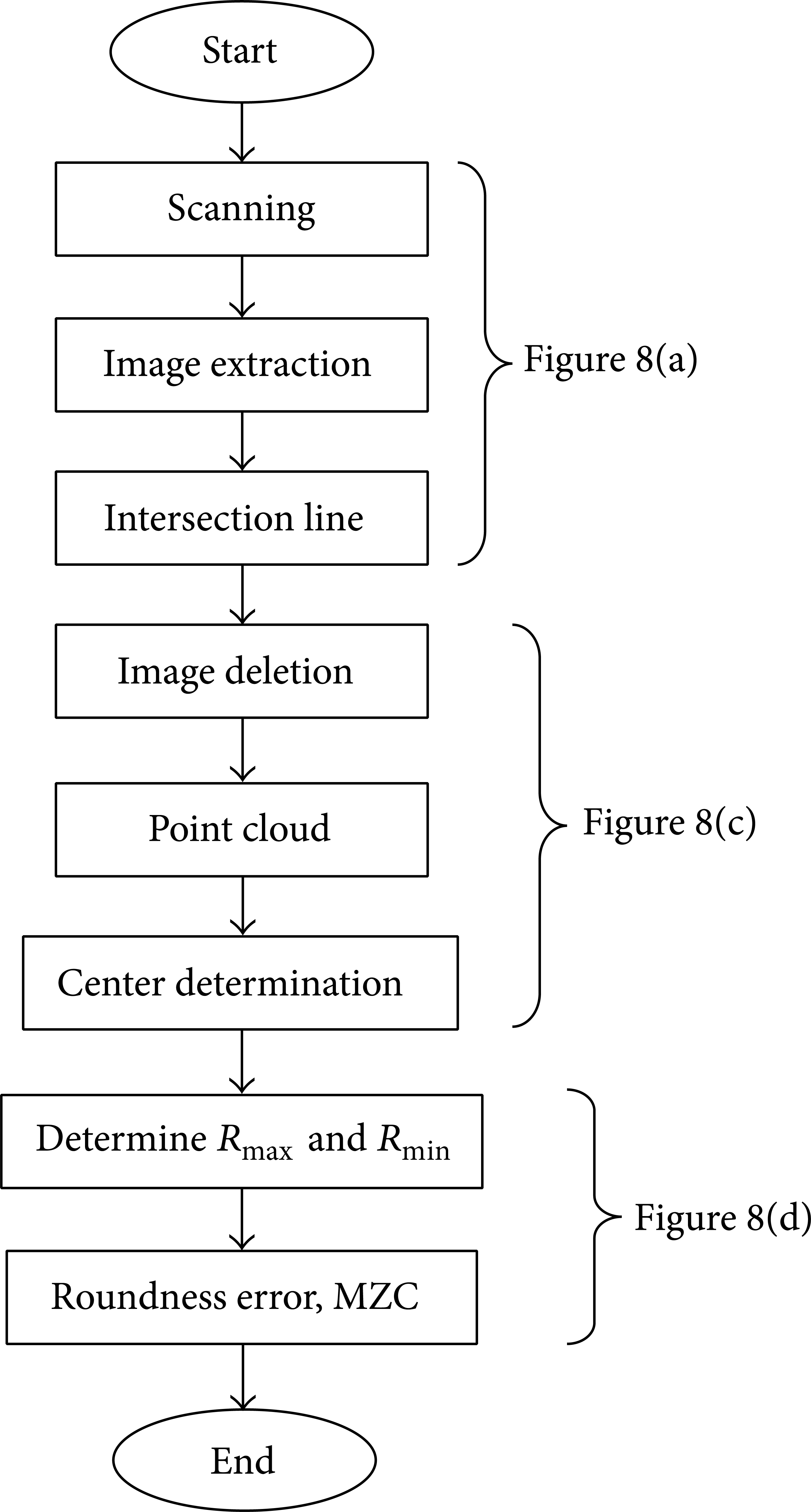
Flowchart for the roundness error determination.
Since the holes are made through embossing process, the problem or situation where the axial axis of the hole deviates from the scanning direction is slightly less, but the main problem that usually occurs is nonflat surface due to part tilting during forming process.
4.2. Twist Springback Measurement
The process begins with the filtering stage, where all undesired data or noises are deleted. In this case, noises depict the defective data that resulted from unexpected measurement error. The twist angle deviation is determined by comparing between two profiles which is in contact during forming process, that is, the die profile (profile d) which represents the targeted profile and the blade profile (profile b) which represents the manufactured profile. But the resulted profiles are at different direction curvature: one of the constructed profiles is in concave while another is in convex shape. Therefore, an algorithm is required to translate one of the profiles, which can be systematically compared. In this paper, the double-mirroring technique is proposed. The mirroring is performed on each point that comprises the profile. The steps of the mirroring algorithm are given below. The algorithm begins with determination of the midpoint (m x ,m y ) of the profile, which is half of the chord length. Next, the selected point in vector unit will be computed. After mirroring from the midpoint, new translated point will be defined (x2,y2). The proposed algorithm named as double mirroring as the mirroring steps is repeated twice in order to complete the task. Figure 10 demonstrates the steps as follows:
determination of the midpoint
(m x ,m y ) = half of the chord length;
computation of the vector of point
d x , d y = (x1 − m x ,y1 − m y );
applying first mirroring, 180 degrees from the midpoint
dx1 = − d y and dy1 = d x ;
determination of new points
x2 = m x + dx1 and y2 = m y + dy1;
repetition of the same steps for all points.

Example of the mirroring technique for one of the points.
After the completion of the mirroring process, the deviation can be measured. In this approach, the intersection of both profiles is equal to half of a chord length, that is, the mid-point which is assumed to be fixed for this case. A straight projection line can then be drawn between two points defined on both profiles, projection line b for the blade and projection line d for the die as shown in Figure 11. The starting and end points of the line must be at the same distance from the midpoint. The angle of both profiles can then be determined. This approach has been modified from the technique initiated by Makem et al., [41]. Notably, both projection lines must be intersected at the same intersection location and initial profiles. Finally both twist angles, twist angle for the blade, β b , and twist angle for the die, β d , can be defined before the twist springback can be determined.
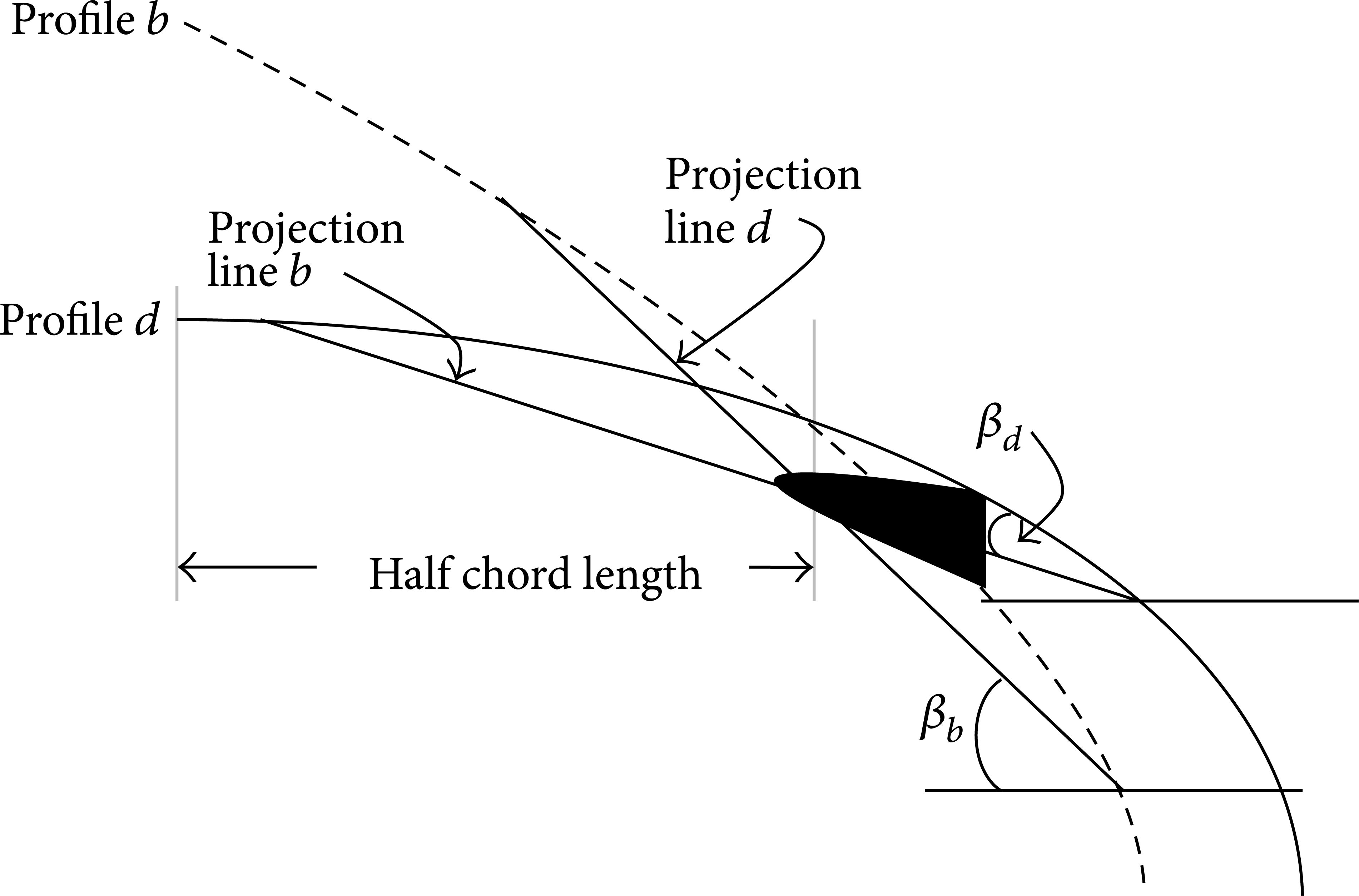
The twist angle deviation measurement.
5. Results and Discussion
In this study, two parameters, namely, the punch diameter and the depth of the embossing, were studied, and their effect on the quality of the hole was evaluated. Figures 12(a) to 12(c) present the measured roundness errors of the hole on the obtained profile at different diameters. For validation, measurement using Mitutoyo roundtest machine was performed, and the results agreed with those obtained with the presented method. Specimens with a diameter of 10 mm cannot be measured because of hole instability. From the experiment, the maximum roundness error is 13 µm. The results indicate that although the amount of error is different, both measurement techniques depict a similar pattern. The line without a marker is the profile measured with Alicona and the line with a marker is the profile measured with the roundtest machine.

Roundness error pattern at different hole diameters (a) 3 mm, (b) 5 mm, and (c) 10 mm.
In this study, the profile of the punch is considered to be the targeted profile, whereas the profile of the blade is taken as the manufactured profile. To ensure better visualization, white acrylic spray was applied to the surface of the die and the punch. For benchmarking, the twist angle of the blade from the theoretical and nominal models was mapped, as shown in Figure 9, and a very good agreement was obtained.
Figure 13(a) shows the profile constructed by using the profile of the blade section obtained from Alicona after the filtering and cleaning processes. Figure 13(b) illustrates the profile obtained after the mirroring technique was applied. The measured twist springback is summarized in Table 1. The twist angle was measured based on the edge of the profile by referring to the chord length of each section.
Twist springback measured.


The resulted profiles of the blade and punch (a) before and (b) after applying the algorithm.
Based on the result obtained from the measurement, the effect of the deformation ratio is considered to be significant, as depicted in Figure 11. As the deformation ratio increases, the springback also increases, especially at a deformation ratio of 3. However, beyond this deformation ratio, the increments gradually decline because twisting goes beyond the plastic region of the section.
6. Conclusion
This study aimed to evaluate the quality of a cold embossed hole. The evaluation is based on profile deviation gathered from 3D surface measurement. Overall, the produced hole is within acceptable limits. The quantified error agrees with the experimental value. The study also aimed to present a case study of the roundness error of the hole produced by cold embossing process of the pin head. The hole is embossed to produce a hole that is designed to ensure proper mating between the blade and the propeller's body. The results show that the roundness of the hole is within the control limit. The measurements were based on the difference between the profile obtained from the Alicona system, and CMM was used to validate the result. The error was measured based on a selected section of the propeller blade, which was assumed to represent the overall profile of the blade. The primary contributions of this paper found that optical images can provide a clear profile of the blade, which can be used to evaluate the geometrical defect of complex shape parts.
Comparisons were made between the resulted profiles and the established methods. For the case of roundness, comparison was made with the measurement of roundness error using Mitutoyo roundtest machine and the result depicted a deviation of less 5%, whereas in the case of twist springback measurement, a coordinate measurement machine (CMM) was utilized and the deviation is less than 10%.
Conflict of Interests
The authors declare that there is no conflict of interests regarding the publication of this paper.
Footnotes
Acknowledgment
The authors want to acknowledge Universiti Sains Malaysia for their sponsorship through Short Term Grant (AC 60312014).