
Abstract
Integrated casting and forging process (ICFP) is a new manufacturing method combining the advantages of both casting and forging. Aluminum structure parts, such as aluminum alloy automobile wheel, with complex shape and excellent mechanical properties can be produced by this process. The effects of different process parameters on the ICFP of the automobile wheel were simulated by Forge software. Microstructure of forging region and the nonforging region were studied by experiment. The results show that die temperature, static pressure of the injection piston, forging speed, and material flow have significant influences on the process. Compared with nonforging region, the microstructure of forging region becomes finer, more uniform, and denser. Meanwhile, the casting defects can be removed and mechanical properties improved.
1. Introduction
The application of aluminum alloy automobile wheels continues to grow because of the need of weight reduction and its benefit over the traditional stamped and welded wheels. As a result, most of the cars are now equipped with aluminum automobile wheels. Some manufacturing technologies including casting and forging process have been developed to produce aluminum alloy wheels. Much research has been carried out on the casting process of the automobile wheel. Zhang et al. [1] developed a mathematical model of the low-pressure die-casting process for the production of A356 aluminum alloy wheels to predict the evolution of temperature within the wheel and die. Wang et al. [2] analyzed defects of the electric motorcar aluminum wheels by gravity casting, and they found that the junction of the spokes and the rim, the hub is easy to produce casting defects. Maijer et al. [3] studied the effects of microstructure and defects on the impact properties of automotive wheels by low-pressure die-casting and predicted the final microstructure and shrinkage formation by analyzing the filling and solidification behavior of the aluminum alloy wheels. Chen and Li [4] investigated mechanical properties of aluminum alloy wheels produced by squeeze casting and found that wheels had high density, strength, and hardness. Forging process is also an important forming technology of aluminum alloy wheels. Compared to casting, the forged parts are characterized by fine-grained microstructure and excellent mechanical properties. Kim et al. [5] studied plastic deformation and heat transfer of 6061 aluminum alloy wheel and found that material flow, pressure distributions, temperature distributions, and forging loads can be used as basic data for process design and selection of equipment. However, many studies show that casting or forging process cannot meet the application requirements of complex shaped parts with high mechanical properties [6, 7]. Casting/forging process combines the advantages of casting and forging. First, casting is carried out in the casting die to attain a satisfactory preform for forging. Then, forging is carried out in the forging die to obtain the final product by using the cast preform. Kim et al. [8] and Wang et al. [9] found that casting/forging process was desirable for structure parts, which required good mechanical properties, complicated shapes, high geometrical precision, and surface quality.
Integrated casting and forging process (ICFP) was put forward to fabricate complicated parts with high quality. ICFP has the advantages of casting/forging process; besides it is more cost-effective, more energy-efficient, and requires fewer steps. ICFP integrates casting and forging procedure as a synergistic process in the one set of dies, which makes full use of the latent heat of solidification in forging. Besides, optimal configurations of ICFP are determined by the conventional trial-and-error method, which needs a lot of workload and is inefficient. Simultaneously, measurements of temperature and pressure distribution are very difficult in the real process. Finite element method (FEM) is one effective measure to solve these problems. In this study, FEM was used to simulate the fundamental of the ICFP and investigate effects of parameters.
2. ICFP Principle
Process principle of ICFP is shown in Figure 1. The process mainly includes four procedures: casting, solidification under pressure, forging, and opening die. ICFP integrates the casting and forging procedure as a synergistic process using one set of dies, which will significantly shorten the procedures of fabrication of parts. The specified region of part is forged, where excellent mechanical properties are required. Casting procedure ensures that the die cavity is fully filled. Static pressure of the injection piston holds several seconds before complete solidification. Pressure holding time is a period from the casting temperature of metal to that of metal temperature arriving at initial forging temperature. The pressure holding time is defined as forging waiting time. The purpose of static pressure in the ICFP is to complete the feeding. If the pressure is removed before forging, the shrinkage cannot be compensated and some shrinkage defects will occur in the part. However, the thermal center is located at the thickest region of part. Porosity and cavity are likely to appear in this region. That is because the solidified alloy at the other regions cannot move to the thermal center. Then forging procedure makes full use of the latent heat of solidification to further compensate the porosity and cavity of part. It is the key procedure of the ICFP. The density of casting aluminum alloy automobile wheel at the forging region is improved, because the forging force promotes the molten metal flow toward solidification shrinkage area. Consequently, the mechanical properties of the forging region can be improved under reasonable process parameters.

Process principle of ICFP.
A typical automobile wheel component was used as research object. Three-dimensional model of automobile wheel and the forging region are shown in Figure 2. Hub, spokes, and main load-bearing region are set to the forging region. The height of the wheel is 151 mm, and the maximum diameter is 431.8 mm (17 inches). The thickest section is 50 mm and the thinnest section is 5.5 mm.
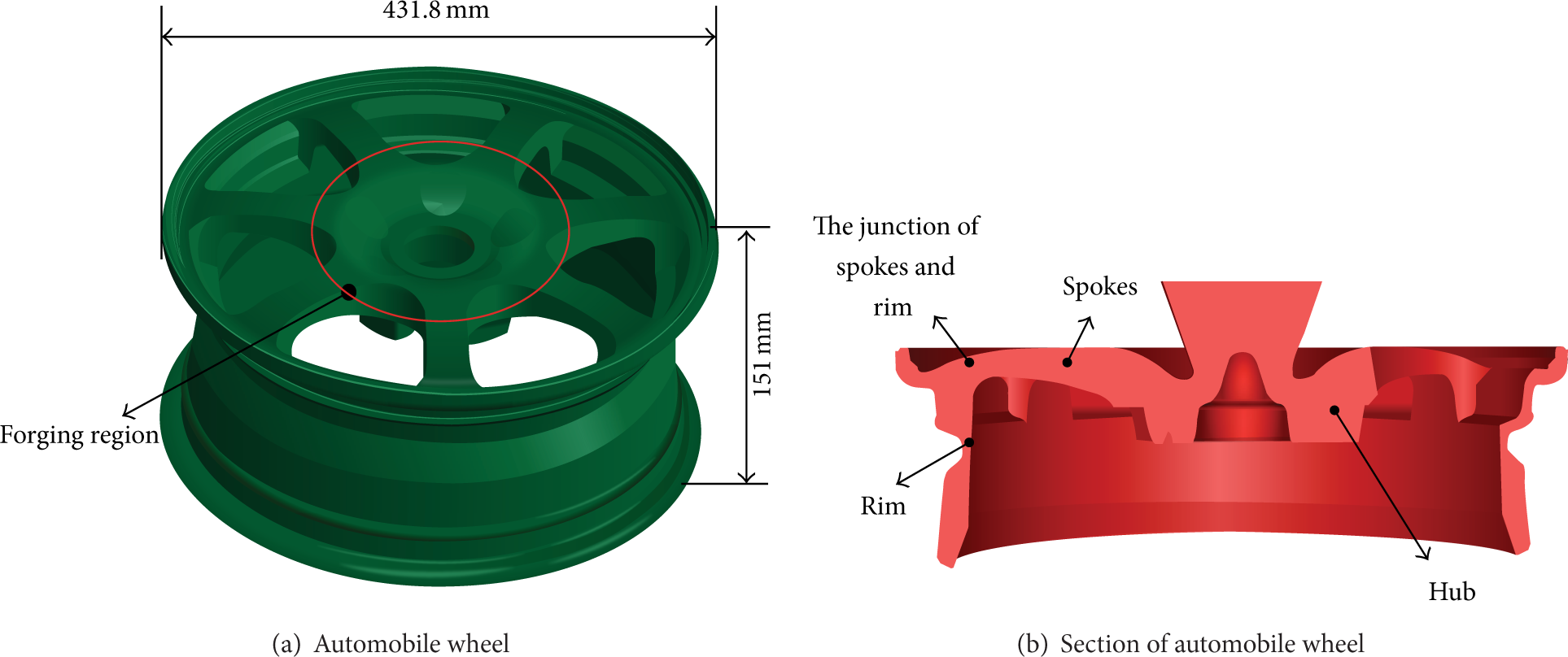
Three-dimensional model of automobile wheel.
Figure 3 shows three-dimensional model of composite die of ICFP for automobile wheel. Punch 1, top die 2, side die 3, 4, 7, 8, bottom die 5, and floating die 6 built a closed chamber during forming process. The bottom of the floating die 6 endures a presupporting force. The workflow of the die set is outlined below.
Casting: molten metal enters the cavity through the discharge and feed gate 10 under the pushing force of the injection piston 11.
Solidification: the aluminum alloy is gradually solidified under certain conditions and static pressure of the injection piston.
Forging: the punch 1 is moved down to forge the parts after a certain forging waiting time. If the force of punch 1 is larger than the presupporting force of the floating die 6, the floating die 6 goes down with the punch 1 and the wheel is forged. Surplus materials are discharged from the discharge and feed gate 10.
Opening die: the punch 1 moves back in the position after forging procedure; the bottom die 5 and floating die 6 go down; the side die completes the side core-pulling through a side core-pulling structure. Then the punch 1 and the pin-lift pattern stripping arrangement withdraw, and the wheel is ejected and removed from the die cavity.

Die set of automobile wheel.
3. Simulation
3.1. Finite Element Model
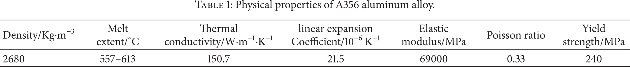
Numerical analysis of the ICFP was conducted using the Forge 3D software [10–12], based on the FEM. Geometric model of the forming process is presented in Figure 3. Thermomechanical calculations of this forming process were conducted on the assumption that the automobile wheel (see in Figure 2) was divided into 494,228 tetrahedral solid elements. The die set was meshed as rigid part by using triangular shell elements, which included the punch with 45,636 elements, side die with 92,777 elements, the bottom die with 137,774 elements, floating die with 11,642 elements, injection piston with 23,433 elements, and the top die with 89,409 elements. It was also assumed that the automobile wheel was made from A356 aluminum alloy, whose physical properties are listed in Table 1. The stress-strain curves of this alloy were obtained by thermocompression experiments, as shown in Figure 4.
Physical properties of A356 aluminum alloy.

Stress-strain curves of A356 aluminum alloy.
Temperature has significant effects on the solidification process of molten metal. Therefore, the heat transfer phenomenon is calculated firstly. Convection occurs within the part, at the metal/die interface, and within the die. The corresponding equations [8] for the heat flux are
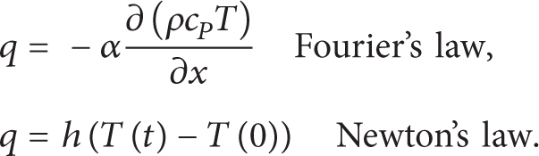
Here α is the thermal diffusivity, ρ is the density, c P is the specific heat capacity, and h is the heat transfer coefficient. Solidification of metal can be either steady state or nonsteady state process and involves phase transformation. Thus, it is a transient problem involving partial differential equations. Specific boundary conditions (BC) must be used to describe various casting processes. Classic BC used for computational modeling of casting solidification of ICFP can be expressed as follows:

The friction law based on shear stress criteria was used to analyze the friction condition between tools and metal. Frictional shear stress criterion considers that the maximum friction is a constant and should not exceed the pure shear stress of material
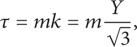
where τ is the frictional shear stress, m is the friction factor, and Y is the flow stress.
3.2. The Scheme of Simulation
Die temperature, static pressure of the injection piston, forging waiting time, forming force, and forging speed have important influences on the quality of parts in the integrated casting and forging process. Finite element models of ICFP were established and simulations were conducted to obtain the influence rules of process parameters on the forming process.
Schemes for simulation are listed in Table 2. In order to investigate the effects of the parameters, only one parameter is changed for each scheme. During simulation, the casting temperature of A356 is 700°C, the initial forging temperature of parts is 480°C, and the parts are cooled in the die. At the same time, it is assumed that the liquid metal fills the cavity instantaneously, and the forging amount is 3 mm.
Schemes for the simulation.

4. Results and Discussions
4.1. Die Temperature
Generally, the die temperature of die-casting filling is 150°C–300°C. Temperature field distributions of part under different die temperatures were analyzed. Forging waiting time and forming force were determined. The results show that the temperature of die has a significant effect on the distribution of temperature field, forging waiting time, and forming force.
4.1.1. The Influence of Die Temperature on Forging Waiting Time
Solidification of the wheel is inhomogeneous due to its large dimension and mechanical constraints. A pressure on molten metal during solidification can cause the reduction of shrinkage porosities and uniform microstructure, which can improve the mechanical properties [13]. In the solidification process, the temperature distributions of the wheel at the die temperature 300°C are shown in Figure 5. The cooling time increases in the thick region. Defects, such as shrinkage porosity and voids, are easily caused in the thick-sections of the part. So the forging waiting time has an important effect on the ICFP.
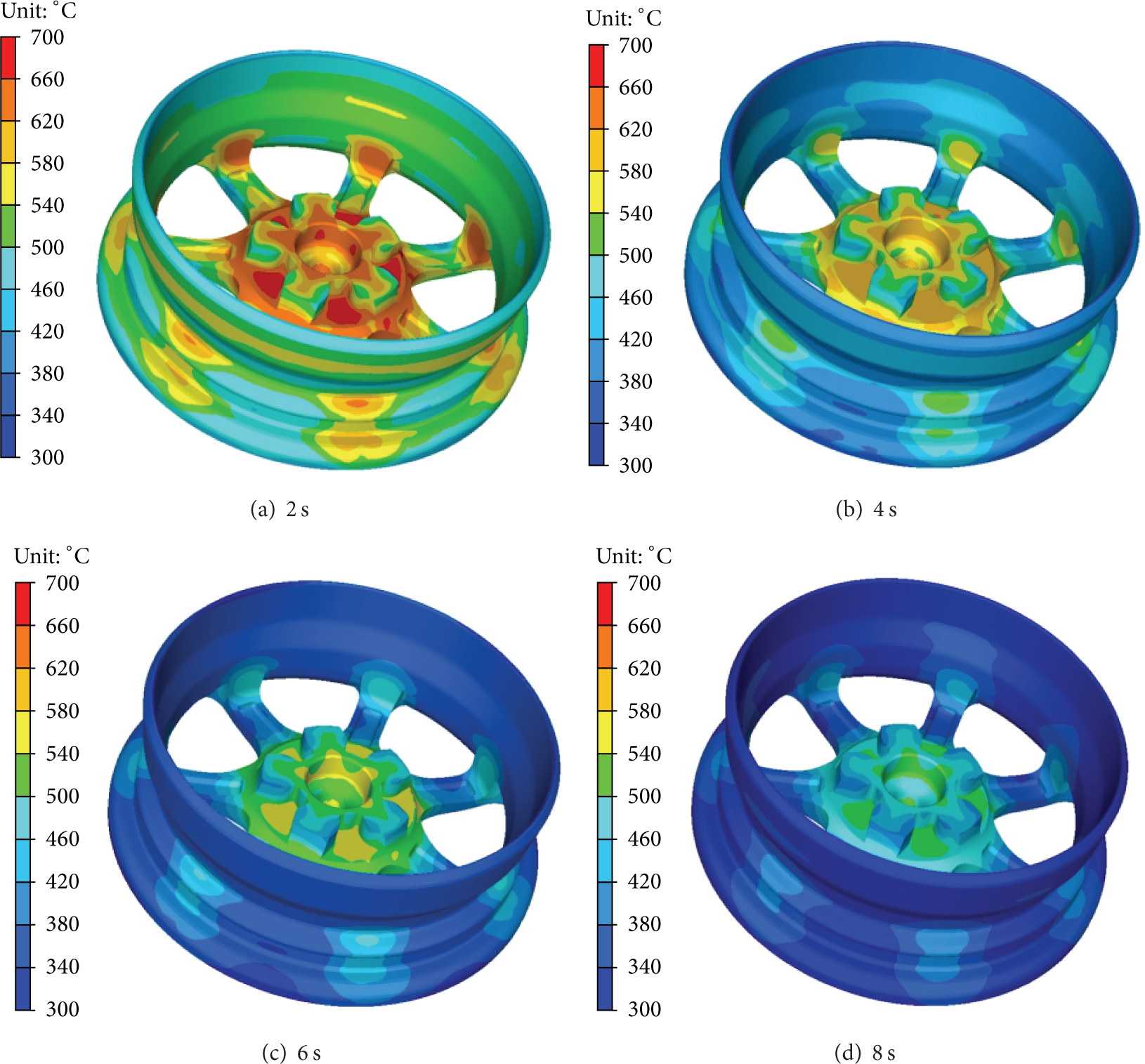
Temperature field with die temperature 300°C at typical time.
Cooling rules of the wheel at different die temperatures are shown in Figure 6. As can be seen clearly, with the increase of die temperature, the cooling time is longer. The forging waiting times are 8.6 s, 9.3 s, 9.5 s, and 10.5 s corresponding to the die temperatures at 150°C, 200°C, 250°C, and 300°C, respectively. The relationship of the forging waiting time with the die temperature is shown in Figure 7. It can be seen that forging waiting time increases with the increase of die temperature but not by much.

Hub temperature versus time curve.
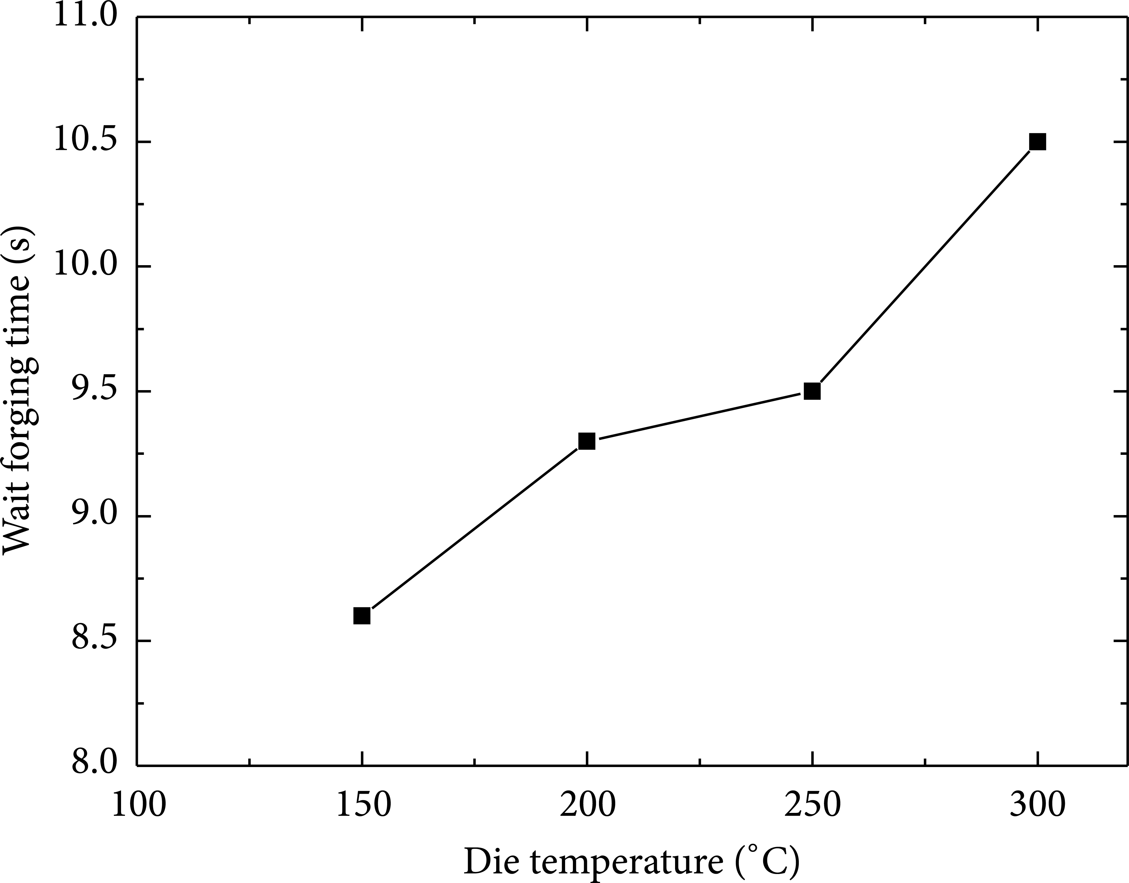
Forging waiting time versus die temperature curve.
4.1.2. The Influence of Die Temperature on the Forming Force
Four forming processes were simulated under different die temperatures and different forging waiting times, while the other process parameters are the same (see Scheme 1 in Table 2). Forging waiting time is selected according to Figure 7. The relationship between the forming force and time is obtained, as shown in Figure 8. The forming force is 28000 KN when the die temperature is 150°C. The forming force is 15000 KN when the die temperature is 300°C. The results illustrate that with the rising die temperature, the forming force decreases.

Forming force versus time curve.
4.2. Static Pressure
In ICFP, the static pressure can help the metal fill the solidification shrinkage and dense region of part. This is one of the reasons for the mechanical properties improvement. During solidification process and forging process, the aluminum alloy has to be pressurized and held for a certain forging waiting time. Four forming processes (see Scheme 2 in Table 2) are simulated with static pressures of the injection piston of 50 MPa, 100 MPa, 150 MPa, and 200 MPa, while other process parameters are the same. Forging effect is strongly dependent on the distribution of pressure field of parts. According to the study, high pressure leads to a dense microstructure [14]. Figure 9 presents the distributions of pressure field under different static pressures of the injection piston. The pressure of hub, spokes, the junction of spokes and rim, and rim decrease in sequence. The result demonstrates that the pressure of forging region is higher than that of nonforging region. The mechanical properties of parts will be improved under the function of static pressure of the injection piston.

The pressure field at different static pressures of injection piston.
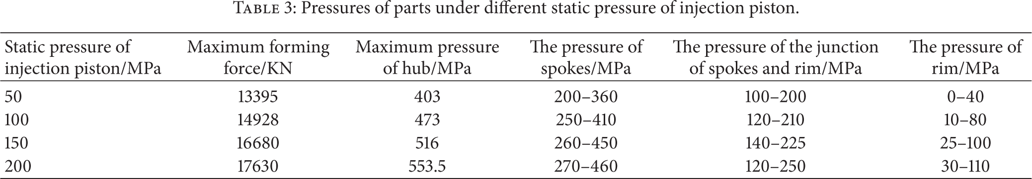
Pressures of part under different static pressures of the injection piston are shown in Table 3. The maximum forming force and pressure of parts decrease with the decreasing in the static pressure of the injection piston. The surplus material of forming process is pushed out of the discharge and feed gate by moving down the injection piston. Density of the part improved significantly with increasing of static pressure of the injection piston. Good geometrical precision and high surface quality will be obtained. However, if the static pressure of the injection piston exceeds 150 MPa, the surplus material may be pushed out from the contact surface of the top die and the bottom die. And also the large internal pressure may deform/damage the die, which shortens die life due to severe mechanical stresses. Therefore, the value of static pressure of injection piston should not be too big, and 100 MPa–150 MPa is suitable.
Pressures of parts under different static pressure of injection piston.
4.3. Forging Speed
Four forming processes (see Scheme 3 in Table 2) at 0.05 mm/s, 0.1 mm/s, 0.15 mm/s, and 0.2 mm/s were simulated, while other conditions are the same. The relationship between forming force and time is shown in Figure 10. Obviously, the forming force increases with the forging speed. It is because a smaller forging speed results in a smaller strain (see Figure 14). Since effects of the part temperatures at four forging speeds are similar, forging speed rather than forging temperature has an important effect on the forming force. However, low forging speed reduces the efficiency of the process. Therefore, the suitable forming speed range is from 0.1 mm/s to 0.15 mm/s.

Forming force versus time curve under different forging speeds.
4.4. Metal Flow of the Forging Process
Forging process of the wheel is realized through metal deformation in the die set. The complex metal flow induces large forging load, and stronger feeding ability of the metal, as well as dense microstructure [15, 16]. The metal flow during forging process in the ICFP is shown in Figure 11. There are mainly two flow directions: flow toward the discharge and feed gate, and flow from the spokes to the rim symmetrical to the wheel center axis. The metal at the base is pushed to flow from the junction of spokes and rim to the rim and then spreads to the surroundings and flows toward the junction of movable die and top die. There are two reasons for this metal flow pattern. First, during closed die forging process, the surplus material is pushed out from the inlet by the piston. Second, some metal will leak from the junction of the dies and result in defect.

Material flow of the forging process.
5. Experiment of ICFP
5.1. Experiment of ICFP
The SCV-2000 vertical squeeze casting machine was used to fabricate the A356 automobile wheel by the ICFP, as shown in Figure 12. Technical parameters of SCV-2000 vertical squeeze casting machine are shown in Table 4. Figure 13 shows the die for ICFP. The filling approach is die-casting. The experimental conditions are as follows: the casting temperature of the A356 aluminum alloy is 700°C, the temperature of die is 300°C, the amount of forging is 3 mm, the forging speed is 0.12 mm/s, the static pressure of the injection piston is 100 MPa, and the forging waiting time is 10.5 s. The hub is set to be forging region. This means that the hub and spokes are the forging region and rim, and the injection of spokes and rim are the die-casting region.
Technical parameters of SCV-2000 vertical squeeze casting machine.


SCV-2000 Vertical squeeze casting machine.

Die set for ICFP.

The comparison between simulation and experiment.
The mechanical properties, including tensile strength and elongation, were evaluated using cylindrical tensile specimens machined from the hub, spokes, and rim of the final product. The gauge length of the specimens was 25 mm and the gauge diameter 5 mm. All tests were carried out on the Instron testing machine at room temperature. The loading rate of each test was 2 mm/min.
5.2. Verification of FEA Model
The comparison between the experimental result and the simulation was conducted to verify the credibility of the simulation. As shown in Figures 14(a) and 14(b), the FEA model is established based on the real wheel and the formed wheel is obtained by ICFP. The shape and dimension of the simulation result is in agreement with the experimental one.
5.3. Mechanical Properties and Microstructure
Table 5 shows the relationship between position of wheel and mechanical properties from the tensile test. Both tensile strength and elongation increase with rim, spokes, and hub in sequence. This indicates that when the die-casting structure was deformed, the forging structure becomes more intense and fine porosity and other defects were eliminated. Ultimate tensile strength was increased from 239.46 to 290.65 MPa and the enhancing extent was 21%. Elongation was increased from 13.6 to 28.2% and the enhancing extent was 107%. The forging region of the automobile wheel has excellent mechanical properties equivalent to the conventionally forged product. Besides, experimental results and simulation results show excellent agreement, which verifies the validity of the simulation method.
Mechanical properties of produced automobile wheel by ICFP.

Microstructure of forging region and the nonforging region in the ICFP were analyzed. Metallographic samples were selected from the injection of spokes and rim, the hub, and spokes, as shown in Figure 15(a). The mechanical properties of the formed product are strongly dependent on the final microstructure [17–20]. Developed dendritic structures of α-Al particles will result in poor mechanical properties. The smaller the sizes of Al-Si eutectic are, the better the mechanical properties are. Figure 15 shows the microstructures of the A356 automobile wheel. The microstructure consists of α-Al particles and Al-Si eutectic matrix. Inhomogeneous distribution of the dendrite structures with large size (see Figure 15(b)) can be seen at the junction of spokes and rim. Metal at the junction of spokes and rim forges under lower pressure, which is similar to casting microstructure. Porosity is 0.52%. At the spokes (see Figure 15(c)), the dendrites have been broken into the rosette structure and short dendrite. Porosity is 0.22%. Dendrite structures of the hub (see Figure 15(d)) disappear gradually, and a large amount of spheroidal structures appears with decreasing grain size at the hub. Porosity is 0.30%. Metal at the spokes and hub endures higher pressure and larger deformation. Sizes of α-Al particles in Figures 15(c) and 15(d) are small and nondendritic structure is formed, so the mechanical properties of spokes and hub are better. However, the thermal center is at the hub which is the thickest. The dimension of the α-aluminum particles is larger than the region of spokes and the junction of spokes and rim. It is also clear that static pressure has significantly influenced the microstructure of the wheel. With increasing static pressure (see Table 3), the decrease in the number of dendrites and porosities, and refinement in the grain size and shape. The experimental results are consistent with the simulated results. That means the simulation method is reliable. The results show that ICFP can improve the microstructure and mechanical properties of aluminum alloy automobile wheel.

Photos of final product and microstructure of final product.
6. Conclusions
In this study, ICFP was proposed to produce aluminum automobile wheel, in which the die-casting and forging are combined in the same process. The static pressure refines the microstructure and removes the defects of forging region. According to the experimental and simulation results, the following conclusions are obtained.
The ICFP with different parameters was simulated by software Forge. The results show that forging waiting time increases with the increase of die temperature, and forming force decreases when die temperature rises. Pressure of forging region is higher than that of nonforging region, and the maximum forming force and pressure of parts increase when the static pressure of the injection piston and forging speed increase. The forming force increases with the forging speed. The suitable process parameters are as follows: static pressure of the injection piston is 100 MPa–150 MPa, forging speed is 0.1 mm/s–0.15 mm/s, and die temperature is 150°C–300°C. Material flows, die temperature, static pressure of injection piston, and forging speed have important effects on the quality of part.
The experimental results show that automobile wheel with complex shape and high mechanical properties can be produced by ICFP. Microstructure of forging region is finer, more uniform, and denser than that of nonforging region. Compared with die-casting, the mechanical properties of the automobile wheel produced by ICFP were greatly improved.
Conflict of Interests
The authors declare that there is no conflict of interests regarding the publication of this paper.