
Abstract
The aim of this paper is to design two improved baffles to solve the injection problem caused by traditional baffle in compact test separatorand use FLUENT software to study their effects on separator pressure loss and separation efficiency. The result shows: that anti-injection baffle can make compact test separator with a high separation efficiency with a relatively low pressure loss. Also, the diameter of anti-injection plate which makes the compact test separator at its highest separation efficiency is slightly smaller than that which makes the lowest pressure loss.
1. Introduction
The first patent on conical cyclone separator was obtained by O. Morse; since then, cyclone separation technology got unprecedented development [1]. In surface facilities of oil field, especially in the offshore oil field [2, 3], compact test separator is designed to remove liquid impurity in continuous gas phase. It can effectively remove droplets from gas in small space under very high pressure, thus it is given extensive attention. Sun et al. used CFD software FLUENT to study flow field, gas-liquid two-phase flow, and influence of structure parameters on separation performance of recycling cyclone separator which has similar structure to that of compact test separator. Their simulation data have good agreement with experimental data [4–6]. In recent years, with the progress of numerical simulation of cyclone separator, the simulation accuracy is improved from aspects of turbulence model, grid scheme, discrete format of control equations, and calculation steps [7]. The author uses numerical simulation method to study compact test separator. To solve the problem of injection caused by traditional baffle which reduces separation efficiency, the author puts forward two kinds of improved baffles and further explores their effects on separation efficiency.
2. The Structure and Working Principle of Compact Test Separator
The structure of compact test separator is shown in Figure 1. The gas-liquid two phases enter the separator by tangential inlet which can create a high-speed swirl in the main separation chamber. The strong centrifugal force makes droplets in gas phase go to the side wall of the main separation chamber. Liquid on the side wall freely flows to the storage chamber which is under the lower part of the main separation chamber. This is the first stage separation. After the first stage separation, the mixture in outer vortex comes into inner vortex from the space between kick-off cover and baffle and then goes upward through gas riser. Smaller droplets are forced to side wall of gas riser and form a liquid film. The liquid film enters the secondary separation chamber by the gap on the upper side of gas riser and then flows to the lower part of the main separation chamber through recycling pipe, thus completing the secondary stage separation.
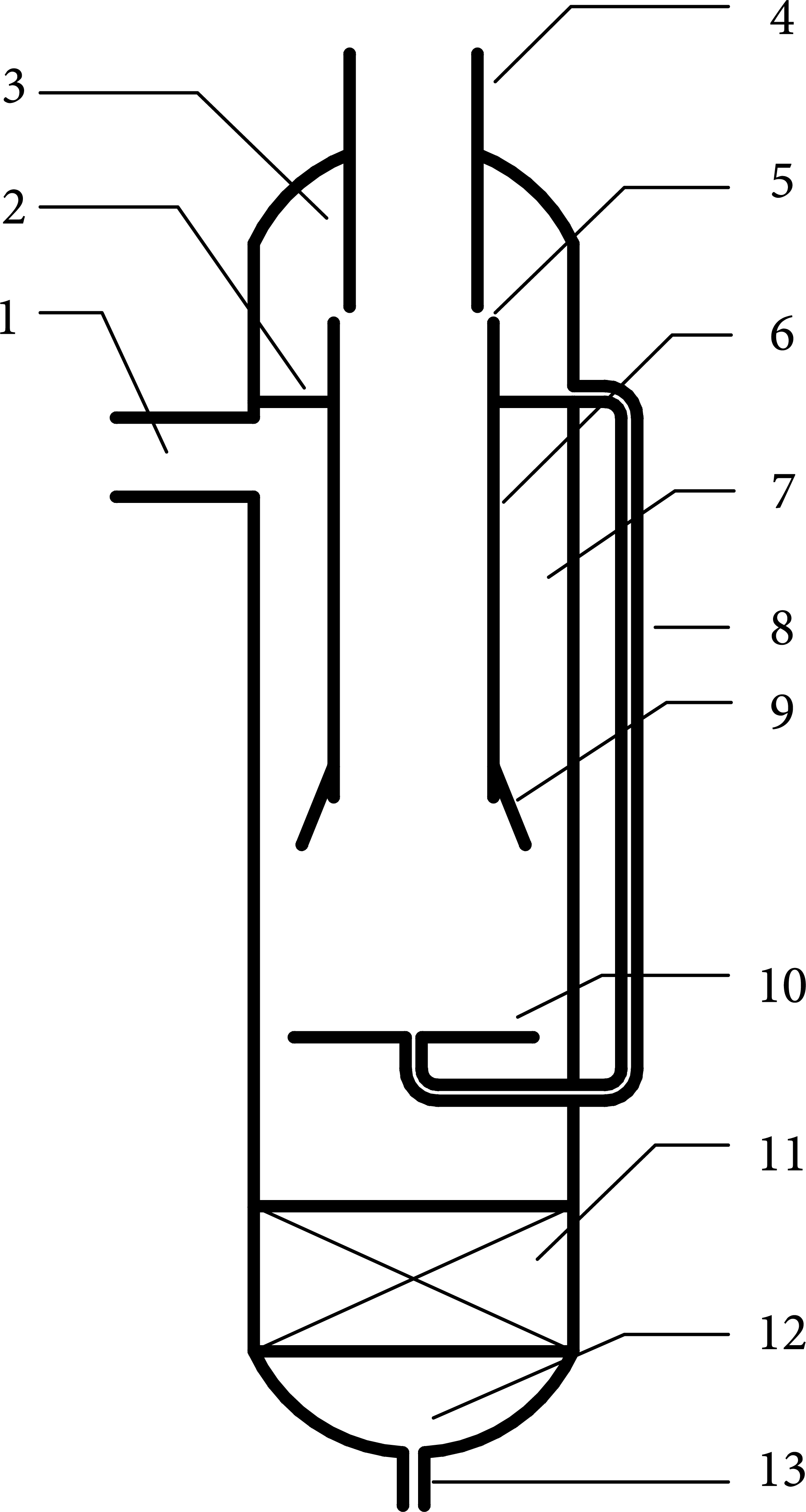
The structure of compact test separator. 1: inlet; 2: roof plate; 3: secondary separation chamber; 4: gas outlet; 5: gap; 6: gas riser; 7: main separation chamber; 8: recycling pipe; 9: kick-off cover; 10: baffle; 11: antivortex; 12: storage chamber; and 13: liquid outlet.
3. Numerical Simulation Method
Gas phase numerical simulation method in this study includes the following: choosing Reynolds stress model as turbulence model, using the uniform size unstructured hexahedral grid for grid scheme, choosing second-order windward format as discrete format of control equations, and choosing PRESTO! as pressure interpolation format. Select discrete phase model which couples two phases for the simulation of gas-liquid two-phase separation. Meanwhile, use the particle trajectory model to consider the random effect of the turbulent flow of continuous phase on the discrete phase. Figure 2 shows the grid of compact test separator model used in the simulation.
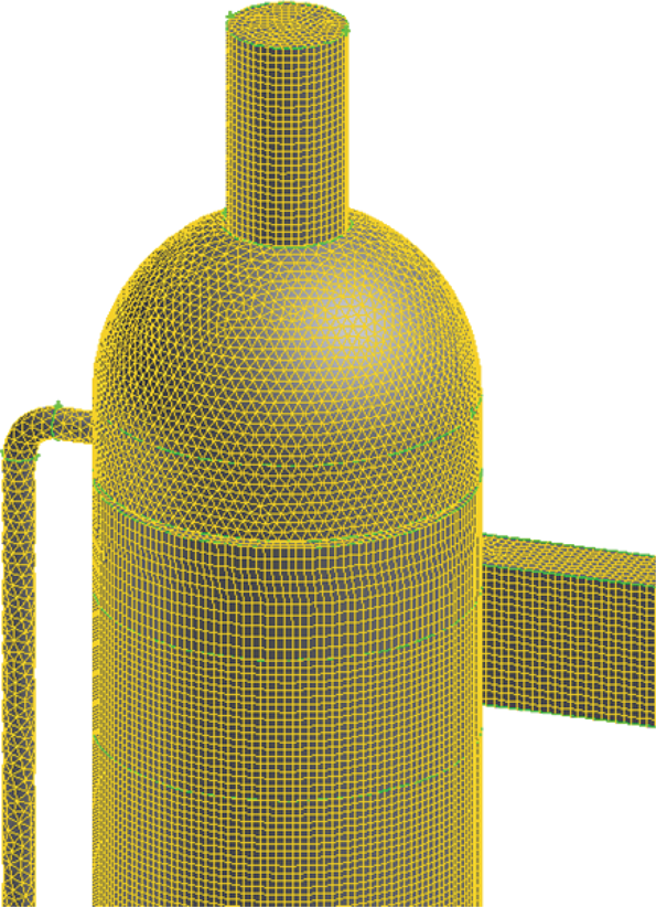
The grid of compact test separator model.
In this study, due to the smaller droplet diameter and lower liquid concentration, the fluid drag force of droplets is the main force. The force equilibrium equation of droplets in the x direction is
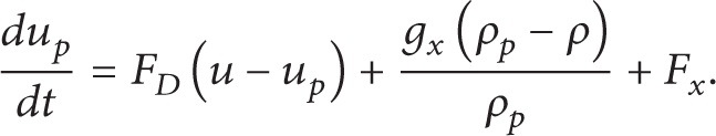
F D (u − u p ) is the drag force of droplet per unit mass, of which
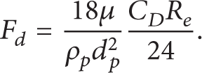
In the above equations, u is continuous phase velocity, u p is droplet velocity, μ is continuous phase dynamic viscosity, ρ is continuous phase density, ρ p is droplet density, d p is droplet diameter, and R e is relative Reynolds number.
Choose velocity inlet and pressure outlet boundary condition in numerical study. Use the standard wall function method to deal with the wall of separator.
4. The Baffle Structure
The baffle of compact test separator is mainly used to reduce the influence of vortex tail on separated liquid. It is found in the study that traditional flat baffle can easily create high axial velocity in the center of separator, causing injection phenomenon and decreasing the separation efficiency. The author puts forward conical baffle and anti-injection baffle to solve that problem. Figure 3 shows three kinds of baffle structures. The anti-injection plate is a circular plate installed above the anti-injection baffle.
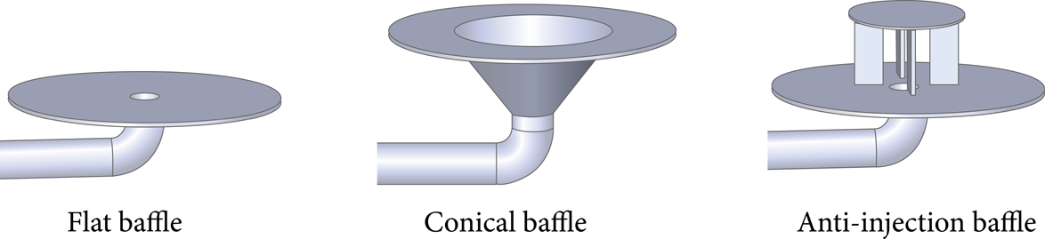
The structure of three kinds of baffles.
Figure 4 is tangential velocity curve of the cross-section between kick-off cover and baffle with three kinds of baffles. We can see that flat baffle makes the highest tangential velocity, anti-injection baffle takes second place, and conical baffle makes the lowest tangential velocity. So it is confirmed that anti-injection baffle and conical baffle can hardly create relatively high tangential velocity in the main separation chamber.
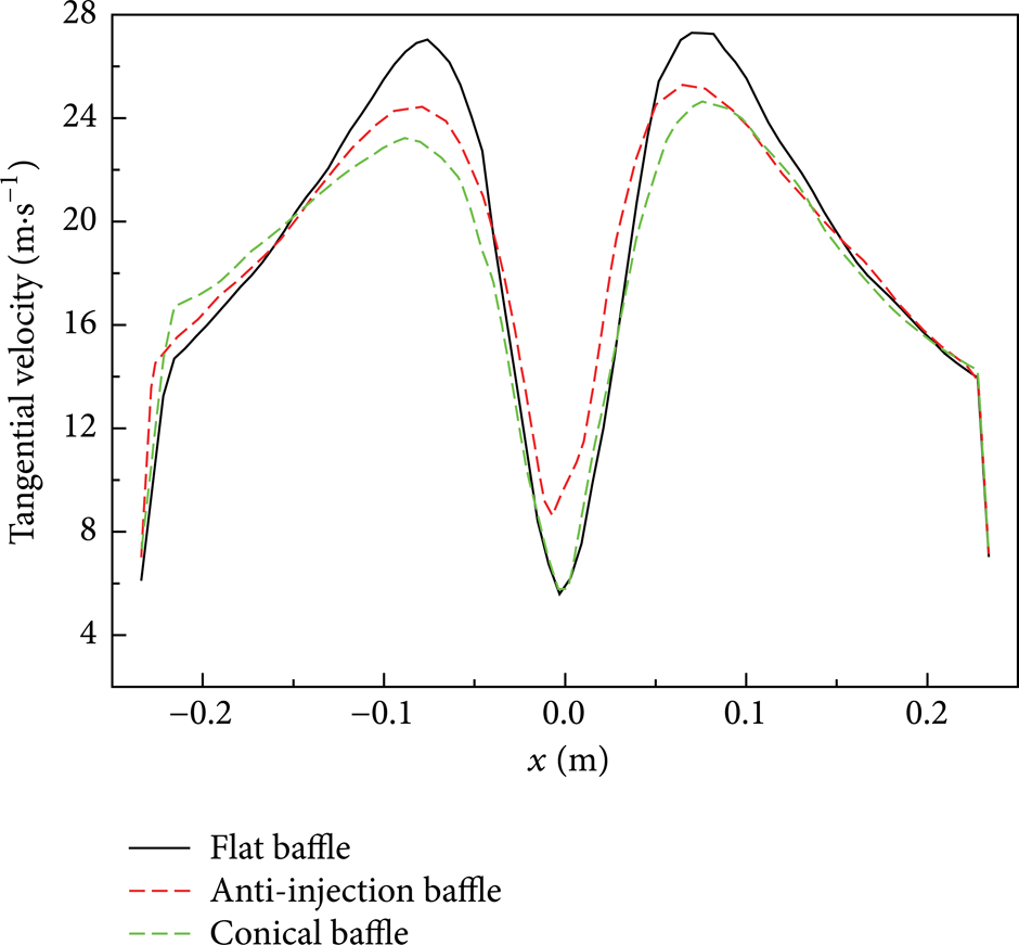
Tangential velocity curve.
Figure 5 is axial velocity curve of the cross-section between kick-off cover and baffle with three kinds of baffles. We can see that flat baffle makes the highest axial velocity in the center of the separator, conical baffle takes second place, and anti-injection baffle makes the lowest tangential velocity. Axial velocity curve can be explained by the structures of baffles. When flat baffle is installed, the recycling pipe outlet is located directly in low pressure area of vortex core and completely without shelter, so recycling fluid directly is injected into inner vortex and forms a high axial velocity in the center of separator. Conical baffle has a conical outlet for recycling pipe which can gradually enlarge the spout of recycling fluid, so axial velocity is lower. Anti-injection plate located on the anti-injection baffle not only can make the outlet of recycling pipe deviating from low pressure area of vortex core, as shown in Figure 6, but also can block the direct injection of fluid into inner vortex, thus it can make the lowest axial velocity in the center of separator.

Axial velocity curve.
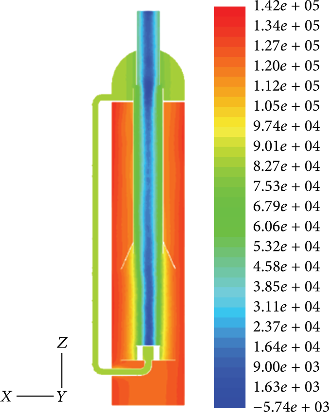
Static pressure contours.
The pressure loss of separator is defined as follows:

of which p i is inlet section average pressure and p o is outlet section average pressure.
Figure 7 is the pressure loss of separators with three kinds of baffles. We can see that flat baffle makes the highest pressure loss, anti-injection baffle makes lower pressure loss, and conical baffle makes slightly smaller pressure loss than that of anti-injection baffle. This can be explained by the curve of tangential velocity. Flat baffle can form the strongest vortex; the internal friction loss and turbulent viscosity stress energy loss are the largest, so it makes the highest pressure loss. Conical baffle makes the weakest vortex, and the pressure loss is the lowest.

Pressure loss.
Figure 9 is the grade separation efficiency curve of separators with three kinds of baffles. When droplet diameter is relatively small, anti-injection baffle makes the highest grade separation efficiency, conical baffle takes second place, and flat baffle makes the lowest one. With the increase of droplet diameter, grade separation efficiency of flat baffle rises fast and exceeds conical baffle. This is because, when the droplet diameter is relatively small, the highest axial velocity made by flat baffle makes the recycling fluid directly inject into inner vortex, causing low efficiency of the secondary stage separation for small droplets. With the increase of droplet diameter, the effect of tangential velocity on separation efficiency is more and more significant, so grade separation efficiency of flat baffle rises fast. Meanwhile, conical baffle cannot effectively separate medium diameter droplets due to low tangential velocity. Anti-injection baffle maintains the highest grade separation efficiency because it can effectively prevent injection phenomenon and create relatively high tangential velocity. Figure 8 is the total separation efficiency of separators with three kinds of baffles. We can see that because conical baffle cannot effectively separate medium diameter droplets, it makes the lowest total separation efficiency. The total separation efficiency of flat baffle is slightly higher than that of conical baffle. Anti-injection baffle maintains the highest total separation efficiency.

Separation efficiency.

Grade efficiency curve.
5. The Diameter of Anti-Injection Plate
Anti-injection plate is the most important structure of anti-injection baffle. It not only can make the outlet of recycling pipe deviating from low pressure area of vortex core but also can block the direct injection of fluid into vortex; thus it plays an important role to enhance separation efficiency of small diameter droplets. The diameter of anti-injection has relations with the degree of recycling pipe outlet deviating from the low pressure area of vortex core and the anti-injection ability; therefore it has important influence on the performance of compact test separator. Choose a separator model with an inner diameter of 480 mm as an example to study these relations.
Figure 10 is the axial static pressure curve in the center of recycling pipe with different anti-injection plate diameters. When anti-injection plate diameter is relatively small, static pressure in the recycling pipe decreases from top to bottom. The decreasing trend of static pressure becomes slower with the increase of anti-injection plate diameter. When anti-injection plate diameter is large enough, static pressure in the recycling pipe increases from top to bottom. The smaller the anti-injection plate diameter, the smaller the degree of recycling pipe outlet deviating from the low pressure area of vortex core and the lower the static pressure of the recycling pipe outlet. Figure 11 is the axial velocity curve of cross-section of recycling pipe with different anti-injection plate diameters. When anti-injection plate diameter is relatively small, the downward axial velocity in recycling pipe is relatively large because of its relatively high static pressure gradient in the direction of recycling. By increasing the diameter of anti-injection plate, static pressure gradient in the direction of recycling decreases and downward axial velocity decreases. When anti-injection plate diameter is large enough, static pressure gradient changes direction and axial velocity is reversed. The upward axial velocity in recycling pipe is completely against the working principle of compact test separator, which invalidates the secondary separation, so this situation absolutely needs to be avoided in this study.

Static pressure curve in recycling pipe.
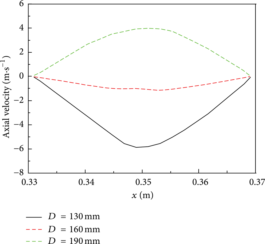
Axial velocity curve in recycling pipe.
Figure 12 is the pressure loss curve of separators with different anti-injection plate diameters. We can see that, with the increase of the injection plate diameter, the pressure loss firstly decreases and then increases and reaches the minimum when the diameter is 160 mm. As shown in Figure 10, when anti-injection plate diameter is 160 mm, static pressure gradient in the direction of recycling is relatively small. Theoretically, when static pressure gradient is zero in the recycling pipe, the recycling pipe does not act at all, and the pressure loss is the minimum, therefore, the anti-injection diameter which makes the minimum pressure loss should be slightly larger than 160 mm.

Pressure loss curve with different anti-injection plate diameters.
Figure 13 is the grade separation efficiency curve of separators with different anti-injection plate diameters. When injection plate diameter is large enough, the secondary separation cannot act because of the reverse flow in recycling pipe, so grade separation efficiency for small diameter droplets is particularly low. When anti-injection plate diameter is relatively small, the grade separation efficiency for small diameter droplets slightly decreases due to the decrease of anti-injection ability.

Grade efficiency curve with different anti-injection plate diameters.
Figure 14 is the total separation efficiency curve of separators with different anti-injection plate diameters. With the increase of the anti-injection plate diameter, total separation efficiency increases slowly and reaches the maximum at the diameter of near 160 mm. To further increase anti-injection plate diameter, total separation efficiency falls sharply due to the reverse flow of recycling pipe.

Total separation efficiency curve with different anti-injection plate diameters.
6. Conclusion
(1) Comparing to anti-injection baffle, conical baffle has slightly less pressure loss, but it has the lowest separation efficiency. Comparing to conical baffle, flat baffle has slightly higher separation efficiency, but it has the highest pressure loss. Anti-injection baffle can make the highest separation efficiency with a relatively low pressure loss, thus it is the best choice for the compact test separator.
(2) While the diameter of anti-injection plate is small, with the increase of its diameter, the reflux of recycling pipe decreases, the total separation efficiency increases, and the pressure loss decreases. Theoretically, when the axial velocity in recycling pipe is zero, the secondary stage separation will not happen and the total separation efficiency will be relatively low, which shows that the total separation efficiency has decreased at that diameter. Therefore, it is confirmed that the anti-injection plate diameter which makes the highest total separation efficiency is slightly smaller than the diameter which makes the lowest pressure loss.
Conflict of Interests
The authors declare that there is no conflict of interests regarding the publication of this paper.