
Abstract
In the process of hard rock breaking, the conical pick bears great cutting force and wear, and the cutting efficiency is lower. Thus different combination ways of water jet and conical pick were proposed to solve this issue; for instance, water jet placed in the front of pick (JFP) and water jet through the center of pick (JCP) was researched by numerical simulation and experiments in this paper. First, the models of rock breaking were built based on SPH combined with finite element method. Then, the stress distribution of rock and the cut force of pick were analyzed when the rock broken by the conical pick assisted with the high pressure water jet. It indicates that the effect of the JCP on rock breaking is better than the JFP. At last, experiments about rock breaking with a conical pick and the JCP were conducted to verify the reliability of the simulation. It indicates that the rock breaking with the assistance of high pressure water jet cannot only reduce the pick force, but also increase the rock crushing volume.
1. Introduction
Conical picks are the essential cutting tools used especially on road headers and continuous miners and shearers, whose cutting performance affects directly the efficiency and the cost of rock excavation. However, the cutting force and abrasion loss of picks are great in the process of hard rock breaking. To solve these problems, the scholars and engineers carried out a lot of research, which included three aspects: changing the material of a pick [1–4], modifying the structure parameters of a pick [5–7], and breaking hard rock assisted with high-pressure water jet [8, 9]. The effects of the first two methods on decreasing the cutting force and improving the cutting efficiency of a pick were not obvious, while the cutting force of a pick could be reduced by 30~50% with the third method.
Thus, the scholars have paid more attention to the hard rock breaking assisted with water jet. It was found that the forces on a free-rolling cutter were reduced by 40% using water jet at pressure in the range of 5~40 MPa, which represented a significant improvement in cutting performance [10]. Experiments on the performance of PDC cutters resisting different combined loads of static thrust, impact, cutting, and water jet on Missouri red granite and Halston limestone were investigated to verify the feasibility and efficiency of drilling assisted by water jet in hard rocks, which indicated that the combined mode of cutting impact was effective in hard rock [11]. The results were presented for the investigations conducted on test stand in cutting artificial samples of rock with the ultimate compressive strength up to 105 MPa with and without the high-pressure water jet supply [12]. The basalt and the sandstone, the pressure impulse, and the impact force of the water jet were measured by utilizing the experimental method to contrast the effect of the pulsed jet and the continuous jet on the granite [13]. The mechanisms involved in the rock-pick-water jet interaction were studied to evident the contribution of the jet both as a way to weak the rock and to increase the stress leading to crack formation [14]. To determine the effects of different operational parameters, such as traverse velocity, standoff distance, and pump pressure on performance parameters, namely, cutting depth and width, the experiments were conducted with pure water jet by using Italian granite sample [15].
With the development of computer technology, numerical simulation technology had been widely applied to the study on rock breaking process. The DIANA program of finite element method was adopted to simulate the rock breaking under extrusion of disc cutter and ball flat indenter [16]. The simulations were done by Franc2D software to analyze rock crack in the rock breaking process [17]. The effects of the high-pressure water jet with different impact speeds were measured by utilizing the numerical simulations method to study the propagation and attenuation of stress wave [18]. 2D and 3D discrete element models were established, respectively, to research the rock breaking process, and the results were compared with the experiment [19]. The experiment and numerical simulation were conducted with pure water jet to research into the central-body nozzle, and the core area and diffused area were discovered [20].
The above works provided reference for our research, which have paid more attention to the rock breaking by a pick assisted with water jet placed in the front of a pick (JFP), shown in Figure 1.
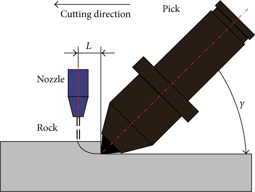
Rock breaking model of JFP.
If the arrangement of the pick and water jet was separate, there were several problems in actual application in the process of rock breaking by a pick assisted with water jet. On one hand, nozzle is damaged easily by rock fragments when nozzle is close to rock; On the other hand, the energy of water lost largely when nozzle is too far away from the rock. To avoid these problems, jet through the center of pick (JCP) was presented, which had been paid little attention, as shown in Figure 2.
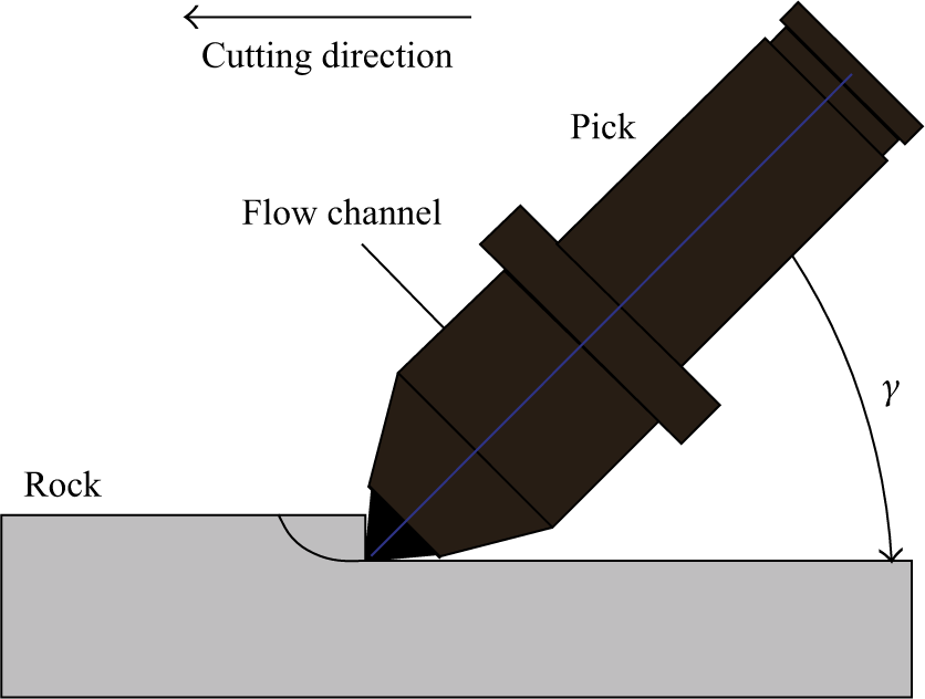
Rock breaking model of JCP.
However, the research on the rock breaking by a pick assisted with water jet was mostly conducted through experiments. Due to the poor transparency of the rock, the complex interactions among rock, pick, and water jet are difficult to obtain through experiments, and most attention were paid to the rock breaking by a pick assisted with water jet placed in the front of a pick (JFP). Moreover, there was little research on water jet through the center of a pick (JCP). Thus, in order to obtain the interactions mechanism among rock, pick, and water jet and to analyze the rock breaking performance of JCP and JFP, the method of SPH particles combined with finite element was proposed in this paper, and the rock breaking models of a pick assisted with water jet were built in two styles (JCP, JFP). Moreover, the numeric simulations and experiments were conducted. This research is aimed at improving the efficiency of rock breaking and providing a reference for the further researches on rock breaking by conical picks coupled with water jet.
2. Numerical Model
2.1. SPH Method
“Smoothed Particle Hydrodynamics (SPH)” is a new class of mesh-free methods, which has been developed to solve the large deformation problems efficiently by constructing the approximation completely on nodes instead of meshes. It was first applied to solve astrophysical problems and has been extensively applied in various fields, such as fluid dynamics, molecular dynamics, and solid mechanics. Because of its mesh-free features, the SPH can be applied to solve discontinuous problems through continuum mechanics. It was successful to demonstrate that the SPH was applicable for simulation of the fluid impact [21].
The theoretical basis of the SPH is the interpolation theory. By introducing an interpolation function (kernel function W) that gives the “kernel estimate” of the field variables at a point, the properties of each particle are evaluated by the integrals or the sums over the values of its neighboring particles. A problem domain Ω that is discretized by a group of particles as shown in Figure 3. Assuming has a compact supporting domain with a radius of kh, approximations of a function f(x) and its differential form 〈∇f(x)〉 at point i can be expressed by the discretized particles as [22]:

where the summation is over all the particles with a total number of N, including particle (i) within the supporting domain of the given particle i; the labels j are those influenced particles which are the neighboring particles of the particle i; m j is the mass of particle j; h is called the smoothing length which defines the supporting domain of the particle; W xi (x i − x j ,h) is the smoothing kernel function.

Kernel function.
In order to build the numerical models of the rock breaking by a pick assisted with water jet, the model of rock was established using finite element method; the model of the water jet was established using SPH method, in which the water jet was discretized into SPH particles. If the coordinate of particle α was x i at initial time, it would be x j at t time. Thus, the position of particle α was a function of the initial coordinate x i , namely, x j = x j (x i ,t). In hydromechanics, the following equations were often used to describe the motion and status of the fluid when the hydrodynamics problems were solved by SPH method [23–25].
Position equation of the particle is
Mass conservation equation of the particle is

Momentum conservation equation of the particle is

Energy conservation equation of the particle is

where ρ(x i ) is the density of particle i; m j is the mass of the particle j and the unit is kg; σ αβ is the stress tensor and the unit is Pa; v(x i ) is the velocity of particle i and the unit is m/s; E(x i ) is the internal energy per unit mass of particle i and the unit is J; Π is the artificial viscosity force and the unit is N; H is the artificial heat flux and the unit is J/s; W is the kernel function of the particle.
2.2. Failure Criterion of Rock
The rock breaking could be expressed by the rock failure criterion. In LS-DYNA, the nonlinear material DRUCKER_PRAGER [26] was used to imitate the rock, and the algebraic expression is
where J2 is invariant of the stress deviator and κ and β are the correlative coefficient.
The parameters κ and β in (6) could be acquired according to
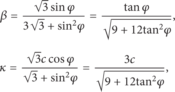
where c is the cohesive force and φ is the internal friction angle of rock.
In order to realize the failure criterion of rock, the parameters of rock were controlled by adding the Erosion Keyword “Mat_Add_Erosion” in LS-DYNA [27].
2.3. Finite Element Model
To verify the feasibility and efficiency of rock breaking by a pick assisted with water jet, the two styles (JFP and JCP) were all contrasted with the rock breaking model of a pick, and the simulation models were shown in Figure 4.

Simulation models of rock breaking.
2.4. Parameters of the Models
The parameters of the rock and the conical pick in the numerical models were shown in Table 1. And to contrast the efficiency of the two styles (JCP, JFP), the simulations were carried out under the conditions of different cutting depths (7 mm, 11 mm, 15 mm, and 19 mm).
Mechanical parameters of rock and pick.

The size of the rock was 600 × 400 × 300 mm, and the material of the pick was linear elastic. In order to ensure that the pick moved uniformly, the bottom of pick was dealt with as rigid for the reason that only a rigid body could be assigned a constant speed in LS-DYNA. The cutting speed of the pick was 2 m/min in the simulations.
The theoretical speed [28] of the high-pressure water jet is

As the pressure of water jet was 40 MPa, the speed was
In the simulations, the radius r of water jet was 1 mm, and advance speed v1 of water jet was 2 m/min. When the water jet was placed in the front of the pick, the distance L between the water jet and the pick tip was 2 mm, as shown in Figure 4(b).
In LS-DYNA code, the MAT-NULL which has no shear stiffness and the GRUNEISEN equation of state (EOS) for pressure response can be used to describe the behavior of water [21]; its density was 1000 kg/m3, the dynamic viscosity was 0.001 Pa·s, and the Poisson ratio was 0.5. And the EOS_GRUNEISEN is given by (10) to describe its pressure and volumetric strain relation:

where E is the internal energy of unit volume and the unit is J, C is the intercept of the curve μ s − μ p which is the relationship between wave velocity and particle velocity, S1, S2, and S3 are the slopes of the curve μ s − μ p , respectively, γ0 is the EOS_GRUNEISEN coefficient, and α is correction coefficient about the relationship between the EOS_GRUNEISEN coefficient and volume. The specific state equation parameters were shown in Table 2.
State equation parameters of water.

3. Result of Numerical Simulations
3.1. Comparisons of Rock Stress
In order to analyze the failure mechanism of rock under different conditions, the stress distribution of rock was used to describe the failure degree.
Rock compressive stress distribution under different conditions of cutaway view along the cutting direction is shown in Figure 5.
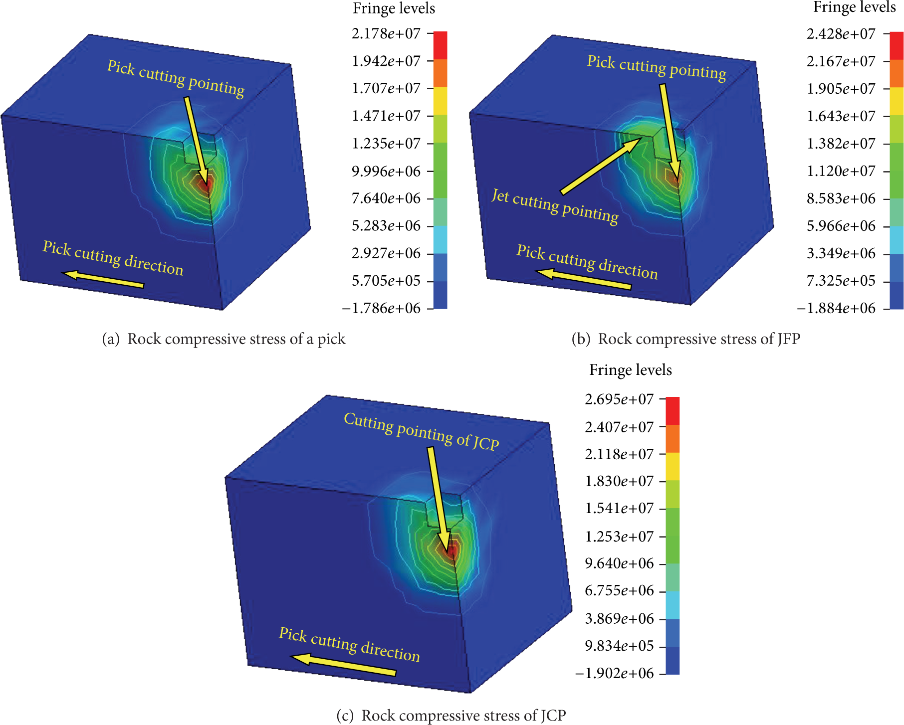
Comparisons of rock compressive stress.
Figure 5 shows that the maximum compressive stress of the action point is 21.78 MPa when the rock breaking by a pick. The maximum compressive stress under the JFP is 24.28 MPa, and the JCP is 26.95 MPa. It illustrates that the JCP can crush the rock easily and effectively. And the maximum tensile stress of the rock breaking by a pick is 1.786 MPa, the maximum tensile stress of JFP is 1.884 MPa, and the JCP is 1.902 MPa. For the rock is known as a brittle material, its tensile strength is much lower than the compressive strength, and tensile failure is much more apt to occur. Thus, the best rock breaking style is the JCP in theory.
Figure 5(b) shows that the compressive stress of the action point of JFP is larger than only a pick, but the compressive stress acted on the rock by both the water jet and the pick cannot be superimposed effectively. While in Figure 5(c), the rock is in compression at the initial moment, and the maximum compressive stress appears at the impact center. The compressive stress decreases gradually with the radial distance, and then the compressive stress converts into tensile stress, and the maximum tensile stress appears around the impacted point, which is corresponded with the experiment.
From what has been discussed above, comparing the JFP, the compressive stress value and tensile stress value of JCP are larger, rock is easier to be crushed, and tensile failure is much more apt to occur. Thus, rock fractured capacity of JCP is considered better.
3.2. Comparisons of Pick Force under Different Conditions
3.2.1. Comparison of the JFP and a Pick
The cutting force of the pick was used to reflect the efficiency of rock breaking. The smaller the cutting force of the pick was, the better the effect of water jet was. The simulation results of the JFP and a pick under different cutting depths (7 mm, 11 mm, 15 mm, and 19 mm) were shown in Figure 6 and Table 3.
Comparison of cutting force.

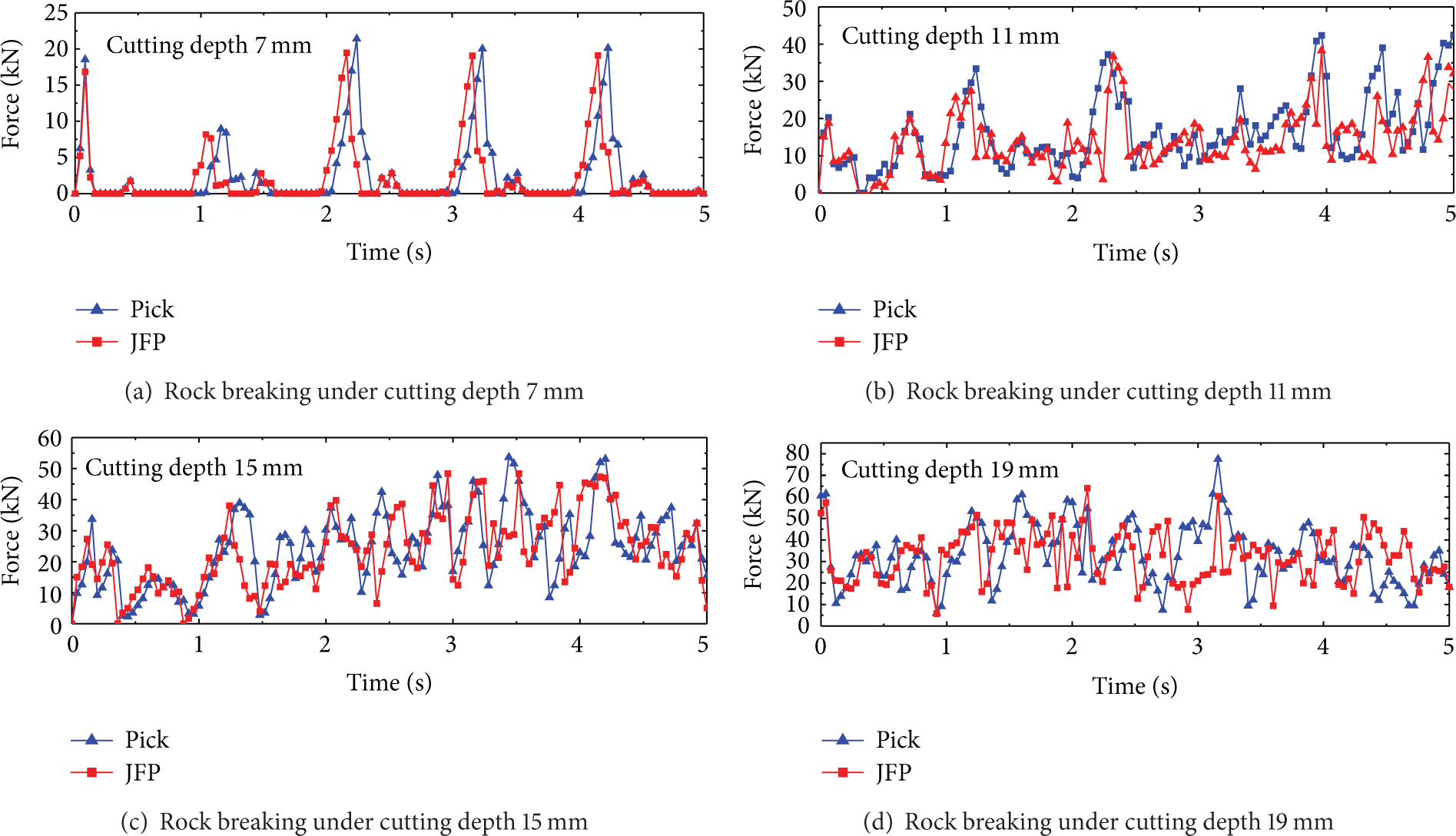
Comparison of cutting force of JFP and a pick.
Figure 6 and Table 3 show that the water jet placed in the front of the pick is effectively useful for rock breaking when the pressure of water jet is 40 MPa. Comparing with a pick, the maximum decrease rate of pick force of the JFP is 9.52% when the cutting depth is 7 mm. But the assisting effect of water jet on rock breaking decreases with the cutting depth.
The cutting force of a pick increases rapidly when the pick contacts the rock under the cutting depth 7 mm in Figure 6(a), and the maximum is 21.4 kN. The reason is that the elastic deformation happens on the rock surface at initial moment, and there will be crack produced along with the pick cutting into the rock, which results in the cutting force increase. Then, the cutting force will drop to the minimum until the crack expands to the next free surface and the rock will fracture at the same time. The cutting force increases with the cutting depth, and the force curve of the pick becomes more complicated, which results in the frequency of jump rock crushing increase, the abrasion of pick speedup, and the pick life decrease.
3.2.2. Comparison of the JCP and a Pick
The cutting forces of the JCP and the pick are shown in Figure 7 and Table 4.
Cutting force comparison.

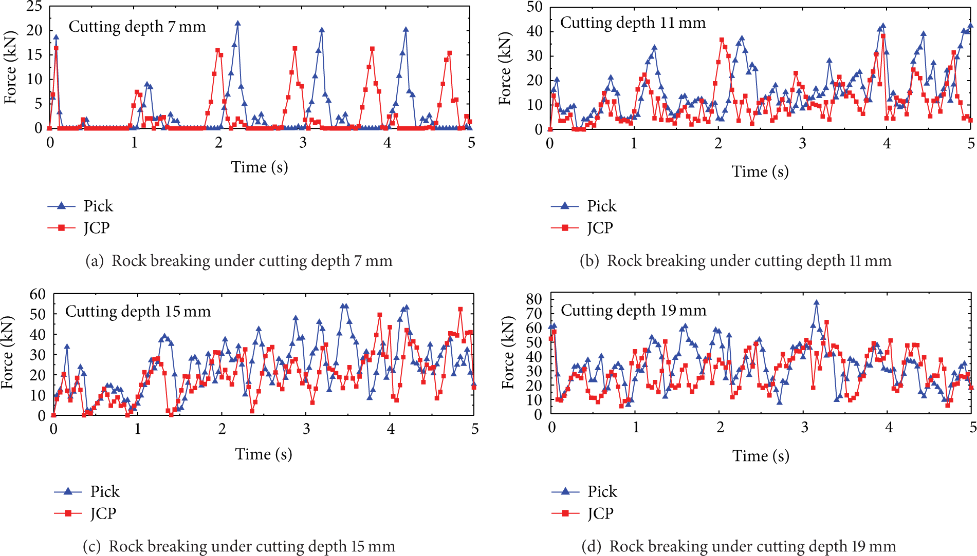
Comparison of cutting force of JCP and pick.
Comparing with a pick, the maximum cutting force of JCP reduces by 23.5%, as shown in Figure 7 and Table 4, and one jump rock crushing time under the JCP is smaller than a pick, which indicates that the efficiency of rock breaking is improved obviously with the assistance of water jet. The numerical results show that the minimum cutting force of each jump rock crushing under the JCP is lower than a pick. The JCP effectively reduces the cutter force when the cutting depth is 11 mm, 15 mm, and 19 mm.
Contrasting Table 3 with Table 4, the decrease rate of the cutting force of the JCP is 23.5%, 21.88%, 15.09%, and 11.44% with the cutting depth of 7 mm, 11 mm, 15 mm, and 19 mm, respectively, when the pressure of water jet is 40 MPa. On the same conditions, the reduction percentage of the cutting force of the JFP is 9.52%, 7.92%, 4.91%, and 3.14%. Thus, the JCP is more useful for rock breaking to the JFP.
The reasons are that the water jet impacts the rock cracks timely under the JCP, and the whole energy of water jet affects the rock cracks directly. However, a part of energy of the water jet is lost under the JFP, which is due to that the impact point of water jet is not the crack but the rock surface. And the pressure of water jet is smaller than the compressive strength of the rock, which results in the loss of energy and effect of rock breaking decreases.
4. Experiments of JCP
4.1. Experimental Principle
To verify the correctness and reliability of the numerical model of JCP, the experiments of rock breaking by the JCP were carried out. The rock and coal breaking testbed was shown in Figure 8, and the JCP was shown in Figure 9.

Rock and coal cutting testbed.

Structure of JCP.
Figure 7 shows that the rock sample is fixed on the testbed by the clamping cylinder. The slideway can reduce the friction between the rock sample and testbed and make the loading and unloading and moving of the rock sample easy. The pushing cylinder and pushing guide rails can realize the linear reciprocating cutting of the cutter. The cutting depth can be increased by putting steel sheets under the rock sample. The change of oil pressure in the pushing cylinder could be measured by the pressure transducer JNBP-30 that was installed on the inlet pipe of the pushing cylinder. The cutting force can be acquired according to the measured oil pressure.
4.2. Experimental Conditions
The parameters of the experiments were shown in Table 5. The size of the rock sample was 600 × 400 × 300 mm.
Experimental parameters.

4.3. Discussion of Experimental Results
The cutting force of experiments was shown in Table 6.
Experimental data contrast.

It can be seen from Table 6 that the cutting force of pick increases with the cutting depth and the cutting force of JCP decreases obviously with the assistance of water jet under pressure 40 MPa. The decrease rate of the cutting force decreases with the cutting depth.
The cutting force of a pick and the JCP are contrasted in Figure 10, when the cutting depth is 19 mm. The fluctuation and the minimum of the cutting force of the JCP are smaller than the pick without water jet, which indicates that the effect of rock breaking by the JCP is better than a pick.

Cutting force with cutting depth 19 mm.
In theory, the cutting force should drop to zero when one jump rock breaking is completed. But there is no zero of the cutting force in experiments. The reasons are that the process of rock breaking is composed by two stages: rock fragment and cross section forming. The stage of rock fragment forming is evolved from the formation of power core, production, and expansion of rock cracks. The cross section forming is refer to rock fragment and accumulate in front of the pick when the rock breaking.
The pick is applying continuous force because of the cumulated rock and the incomplete broken rock in front of the pick.
The experimental results of the rock breaking under a pick and the JCP were shown in Figure 11 with the cutting depth 11 mm.

Results with cutting depth 11 mm.
It can be seen in Figure 11 that the groove cut by the JCP is deeper than a pick, which indicates that the energy of JCP effects on the rock is great. And the crater can be seen at the end of the groove.
The experimental results of the rock breaking under a pick and the JCP were shown in Figure 12 with the cutting depth 15 mm.

Results with cutting depth 15 mm.
It can be seen in Figures 12(a) and 12(b) that the breaking volume of the JCP is bigger obviously than a pick. The reason is that the cracks forming and expanding under only a pick are mainly influenced by the structure parameters of the pick. While the cracks are impacted and expanded timely by the water jet under the JCP, which causes the volume of rock breaking to increase.
The experimental results of the rock breaking under a pick and the JCP were shown in Figure 13 with the cutting depth 19 mm.
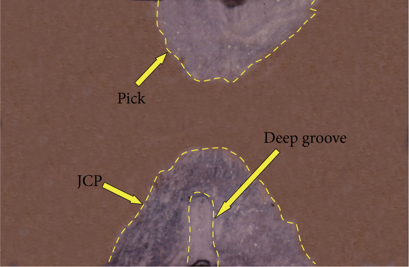
Results with cutting depth 19 mm.
It can be seen in Figure 13 that the effect of rock breaking by only a pick is worse than the JCP under the cutting depth 19 mm. And a deeper groove is formed by the JCP on the rock sample, and the breaking volume is bigger than only a pick. It indicates that the cutting depth can be improved by the assistance of the water jet.
5. Conclusions
The method of combining SPH algorithm and FEM is adopted to establish the numerical model of rock breaking, which provides a new method to research the mechanism of rock fracture. And the numerical simulation results of the three styles (a pick, the JFP, and the JCP) of rock breaking are compared, and the effect of JCP is the best.
In simulation, comparing with the cutting force of a pick, the cutting force of the JFP reduces by 9.52%, 7.92%, 4.91%, and 3.14% with the cutting depth of 7 mm, 11 mm, 15 mm, and 19 mm, respectively, when the pressure of the water jet is 40 MPa and the distance of the water jet placed in the front of pick is 2 mm, while the cutting force of JCP decreases by 23.5%, 21.88%, 15.09%, and 11.44%. While in experiment, the cutting force of the JCP decreases by 28.61%, 20.27%, 16.48%, and 14.13% with the cutting depth of 7 mm, 11 mm, 15 mm, and 19 mm, respectively. Thus, the results of simulation models are approximated with the experiment, which indicates that the simulation models are correct. The simulation showed that the JCP is better than JFP.
In the process of rock breaking by the pick assisted by water jet, the rock debris of crushed zone in front of pick can be washed away timely by water jet, and most energy of the pick can be affected on the new free surface of rock to improve the efficiency of rock breaking.
When the cutting depth of rock is large, the rock breaking by a pick is more difficult, while it is easy with the assistance of the water jet, and the crushed volume of rock can be improved. It illustrates that the rock breaking by pick assisted with water jet can improve the cutting depth of rock and the cutting performance of the pick.
Conflict of Interests
The authors declare that there is no conflict of interests regarding the publication of this paper.
Footnotes
Acknowledgments
This project is supported by National High-Tech Research and Development Program of China (863 Program) (no. 2012AA062104), National Natural Science Foundation of China (no. 51375478), the Jiangsu Provincial Natural Science Foundation of China (no. BK20131116), the Fundamental Research Funds for the Central Universities (Project no. 2012QNA22), and the Priority Academic Program Development of Jiangsu Higher Education Institutions.