
Abstract
Several types of electromagnetic transducer for the middle ear implants (MEIs) have been developed as an alternative to conventional hearing aids for the rehabilitation of sensorineural hearing loss. Electromagnetic transducer type and design are thought to have a significant influence on their hearing compensation performance. To investigate these effects, a middle ear computational model was constructed based on a complete set of microcomputerized tomography section images of a human ear. Its validity was confirmed by comparing the model predicted motions with published experimental measurements. The result shows that the eardrum driving transducer (EDT) is superior to the floating mass transducer (FMT) in hearing compensation when the transducer mass is small but inferior to the FMT when the mass gets bigger. The incus body driving transducer (IBDT) is the most ineffective type of transducer for hearing compensation. Moreover, the masses of the EDT and the FMT decrease the transducer performance mainly at higher frequencies: the greater the transducer mass, the lower the displacement of the stapes excited by these transducers. On the other hand, the IBDT driving rod stiffness decreases transducer's performance severely at low frequencies and its adverse effect on transducer performance increases with the decrease of the stiffness of the IBDT driving rod.
1. Introduction
To overcome the problems inherent in traditional hearing aids such as sound distortion, limited amplification, and wearing discomfort, middle ear implants (MEIs) have been developed over the past two decades [1, 2]. The main components of the MEIs can be divided into four parts, a microphone, an audio processor, a battery, and a vibration transducer. Among them, the transducer is a critical component, as it generates the vibration to the middle ear. The transducers used in the middle ear implants are either piezoelectric ceramic or electromagnetic induction devices. Electromagnetic transducers are widely investigated as their vibration efficiency is higher than that of piezoelectric transducers, and they do not require a high voltage driver [3].
Up to now, a great variety of electromagnetic transducers have been proposed. In terms of their attachment points in the middle ear system, the commonly used MEI electromagnetic transducers can be divided into three types: the eardrum driving transducer (EDT, attached to the eardrum) [4–6], the floating mass transducer (FMT, attached to the incus long process) [7, 8], and the incus body driving transducer (IBDT, attached to the incus body) [9–11]. To figure out which type of electromagnetic transducers is efficient for hearing loss compensation, Stieger et al. conducted a comparative experimental study and concluded that the FMT generates smaller displacements at low frequencies (<800 Hz), while the IBDT is efficient over the entire frequency range [12]. In contrast, based on computer simulations, Bornitz et al. reported a different result that the IBDT performance is worse than other types of electromagnetic transducers [13].
The implantation of these electromagnetic transducers requires placing an additional mass loading (the EDT or the FMT) or a stiffness constraint (the IBDT) on the ossicular chain of the middle ear. To investigate the effect of these design parameters on MEI implantation, a lot of studies have been conducted. Gan et al. experimentally studied the mass loading effect of the FMT by adding 22.5 mg to 37.5 mg of mass to the incus long process [14]. They concluded that the mass of the FMT has a great effect on human residual hearing, with a high mass causing a greater deterioration in patients’ hearing. Perkins clinical report indicates that patients’ mean hearing threshold shifts with the implantation of an EDT on the eardrum [15]. Bruschini et al. implanted an IBDT on patients and found that the mean deterioration of patients’ postoperative hearing thresholds was 3.5 dB [16]. Nevertheless, all the above studies focused on the effect on patients’ residual hearing, that is, on the external acoustic stimulated ossicular movements. To the authors’ knowledge, there is still no systematic report on the effect of these transducers’ design parameters on MEI hearing compensation performance.
As noted above, although several types of MEI electromagnetic transducers have been developed, engineering aspects for transducer performance influence have not been studied systematically. In this paper, FE analysis was conducted to characterize the influences of type and design on the performance of the transducers. The theoretical result is intended to assist the surgeon in choosing an adequate type of the transducer and to support the optimization of the transducer in order to insure sufficient output.
2. Materials and Methods
As the human middle ear is a tiny but complex structure, it is difficult to investigate the influence of transducer type and design parameters on the excited middle ear movement using experiments on temporal bones. Finite element (FE) modeling is capable of easily modeling the complex geometry, ultrastructural characteristics, and nonhomogeneous and anisotropic material properties of biological systems [17, 18]. Thus, we first constructed a middle ear finite element model. Then we took advantage of this model to study the above mentioned influences on transducer performance.
2.1. Establishment of the Middle Ear Finite Element Model
A middle ear finite element model was established to help study the dynamic characteristics of the middle ear system. The model consisted of eardrum, ossicles (malleus, incus, and stapes), ligaments, and tendons. The geometries of the ossicles and the eardrum were constructed based on a set of microcomputed tomography (GE Healthcare, eXplore Locus SP) images from the left ear of a 45-year-old healthy subject [9, 19]. The scanning was performed with a collimated slice thickness of 13 μm. These images were then reconstructed using a standard algorithm at overlapping intervals to improve the through-plane spatial resolution. After that, all of these images were transferred to Mimics (Materialise, Leuven, Belgium) for three-dimensional reconstruction of the middle ear. The reconstructed three-dimensional model was transferred to Geomagic Studio (Geomagic, North Carolina, USA), a commercial reverse engineering package, and a geometric solid model was established.
Using a finite element package ANSYS (ANSYS, RI, USA), the geometric solid model was used to create a geometrically precise finite element model of the ossicles by four-node tetrahedral solid elements (SOLID45) with a total of 19744 elements and the eardrum by three-node shell elements (SHELL63) with a total of 1569 elements. The final established middle ear FE model is shown in Figure 1. The characteristic dimensions of the FE model's components was listed in Table 1, which shows that most dimensions of current model are within the range of published middle ear anatomical data [20].
Dimensions of the human middle ear finite element model.


Finite element model of the human middle ear.
2.2. Material Properties
The human middle ear can be taken as a linear system under the regular sound intensity of the hearing level for acoustic-mechanical transmission from the eardrum to the cochlea [21]. Therefore, the materials of the middle ear system were assumed to be linear elastic. As Funnell and Laszlo stated that it had not been necessary to introduce anisotropy to construct the middle-ear model, all components of current model were also assumed to be isotropic [22]. The Poisson's ratio was assumed to be 0.3 for all of the components of the middle ear system [21]. Rayleigh damping was used to model the damping of the soft tissue structures of the middle ear. The Rayleigh damping assumes that damping is a linear combination of mass and stiffness according to

The Rayleigh damping parameters α and β for all materials of the middle ear system were taken as α = 0 s−1, β = 0.0001 s [23]. The malleus, the eardrum, and the incudomalleolar and the incudostapedial joints were connected by coupling of the corresponding finite element nodes. The material properties of the ossicles, eardrum, and joints were ascertained based on published data [23–25] (Table 2).
Material properties of the ear components.

2.3. Boundary Conditions
The five major ligaments (superior malleolar ligament, anterior malleolar ligament, lateral malleolar ligament, posterior incudal ligament, and stapedial annular ligament) and the tensor tympani tendon were assumed as elastic constraints with four-node tetrahedral solid elements (SOLID45). The annular ligament of the eardrum was meshed by three-node shell elements (SHELL63). The end nodes of all the ligaments and muscles were fixed to zero displacement. The action of the cochlear fluid on the stapes footplate was modelled as a set of 43 spring-dashpot elements distributed on the footplate. The detailed modelling properties for the boundary conditions are shown in Table 3 [23, 26, 27].
Boundary conditions of the middle ear FE model.

2.4. Transducer Models
Three types of MEIs’ electromagnetic transducers were analyzed:
eardrum driving transducer (EDT, e.g., EarLens, EarLens Corporation [5]) (Figure 2(a));
floating mass transducer (FMT, e.g., VSB, Vibrant Med-El Gmbh [7]) (Figure 2(b));
incus body driving transducer (IBDT, e.g., Carina, Otologics LLC [16]) (Figure 2(c)).

Schematic view of three MEI transducers. (a) Eardrum driving transducer consisting of coil placed in the ear canal and permanent magnet attached to eardrum; (b) floating mass transducer (FMT) attached to incus long process via a clamp; (c) incus body driving transducer coupled to incus body via driving rod.
As our main concern is the influence of the transducer type and design on the MEI performance, not the transducer working mechanisms, some simplification methods were adopted in the modeling process. For the EDT and the FMT, their transducers are totally supported by the middle ear component (eardrum for the EDT, incus for the FMT). Thus, the performance of these types of transducers is mainly influenced by their transducer mass. To study this mass loading effect, the EDT and the FMT were both modeled using four-node tetrahedral solid elements (SOLID45), ignoring their transducer inner structure. The final established coupling mechanical models are shown in Figures 3(a) and 3(b).

Finite element model of (a) EDT (eardrum driving transducer) implanted middle ear; (b) FMT (floating mass transducer) implanted middle ear; (c) IBDT (incus body driving transducer) implanted middle ear.
For the IBDT, its transducer is stabilized on the skull by a mounting bracket with its driving rod attached on the incus body. Therefore, the IBDT mass loading is mainly supported by the skull and has less effect on the MEI hearing loss compensation behavior. The vibration of the middle ear stimulated by this type of transducer is prominently constrained by its driving rod. Considering that the stiffness of the transducer basis is far bigger than that of the driving rod and the transducer driving force was applied by the driving rod, we simplified the transducer by just modeling the driving rod using 6 beam elements (BEAM188), as shown in Figure 3(c). The driving rod is 0.5 mm in diameter and 2.0 mm in length. With the purpose of investigating the driving rod stiffness effect on transducer performance, Young's modulus of the driving rod was varied to 116 GPa (titanium driving rod) and 510 GPa (ceramic driving rod).
As an ideal electromagnetic transducer is a force driven transducer (which provides a certain force without limitations in displacement) [13], all the exciting forces generated by these electromagnetic transducers were simulated using a sinusoidal force applied directly onto the transducer along the piston direction of stapes displacement (as shown in Figure 3). This direction was selected since it is the most efficient driving direction for all of the three types of transducers [13].
3. Results
3.1. Verification of the FE Model
To attempt to establish the extent to which the prediction of the middle ear finite element model accords with reality, a comparison against two experimental studies was done.
Aibara et al. [28] experimental data of stapes footplate velocity transfer function (STF) obtained from 11 fresh temporal bones were initially selected for the model verification. For comparison, a uniform pressure of 90 dB SPL on the lateral side of the eardrum was applied to current middle ear FE model. A harmonic analysis was conducted on the model across the frequency range of 160–8000 Hz. Then the STF was calculated according to (2). The calculated STF was plotted with the mean and the upper and lower bounds of the eleven experimental curves in Figure 4. It shows that our model-predicted STF curve lies relatively close to the mean of the experimental curves. It also appears that current simulated middle-ear resonance frequency (1280 Hz) is close to the mean experimental data (1236 Hz). However, the simulated resonance is not as obvious as the experimental curve. This may be because the damping we adopted is strong for this individual temporal bone. Nevertheless, this middle ear FE model is able to simulate the behavior of an average human middle ear system. Consider

where υ is stapes velocity, PTM is sound pressure at umbo, f is frequency, and D is stapes displacement.

Comparison of the FE model predicted stapes velocity transfer function with the experimental data.
The experimental data of umbo displacement published by Nishihara and Googe [29] were also selected for current model evaluation. With a uniform harmonic pressure stimulus of 80 dB SPL applied to the lateral side of the eardrum in current middle ear FE model, a harmonic analysis was conducted across the frequency range of 160–8000 Hz. The predicted umbo displacements were plotted with the experimental curves in Figure 5. Likewise, the FE model-predicted umbo displacement is close to the mean experimental curve in most of the frequency range.
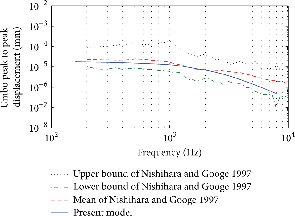
Comparison of the FE model predicted umbo displacement with the experimental data.
The above comparisons show that current middle ear FE model predictions, in general, are in satisfactory agreement with experimental results obtained from human temporal bones. Therefore, despite the approximations made, this middle ear FE model is able to simulate the behavior of an average human middle ear system.
3.2. Effects of the Transducer Type on the MEI Performance
As sound was transferred from stapes to cochlea, the stapes displacement is used to assess the MEI hearing compensation performance. To concentrate on the effect of the transducer type, we simulated each type of transducers by directly applying the driving force to their attachment points at the ossicular chain (umbo of the eardrum, incus long process, and incus body as shown in Figure 1) in this section, ignoring the specific structures of the corresponding transducers.
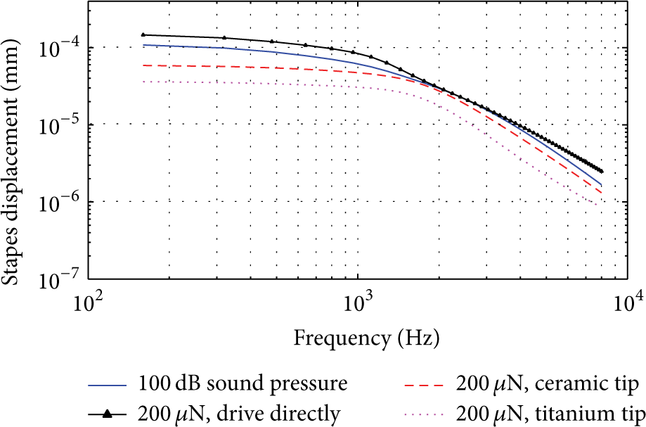
Many MEI developers used 100 dB SPL as their transducer maximum amplified sound pressure level, since excessive amount of sound pressure would cause sensory nerve pain [30]. In current simulation, we also selected 100 dB SPL stimuli at the eardrum as a reference for the comparison study. Figure 6 shows current model predicted stapes displacements for different types of the electromagnetic transducers. The result shows that, when the transducer attached to the incus long process (i.e., for FMT), the force required to stimulate the vibration of ossicles to the equivalent of 100 dB SPL is about 89 μN. This result is consistent with Ko et al.'s former report [31]. For EDT, that is, the transducer attached to the umbo, the required driving force decreased to 60 μN. On the contrary, when the transducer attached to the incus body (i.e., for IBDT), the required driving force for the transducer increased to 200 μN.

Stapes displacements excited by electromagnetic transducers attached at different points of the ossicular chain.
Therefore, compensating a similar level of hearing loss, the IBDT requires the biggest driving force, while EDT requires the smallest one. In other words, under a same level of driving force, EDT compensates hearing loss more efficiently than FMT, and IBDT performs the worst.
3.3. Effects of the Transducer Design on the MEI Performance
First, the effect of the EDT mass on the MEI performance was investigated by comparing stapes displacements under various transducer weights (Figure 7). To investigate the mass loading effect, we change the material of the EDT from aluminum to titanium and zinc, and the mass of the transducer weighs 16 mg, 27 mg, and 43 mg, accordingly. Figure 7 shows that the mass of the EDT does not influence the transducer excited stapes displacement significantly at lower frequencies (below 1000 Hz). When the frequency increases, the excited stapes displacement starts to decrease with the adding of the EDT mass. Moreover, the greater the EDT mass, the greater the decrease of excited stapes displacement at the higher frequencies (above 1000 Hz).

EDT stimulated stapes displacement with different mass loading.
To study the mass loading effect quantitatively, we selected the stimulated stapes displacement for the direct drive as the reference. Results for all mass weights of transducers are presented as the ratio to this reference, as calculated in the following equation:
where d tr is stapes displacement excited by ideal electromagnetic transducer (ignoring the structure and the mass of the transducer) and dtr_m is transducer excited stapes displacement considering the mass (or rod stiffness for IBDT) of the transducer.
Figure 8 shows that the maximum decrease of the transducer excited stapes displacement is around 13 dB at 8000 Hz for the 43 mg transducer.

Change of transducer excited stapes displacement with the change of the EDT mass.
Next, the effect of the FMT mass on the transducer performance was studied (Figure 9). By changing the material of the FMT from aluminum to titanium and zinc, we got the simulated mass of the FMT weighting 15 mg, 22 mg, and 32 mg, respectively. Similarly to the EDT, the FMT mass loading does not impact the transducer excited stapes displacement significantly at lower frequencies (below 750 Hz). As the frequency of the stimulation further increases, the mass loading of the FMT starts to decrease the stapes displacement excited by the transducer. This deterioration of transducer excited stapes displacement changes significantly with the adding of the mass. The maximum drop in stapes displacement is around 7.9 dB at 6000 Hz for the FMT with 32 mg mass (Figure 10).

FMT stimulated stapes displacement with different mass loading.

Change of transducer excited stapes displacement with the change of the FMT mass.
The driving force of the FMT is transferred to the incus long process by the clamp (Figure 2(b)). To investigate the influence of the clamp's material, Young's modulus of the clamp was changed from current 116 GPa (titanium clamp) to 510 GPa (ceramic clamp). The result (Figure 11) indicates that the material variation of the FMT clamp produces little difference in the excited stapes displacement over the entire frequencies. Figure 12 demonstrates that the ceramic clamp can only produce a small increase in the FMT excited stapes displacement at frequencies above 1600 Hz relative to the titanium clamp. The maximum increase in transducer excited stapes displacement is just 0.6 dB at 8000 Hz.

FMT stimulated stapes displacement with different clamp material for 22 mg transducer mass.

Ratio of equivalent sound pressures of the FMT for ceramic clamp. Reference is the FMT excited stapes displacement for titanium clamp (with 22 mg transducer mass).
Finally, the effect of the IBDT driving rod stiffness on stimulated stapes displacement was investigated by changing the material elastic modulus of the driving rod (Figure 13). The result shows that the insertion of the driving rod reduces the transducer excited stapes displacement over the entire frequencies. And this decrease shows more significant at lower frequencies (below 1000 Hz). In addition, this side effect on transducer performance becomes more serious when the driving rod's stiffness decreases. Likewise, to investigate the rod stiffness effect quantitatively, the change of the stapes displacement with the adding of the rod is expressed in decibels as calculated in (3). The results were plotted in Figure 14, which indicates that the maximum drop in transducer excited stapes displacement is around 12.5 dB at l60 Hz for transducer with titanium driving rod. The transducer with ceramic driving rod resulted in a maximum drop of 8 dB at 160 Hz.
IBDT stimulated stapes displacement with different driving rod material.

Change of transducer excited stapes displacement with the change of the driving rod material of IBDT.
4. Discussion
4.1. Effect of the Transducer Type on the MEI Performance
We have obtained comparative result on three typical types of electromagnetic transducers for middle ear implant. These transducers are classified by their coupling sites and represent eardrum driving transducer (EDT), floating mass transducer (FMT), and incus body driving transducer (IBDT), respectively. Our result suggests that for ideal electromagnetic transducers (i.e., ignoring the transducer structure), the EDT is the best transducer type as it can compensate 100 dB sound pressure with the smallest driving force (60 uN). On the other hand, the FMT and IBDT require 89 uN and 200 uN, respectively. This result is consistent with a previous report [13]. However, when we considered the actual structure of the transducer, the EDT performance was more sensitive to transducer mass loading than that of FMT. Current model predicted result shows that the required driving force of EDT increased to 119 N when the transducer mass was 27 mg, while the corresponding driving force for FMT only increased to 115 N. Therefore, the FMT performance is superior to that of EDT when their transducers have a mass greater than 27 mg.
In terms of hearing compensation, the IBDT is the most critical type of MEI transducers, as it requires the highest driving force than the one required by the other two types of transducers. This may be because the force action point of IBDT is near the rotational axis of ossicular chain vibration modes [27]. Thus, the IBDT generates ineffective movements.
4.2. Effect of the EDT Mass Loading on the MEI Performance
Hamanishi et al. [6] temporal bone experiment showed that the EDT's mass loading deteriorated patients’ residual hearing at high frequencies, whereas the influence of the EDT's mass on transducer stimulated performance was not reported. Our result indicates that the EDT excited stapes displacement is also decreased by the mass loading of the transducer at the high frequencies (above 2000 Hz) but increased slightly at lower frequencies around 1000 Hz. This is mainly because the mass loading of the transducer shifts the resonance of the middle ear system toward lower frequencies. Moreover, our result shows that the addition of the EDT mass has a detrimental effect on the transducer performance. The greater the EDT mass, the greater the decrease of excited stapes displacement, particularly at the high frequencies. This effect is extremely detrimental to the middle ear implant performance, as sensorineural hearing loss is usually most severe in the high frequencies [32]. Therefore, in the design of the eardrum driving type of middle ear implant, the small mass of its transducer is an important requirement.
4.3. Effect of the FMT Mass Loading on the MEI Performance
The mass loading effect of the FMT has been studied both in middle ear modeling studies and in temporal bone experiments. Needham et al.'s temporal bone experimental report [33] showed that the implantation of the FMT weighed 25 mg decreased stapes displacement mainly at higher frequency (above 1000 Hz). Wang et al.'s model simulation result [34] also confirmed the decrease of the stapes displacement by the adding of the FMT's mass. However, all of these investigations were focused on the stapes displacement stimulated by external acoustic, that is, patient's residual hearing. In terms of the influence on the FMT hearing compensation performance, to the authors’ best knowledge, there are very few studies in the literature on it. Our result indicates that the FMT mass also deteriorates the transducer hearing compensation, especially at high frequencies. Our result also shows that the deterioration level of hearing compensation performance increased with the addition of the FMT mass. Hence, in the design of the FMT, the mass of its transducer should also be restricted.
To compare the FMT mass loading effect with the one of EDT, the maximum drop in stapes displacement for different mass weights of each type of transducer was plotted in Figure 15. It shows that under a similar level of transducer weight, EDT performance decreased more than that of FMT. Thus, the EDT performance is more sensitive to the transducer mass weight than that of FMT.

The effect of transducer mass on the transducer excited stapes displacement.
4.4. Effect of the FMT Clamp Material on the MEI Performance
Wang et al.'s report [34] shows a firm crimping connection between the clamp and the ossicles that can maximize the efficiency of the transducer stimulation, especially at frequencies above 2000 Hz. Nevertheless, to the authors’ best knowledge, there is no research on the influence of the FMT clamp material. Our result demonstrates that changing the clamp material of current FE model from titanium to ceramic increases the transducer hearing compensation at frequencies above 1600 Hz. The maximum increase is 0.6 dB at 8000 Hz. However, this impact is much small compared to the effect of FMT mass loading. Hence, in the design of the FMT, commonly used titanium clamp is adequate for FMT vibration transfer.
4.5. Effect of the IBDT Driving Rod Stiffness on the MEI Performance
Clinically, the implantation of an IBDT with a titanium tip on patients can deteriorate patients’ postoperative hearing mean thresholds 3.5 dB [16]. However, our result suggests a titanium driving rod would decrease the IBDT excited stapes displacement 12 dB (at 160 Hz), which is bigger than 3.5 dB. Therefore, the IBDT hearing compensation performance is more sensitive to the transducer driving rod stiffness than patients’ residual hearing. Thus, in view of the improvement of the IBDT performance, the stiffness of its driving rod should be more strict. In addition, current model predicted result shows that the deterioration level of the IBDT performance changed with the driving rod material. Compared to the titanium driving rod, the ceramic driving rod with the larger elastic modulus dropped the IBDT excited stapes displacement less significantly. Thus, in terms of the IBDT hearing compensation performance, a driving rod with the larger elastic modulus is preferred.
5. Conclusion
Finite element model is utilized to examine the effect of transducer type and design on the hearing compensation behavior of electromagnetic middle ear implants. The model was built based on a complete set of computerized tomography section images of a left ear by reverse engineering technology, and its validity has been verified by comparing the model predicted movements with published experimental data. The result shows the following.
The EDT is an optimal type of electromagnetic transducer for hearing compensation, when the mass of the transducer is too small, whereas the FMT performance is superior to that of the EDT, when the mass of the transducer gets bigger. The IBDT is the most ineffective transducer type in hearing compensation.
The mass loading of the EDT and the FMT decrease transducer performance prominently at the higher frequencies: the greater the transducer mass, the greater the decrease of transducer excited stapes displacement at higher frequencies. Thus, weight should be restricted in the design of these two types of transducers.
The driving rod's stiffness of the IBDT decreases the performance of the transducer severely at low frequencies. Adverse effect on transducer performance increased with the decrease of the stiffness of the transducer driving rod. Thus, in terms of the IBDT hearing compensation performance, a driving rod with the larger elastic modulus is preferred.
Conflict of Interests
The authors declare that there is no conflict of interests regarding the publication of this paper.
Footnotes
Acknowledgments
The research work was supported by the National Natural Science Foundation of China (Grant no. 51305442), the Jiangsu Provincial Natural Science Foundation (Grant no. BK20130194), the Specialized Research Fund for the Doctoral Program of Higher Education (Grant no. 20130095120010), the Fundamental Research Funds for the Central Universities (Grant no. 2012QNB16), and the Priority Academic Program Development of Jiangsu Higher Education Institutions. The authors also are grateful to Francisco D. Denia and anonymous reviewers for detailed comments and suggestions.