
Abstract
Due to the complex geometry of plate heat exchangers and thus a large number of variables affecting the performance of the exchangers, the design of these types of exchangers is quiet difficult. However, unlike the shell and tube heat exchangers which contain available data of design procedures, the design of plate heat exchanger is a monopoly of some certain manufacturing companies that make the problem even worse. In this paper, the objective is to minimize the number of plates in plate heat exchanger; in order to achieve that, a simple and yet efficient mathematical model is introduced for determination of the pressure drop and heat capacity of a plate heat exchanger in single- and multipass state and also a program was defined for determination of optimal solution based on this simple mathematical model for given operational constraints and plate type. In the end, the optimal solution will be compared to the answer of CAS200 commercial software and also it is shown that the effect of the start and end plates and transverse distribution in optimal solution is considerable.
1. Introduction
The increase in global consumption, on one hand, and enactment and enforcement of strict environmental laws, as well as the development of other industrial countries, on the other hand, has led energy costs to rise. One of the most important strategies for saving energy is to create productive closed-cycle with nonpolluting products, while making optimum use of heat generated in a process; this requires efficient and economical manufacturing of heat exchanger. Manufacturing a fine product requires optimization of the production process, heat, and energy.
Today, heat exchangers are widely used in food and pharmaceutical and chemical industries, so selecting an appropriate heat exchanger is one of the major concerns of today's engineering industry. These heat exchangers not only must be able to meet the needs of the process but also do not impose too much investment and operating and maintenance costs. Shell and tube heat exchangers have been used for many years, but, in the past decade, the demand for plate heat exchanger (PHE) has increased.
Compared to other heat exchangers higher compression ratio, less total cost, less sediment, and flexibility of the change of heat transfer surfaces are of the positive features of these types of heat exchangers which results in an increasing tendency toward PHEs. Due to variation in PHEs design that can be suitable for different thermal tasks, the design of such heat exchangers is very specialized, and manufacturers of PHEs utilize elaborated computer design techniques. The main characteristic of PHE design is the fact that the conditions required for the heat transfer process are provided using a number of different plates. As a matter of fact, required heat transfer area is a function of plate type, number of passes, and composition of plates with different corrugations pattern; therefore determination of optimal solution which has the minimum possible heat transfer area is complex.
The common methods of PHE's design and how to establish connection between heat transfer and pressure drop were presented by Shah and Wanniarachchi [1]. But in these methods effective parameters were not mentioned. Due to the complexity of optimization of PHE and plurality of effective parameters, determination of optimal pattern of plates is difficult. The effect of the plate pattern's angle on thermohydraulic performance of plate heat exchanger was examined by Focke et al. [2]. The impact of other effective parameters on the heat capacity, which, in fact, is flow distribution in plate heat exchanger (PHE), was represented by Prabhakara Rao and colleagues [3]. The major problem of this model is that the effect of distribution is sensitive to the axial dispersive Peclet number and plate numbers while it is practically independent of NTU and heat capacity rate ratio. In the field of optimization the performance of PHE, simultaneous optimization of both energy and heat transfer area, was performed by Yee et al. [4] for thermal integration in multistream PHE model. In 2003, the optimal design of PHE which does not contain many trials was offered by Wang and Sundén [5] in two cases, namely, with and without taking pressure drop determination into account. Moreover, in the field of optimization of PHEs, numerical work was presented by Park et al. [6]. In 2004, a screening method for selecting optimal configuration of PHEs was published by Gut and Pinto [7] and later a general method for the optimal design of plate heat exchangers (PHEs) was presented by Kanaris et al. [8] in which a CFD code has been utilized to estimate the heat transmission rate and pressure drop.
One of the most common problems is gasket failure which happens due to high operating temperature. In recent studies the effect of plate thickness on the peak temperature has been investigated by Hajmohammadi et al. [9–12]. It is shown that there is an optimal thickness of the thick plate, minimizing the peak temperature.
A key parameter in the design and selection process of heat exchangers is the efficient area of heat transfer calculated based on the heat load. Besides, economical design of heat exchanger is in fact the allowed pressure drop for determining efficient area of desired heat transfer. In general, a PHE design is based on trial and error. For this purpose, first, the efficient area of heat transfer was obtained, and then the PHE pressure drop is calculated based on this selection. If this value is less than or equal to the allowable pressure drop, the design will be acceptable; otherwise, it will be redesigned. The objective of the present paper is to develop a new algorithm based on a mathematical model to minimize the number of plates in PHEs based on specific inputs such as maximum pressure drop and required heat transfer, although at times it is required to optimize fluid flow and/or heat transfer in which entropy generation minimization (EGM) method is used to find optimum fluid flow and/or heat transfer characteristics. In the end, the results of the program for a series of Alfa Laval heat exchangers (M3, M6, and M6M) are studied.
2. Mathematical Model of Plate Heat Exchanger
In order to choose the correct selection of PHE, a mathematical model is required to investigate the performance of different options. The best option is to be selected according to data available in the commercial plates.
Determination of mathematical model for plate heat exchangers is obtained by considering the following hypotheses [13].
No phase change occurred in flows.
The number of heat transfer plates is enough so that heat transfer conditions for the end plates and on edge of pass plates are of difference with other plates.
Flow misdistribution in collectors can be neglected.
In the collector, each channel of flow is mixed thoroughly together.
To explain mathematical model of the PHE, consider a multipass PHE as in Figure 1. With regard to the above conditions, the multiple-pass PHE in this figure can be divided into several single-pass PHEs; the number of the PHEs is equal to multiplication of the pass between the hot and the cold, so the PHE in Figure 1 can be divided into nine single-pass PHEs (Figure 2) because both hot and cold flows have three passes (X1 = 3, X2 = 3). The area of heat transfer of each of these blocks is equal to S b = S/(X1X2), where S is total area of heat exchanger.
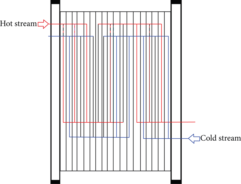
Passing flows through a multipass PHE.

The change of a multipass to a single-pass PHE.
Number of transfer units (NTU) for each of the heat exchangers is calculated by

where U b is heat transfer coefficient (W/m2·K), G1 is hot fluid mass flow (kg/s), and c1 is specific heat capacity of hot fluid (j/kg·K).
Assuming that R b = G1(c1/X2)/G2(c2/X1) < 1, then block heat exchange effectiveness ∊ b for parallel flow heat exchanger

And for counter flow heat exchanger,

In these relations,

where δT i is changes of hot fluid temperature in each block (K) and ΔT i is maximum possible temperature change of the fluid (K).
The above relations at R b > 1 are also true; however, they have different physical meanings. Therefore, by using the above relations, a mathematical model can be achieved in which the temperature change is a function of U b and S b .
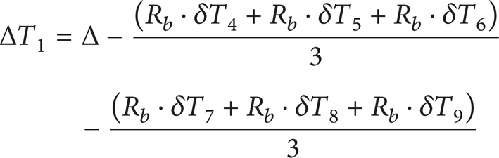
For each of the blocks (single-pass PHE) an equation can be driven so that it can relate changes in fluid temperature at each of them to the temperature of the fluid of other blocks.
Consider Block 1 in Figure 2 as an example where maximum possible temperature change is equal to difference between initial temperature difference (Δ) and increase rate of cold fluid temperature to Block 1; it can be shown as the following equation:
as we have ∊b1 = δT1/ΔT1,

These equations can be written for the other blocks, and, in fact, a linear system of equations is obtained which can be solved by determining the changes in temperature of each block:

In the general case, the coefficient matrix can be expressed as follows [13]:

where

These systems of equation have been created for the number of passes up to X1 = 7 and X2 = 6, with an overall counter flow arrangement [13]. After solving the above system of equations, the following series can be used to obtain changes in temperature of fluids [13]:
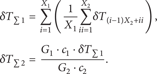
The overall heat transfer rate [13]
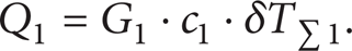
From the above equation it can be concluded that, to determine the amount of change in flow temperature, the rate of overall heat transfer coefficient (U b ) should be known; this parameter is determined according to heat transfer equation [14]:
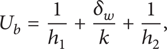
where δ w is wall thickness (m), h1 is convection coefficient of hot fluid (W/m2·K), h2 is convection coefficient of cold fluid (W/m2·K), and k is thermal conductivity of wall (W/m·K).
For determining the convection coefficient (h1, h2), the following empirical relationship is normally applied [13]:
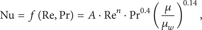
where

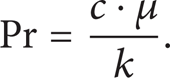
where d e is channel equivalent diameter (m). Consider
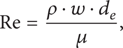
where ρ is density (kg/m3), w is velocity in the channel (m/s), μ is dynamic viscosity at flow temperature (kg/m·s), and μ w is dynamic viscosity at wall temperature (kg/m·s). Consider
To determine the pressure drop in single-pass PHE, the following equation is utilized [13]:

where Δpp − c is pressure drop in the PHE collector and can be calculated as follows [13]:

(in order to determine the pressure drop in multipass PHEs, pressure drop of a single-pass PHE must be multiplied by the number of passes).
In the above equations one has the following:
l p is effective length of the plate (m);
wport is flow rate in the collector (m/s).
ξ is the friction coefficient obtained by the following empirical equation:

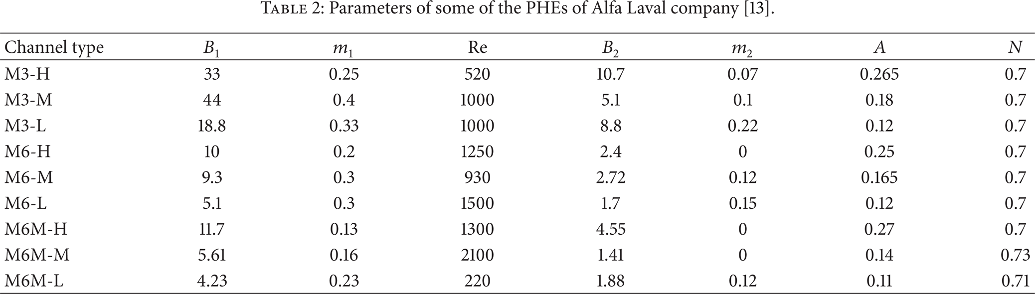
The parameters of convection coefficient (A, n) and the parameters of friction coefficient (B, m) are determined by Least Square method [13]. To determine these parameters geometric properties of PHE must be determined in which, in this case, Alfa Laval company's data has been used. The geometrical parameters of plates and inter-plate channels [13] are given in Table 1 and the obtained parameters of correlation [13] are given in Table 2.
Geometric properties of Alfa Laval company's heat exchanger plates [13].

b: plate width (mm).
Sch: cross-sectional area of each channel (m2).
Spl: cross-sectional area of each plate (m2).
δ: inter-plate gap (mm).
Parameters of some of the PHEs of Alfa Laval company [13].
3. Plate Heat Exchanger Optimization Algorithm
Based on this mathematical model a program should be written in such a way that its answers meet all thermal and hydraulic demands and contain the minimum number of plates compared to other answers, so some points must be regarded to increase the accuracy of program.
(1) Physical properties that are required in the calculations are fluid density (ρ), thermal conductivity wall (K), specific heat of the fluid (C), and liquid viscosity (μ). Values of ρ, K, and C had few changes in average temperatures, so it is a reasonable assumption to assume them as constant but viscosity in normal temperatures has a wide range of changes. In this program, to consider viscosity changes, three values of the viscosity at three different temperatures are considered: one near the inlet of channel, one near the outlet of channel, and the other one between these two.
(2) At the beginning of the flow entrance, due to the small thermal boundary layer, heat transfer coefficient is very large; as the flow is developing along the heat exchanger and increasing the boundary layer, the rate of convection coefficient decreases and reaches a constant value. The distance between the channel entrances to the location where the temperature profile no longer changes along the channel length is called the length of thermal boundary layer that can be obtained from the following equation [14]:
Laminar Flow:

Turbulent Flow:

Due to changes in convection coefficients along thermal boundary layer zone, this area is very important in determination of the heat transfer coefficients. In this program changes of convection coefficient were regarded by using average of it along channel length.
(3) How velocity is distributed in the channels of plate heat exchangers has been described by Wang et al. [15]; velocity and pressure distribution in the channels are obtained; for example, velocity and pressure distribution for U-type arrangement are like Figures 3 and 4. Based on these figures the greater pressure difference between the inlet and outlet port in a channel causes higher rate in this channel than the other channels. Nonuniform distribution of the flow causes nonuniform resistance to hydraulic flow; this phenomenon is more significant in horizontal rather than vertical flow and it also causes nonuniformity of heat coming from the fluid. In this program, the nonuniform distribution is considered by this distribution model.
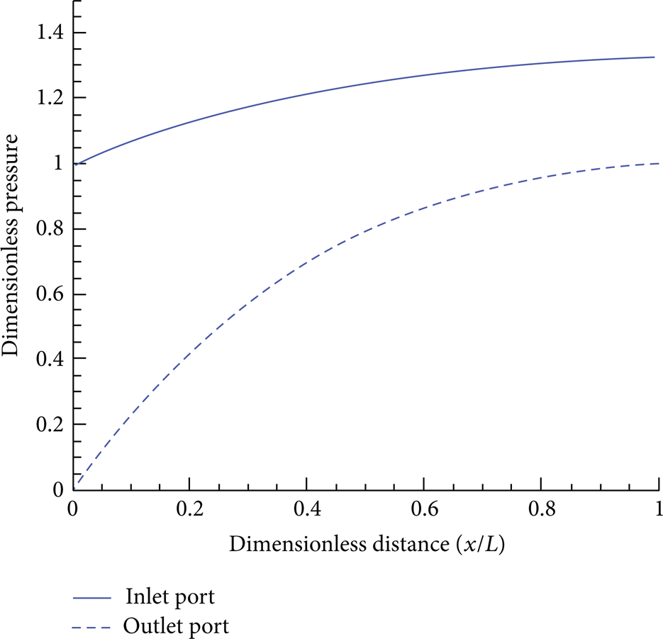
Pressure distribution in single-pass heat exchanger channels with U arrangement [15].
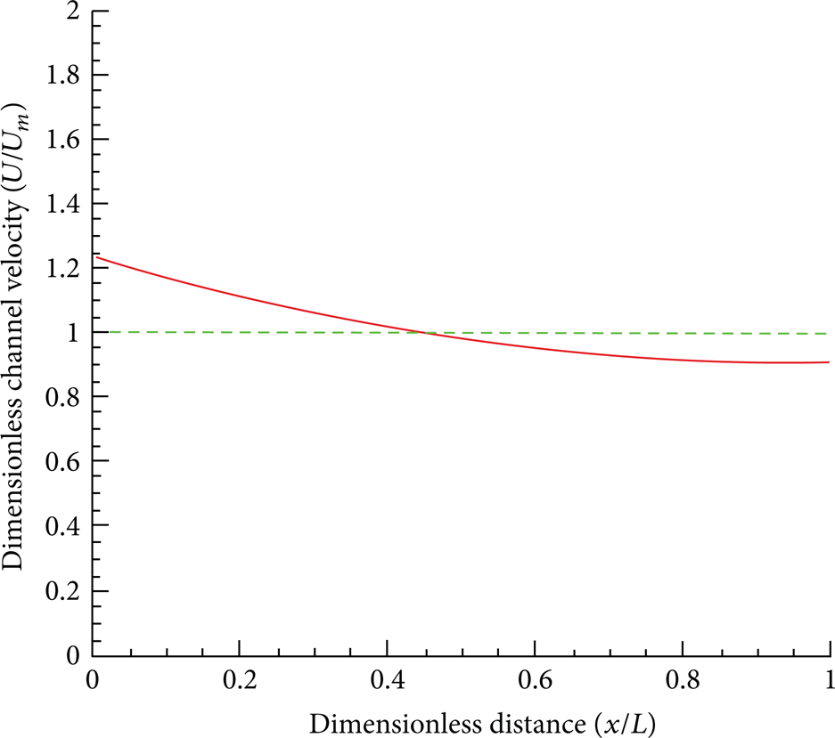
Velocity distribution in single-pass heat exchanger channels with U arrangement [15].
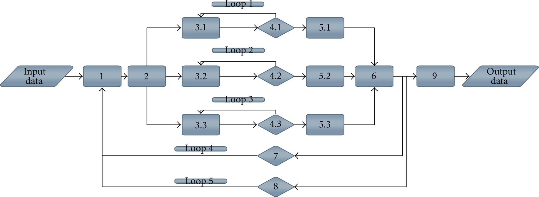
The main structure of the algorithm is as in Figure 6 and the steps of algorithm are as follows.
(1) The first step requires design requirements to be entered, like PHE type (plate type and plate material), fluids, heat transfer rate, maximum pressure drop of two fluids, input temperatures, mass flow of the fluids, and the margin.
(2) At the second stage, the minimum number of plates is determined according to (22) [13]; in fact, this relation determines the maximum mass flow rate of ith stream in one channel of the j-type according to the maximum pressure drop (this is done for three channel types of H, M, and L):

where Δp i o is maximum allowable pressure drop (pa) and v i is kinematic viscosity (m2/s).
(3) After determination of minimum number of allowed plates (due to pressure) in each of the channels at the third stage, the heat transfer rate of heat exchanger in this specified plate number is determined. (This step is done separately for each of three channel types.)
(4) At this stage, if the number of plates provides the required heat of heat exchanger, the program goes to step (5); otherwise, a plate is added to plates and the program goes to step (3). (This step is done separately for each of three channel types.)
(5) At this stage, the answer of each channel, which meets the requirements, is stored.
(6) In this step, of the three answers presented, the optimum answer that has the minimum number of plates is introduced.
(7) Loops are used to make the optimum answer in multipass PHEs mode; the 7th stage, in fact, is a loop increasing the number of cold fluid passes and thereby optimum answer is determined in several different modes of multipass.
(8) This step is similar to Step (7), except that it increases the hot fluid passes.
(9) At Stage (9), of all the different states (single-pass and multipass), the answer containing the minimum number of plate is introduced as best answer of the program. Presented results include the number of plates, type of channel, and pressure drop of fluids (Figure 5).

Plate main dimensions.
Flowchart of algorithm.
4. Results
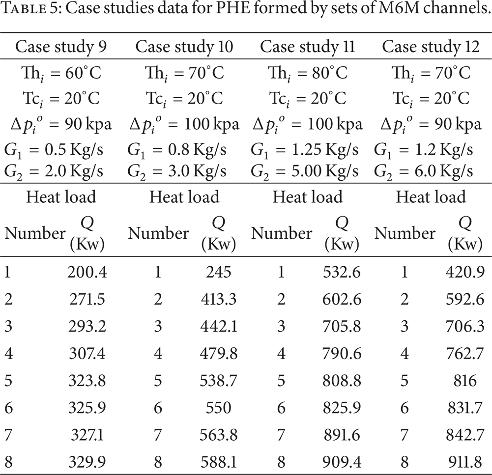
To determine the accuracy of the program, program results should be evaluated by correct result. In doing so, program's result for water is evaluated for a series of Alfa Laval heat exchangers (M3, M6, and M6M) in twelve case studies. Tables 3, 4, and 5 present the case studies data which involve initial temperature of hot and cold fluids, requirement heat load, maximum allowable pressure drop, and plate type. The difference between written program and result of CAS200 software [16] is shown as the error percentage of heat transfer area in the range of heat loads. As a matter of fact, because of positive correlation between heat load and number of plates, the accuracy of the program is investigated in wide range of plate numbers.
Case studies data for PHE formed by sets of M3 channels.

Case studies data for PHE formed by sets of M6 channels.

Case studies data for PHE formed by sets of M6M channels.
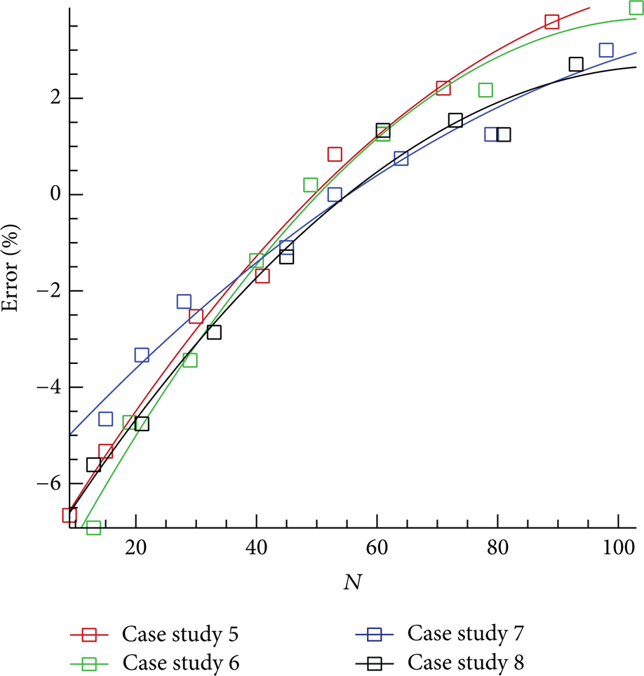
The error percentage is shown in Figures 7, 8, and 9. The general trend of the graphs is in small number of plates (low heat loads); error percentage is negative and, by increasing the heat load, it rises. The program's error in high heat loads in comparison to low ones has more accuracy. In addition, the more the fluid flow rate increases, the more the error rate decreases.
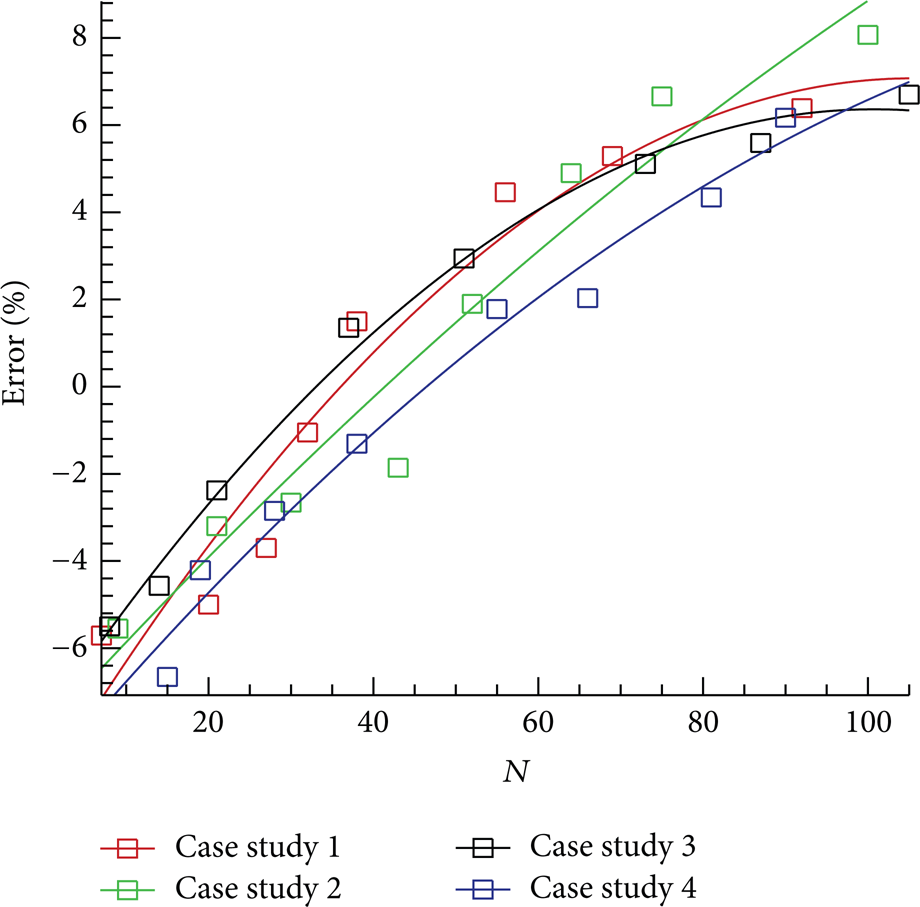
Error percentage of program results with the optimum results for PHE formed by different sets of M3 channels.
Error percentage of program results with the optimum results for PHE formed by different sets of M6 channels.

Error percentage of program results with the optimum results for PHE formed by different sets of M6M channels.
Causes of an error in the program are divided into two categories.
(1) The thermal effect of the start and end plates: end plate effect on PHEs with small plates has a substantial effect on heat transferring and reduces the heat capacity of it. Considering the effect of this factor on program requires a complicated model but in general method which is based on trial and error it is possible to regard it. Figure 10 shows a comparison between the result of trial and error method which is based on data obtained by Kandlikar and Shah [17] and CAS200 software for case study 1.

Comparison of results for case study 1.
(2) Transverse distribution of flow inside channels: this phenomenon occurring because of small size of both entry and end port of the plate in comparison with the width of the main heat transfer area leads to transverse temperature profile in channels. Although a transverse distribution in the plate heat exchanger design is an important issue, it is difficult to calculate and estimate it.
5. Conclusion
In this paper, a program was presented based on mathematical model proposed by Arsenyeva et al. [13] in order to find a PHE which not only meets thermal and hydraulic demand but also has the least number of plates. In this program the effects of maldistribution and thermal boundary layer on PHE were considered and the accuracy of the answer of case studies was checked by comparing solution with the correct answer using CAS200 software. The results show that in small number of plates, due to the effect of the start and end plates and transverse distribution, the heat capacity of PHE is less than excepted value, thus resulting in negative percent of error. As the number of plates increases, the effect of these factors decreases and the accuracy of program is enhanced. However the accuracy of program is acceptable; a more advanced algorithm is needed to achieve the upper accuracy. Further improvement can be made in future work by consideration of other factors such as end plate effect, transverse distribution, and fouling.
Conflict of Interests
The authors declare that there is no conflict of interests regarding the publication of this paper.