
Abstract
One of many optimization techniques is the evolutionary structural optimization (ESO), based on the idea that an optimal structure can be achieved by gradually removing ineffectively used materials from the design domain. Production of a multistage optimization is often proposed to reach the best overall solution. In the first stage, the structure is optimized according to a topology criterion, and, in the second stage, sizing optimization is carried out. The efficiency of such an approach is questionable as a fixed topology, for the second stage optimization may not be the most favorable before sizing optimization is carried out. In this paper, the simultaneous topology and size optimization of trusses using the ESO algorithm are discussed. A number of numerical examples are presented to research capacity to achieve optimal solutions for a structural problem. The topology design of the initial design domain is based on commonly used designs for multistorey trusses constructed from straight members. Therefore, the cases are of a slender shape and made from a combination of presented internal designs. The case studies will present an evaluation to show whether the described optimization approach can be beneficial in structural design for the purpose of steel framework designs.
1. Introduction
Two of the most commonly used steel structures in daily life are trusses and frames. Such structures can be employed in many engineering purposes, for example, telecommunication towers, transmission towers, and wind turbine towers, because they have some favorable properties, such as being simple in design and inexpensive to construct.
When designing such structures, it is very important to decide what the actual structure should look like. The loads and support conditions of a design problem are known in advance. Throughout the last century, the consumption of structural material has become the accepted criterion for the cost efficiency of a structural design. Therefore, weight reduction has become the main objective of the design task.
The optimization of structures has been a topic for many centuries, from Galileo, Bernoulli, Lagrange, Navier, and other great scientists who searched for the best shapes for structural elements to satisfy the given construction task. Over the years, this area of engineering has evolved into a discipline called structural optimization, where the most economical geometrical shapes that satisfy the given constraints (e.g., stress and deflections) imposed on the design are to be determined.
There exist some commonly used designs of trusses and frames that are used to solved a design task. Adapting an existing task for a new design is not beneficial. Therefore, the described design problem is better solved by a structural optimization approach. One could solve the problem by finding the most favorable design, but a problem with the element's cross-sectional size may still exist because it influences the weight of the structure. Therefore, in addition to finding the most suitable shape of a structure, the size of the element's cross-section has to be reduced to its minimum. With both shape and size optimizations, the construction process can be predicted, and the decision of which commonly used design of trusses and frames is most suitable to solve the construction task is much clearer.
2. General Optimization Problem Formulation
The formulation of an optimization problem begins with a statement that describes the overall objectives of the construction problem and the requirements to be met [1]. To develop a mathematical formulation of the problem, vital data, for example, material properties, performance requirements, resource limits, cost of material, and so forth, has to be gathered. Next, a set of variables, called design variables, that describe the system, has to be identified. The design variables should be independent of each other to the extent possible:

Whether this initial design satisfies all requirements is another question to be looked into. To evaluate the feasibility of different designs, we must have a criterion, which is called an objective function for the optimum design problem, which needs to be maximized or minimized depending on the problem requirements. The general formulation of the objective function is
In some situations, the requirements of a problem claim to have more than one objective function. These cases are called multiobjective design optimization problems. Some of the problem requirements are such that they represent restrictions of a design, and they are called constraints. All constraints must depend on the design variables because only then do their values change with different trial designs. In general, the formulation of the design constraints is of the form

Some constraints are quite simple, such as the limitation of the minimum and maximum allowable values of the design variables. Such restrictions are called implicit constrains and are formulated as

Different mathematical and numerical techniques can be employed to solve an optimization problem. These procedures can be specific for a certain problem formulation or can be adopted to gain the best solution of an optimization problem. Therefore, we must firstly define what type of problem we are dealing with before choosing the corresponding optimization technique.
3. Structural Optimization
Structural optimization is often divided into three classes, sizing, geometrical, and topology optimization, according to different authors [2–4]. Each of these classes has a different design objective to be optimized.
Sizing optimization. Dimensions of the element cross-section are chosen to be design variables. The values of the design variables are not allowed to be minimized to zero.
Geometrical optimization. The coordinates of the joints of the structures are chosen to be design variables.
Topology optimization. The number of structural members and the connectivity between members are considered.
There are cases where the above classification does not apply. The proposed terminology for structural optimization classes also varies in the literature.
Each of proposed optimization classes objectives and their design variables are independent of each other. In particular, in the case of sizing and geometrical optimization, the topology of a structure cannot be altered during the optimization process. It may happen that, after the optimization process is finished, the optimal solution may not be the best one or even a good one because different initial topology designs of a structure may produce a remarkably better solution for the construction task. The final solution can be misled by a poor initial design. Therefore, it is logical that the best overall structure can be produced using topology optimization. Using only one of the proposed classes does not produce the best overall structural solution. Therefore, an efficient structural optimization must be performed using several optimization classes.
Some researchers [2, 4, 5] have proposed a multistage structural optimization to produce the best overall solution. In the first stage, the structure is optimized according to the topology criterion, and, in the second stage, sizing optimization is carried out. There are some open questions [6] about the efficiency of such approach as a fixed topology may not be most favorable after sizing optimization is carried out. The best solution of an optimization process is obtained from combining optimization processes, where two stages are combined into a single stage optimization process. In this work, the optimization process is a combination of the topology and size optimization.
Topology optimization was pioneered by Michell [7]. From his analytical results, the Michell trusses, it has been found that, for the least-weight truss, each bar is subjected to the corresponding allowable stress value. The optimization approach, based on the described criterion, is called the fully stressed design (FSD) method [8, 9]. In a fully stressed state, each structural member is subjected to its maximum/minimum allowable stress value. The allowable stress value may be different for each component and for tension and compression. If the limiting stresses are equal for every structural component, the resulting FSD structure is also equally stressed. Topology optimization has been employed by different optimality algorithms [10–15].
An important development in topology optimization was made by Bendsøe and Kikuchi [10], who first introduced the homogenization method. Using this method, a finite number of cells construct the design domain. Each of these cells can be unique, having its own microstructure and material properties or containing a rectangular void. The use of a fixed finite element model for the design domain avoids the necessity of remeshing. The idea behind the homogenization method is to replace the layout problem of the material distribution by a much easier problem of seeking the optimal material distribution in a composite material. The method exploits the microstructural foundation of each cell by cutting small voids in the original homogeneous material. The design variables are presented by the ratio of solid/void parameters in the cells, and homogenization theory is used to compute the effective material properties. Further detailed information about the homogenization method can be found in the literature [10, 11, 16–19].
One of the popular methods for topology optimization is the solid isotropic material with penalization (SIMP) method [11, 20–22]. Similar to the homogenization method, the design domain is constructed by a finite number of cells, where each of them can have unique material properties. The design variable using this method is presented by the element density of each element. The discrete design variables are relaxed and are allowed to incorporate all values between its lower restrain x min and its upper restrain 1. The intermediate material stiffness may be penalized with the power-law, and the resulting topology tends to be close to a solid/void design. One of the disadvantages of this algorithm is that the solutions tend to produce checkerboard patterns [23].
Genetic algorithms (GA) have also been implied to solve problems regarding topology optimization [5, 12, 24–27]. The genetic algorithm is based on the evolutionary method of natural selection, survival of the fittest, and adaption. Evolutionary optimization methods do not have a firm theoretical background, and their convergence is so far unproven. The genetic algorithm gradually improves the solution in succeeding populations using operations such as reproduction, crossover, and mutation. The genetic algorithm is carried on as long as there is any improvement between two consecutive populations or until the maximum number of iterations is reached.
Another example of a popular topology optimization technique is the evolutionary structural optimization (ESO) method, pioneered by Xie and Steven [14]. The method is based on the idea of gradually removing less efficient material from the ground structure so that the remaining structure evolves towards an optimum. The initial design domain is represented by a fixed model with standard finite elements. The optimum topology design is found as a subset of the initial set of finite elements, where, in every iteration, a decision about element removal is carried out. The ESO method can be easily implemented into any finite element analysis (FEA) program. In the ESO optimization, the results supposedly approach truss-like, fully stressed topologies, which have the maximum stiffness with respect to the volume.
This paper focuses on the implementation of the ESO method for the purpose of simultaneous topology and the size optimization of 2D and 3D trusses with regard to commonly used topologies.
4. Problem Description
Trusses are freestanding framework structures constructed with straight members. These members are connected in joints that are referred to as nodes. There exist several different commonly used topological designs for truss towers. In the paper, some of these designs are explained, and the ESO method for optimization is carried out to decide which design is the most suitable for the current construction problem. The main objective is to find the optimal topology that would result in the least-weight structure while satisfying the prescribed design constraints. To achieve this criterion, the structures are optimized on the basis of the stress level in each structural element to produce fully stressed structures, and it is presumed that such type of a structure corresponds to the least-weight design [28–30]. To find the least-weight structure, it is necessary not only to optimize the topology but also to minimize the member's cross-section.
The topic of the optimal topology design of diagonal and filling bars for multistory steel frames has already been discussed [31, 32] using a 2D square mesh, which does not represent the actual straight members. The results are presented in curved shapes made from 2D elements that correspond to lines of principal stresses and then applied to an actual steel framework constructed with straight members, which do not represent the best cost-efficient solution. To this day, in most cases, the selection of bars in a multistory steel framework is undertaken by the designer based on a trial and error approach and his previous experience. The optimal topological design of a truss tower is a challenging task for a structural engineer because it involves a large number of possibilities for the arrangement of members.
In the research, we focus on commonly used topological designs for a freestanding framework structure constructed with straight members. Designs that are used worldwide for the purpose of telecommunication, transmission, and wind turbine tower design are presented. These types of towers are usually constructed in different stages, referred to as stories, to simplify and speed up assembly and to achieve a lower cost.
The different topological designs used in this research are presented in Figure 1. The design (a) of a storey represents a K frame structure that can be further stiffened by adding filling bars (b). The design (c) includes lateral bars that form an X, one that is the most commonly used shape in structural design. The design can be further stiffened by adding horizontal bars (d) at the intersection of diagonals or by adding filling bars (e). Topological design (f) includes a mesh shaped design that is present in many cylindrical shaped towers. The last presented design (g) has a deltoid placed internal bar.

Commonly used topological designs of a multistorey truss.
The goal of this research is to employ the ESO type of optimization algorithm to efficiently solve the topology optimization of a steel framework structure. It has been discussed that the two-stage optimization process, where topology optimization is carried out in the first stage and size optimization is carried out in the second stage, can produce nonoptimal solutions [6]. Therefore, the optimization algorithm is presented for simultaneous topology and size optimization.
The initial design of examples studied in this paper are made from a combination of the presented topologies in Figure 1 and are of rectangular shape for 2D cases and octahedral shape for 3D cases. The examples are explained in detail further in the paper.
5. Optimization Method
The evolutionary structural optimization (ESO) method [14] is a numerical method for optimization. It discretizes the design domain with finite elements including all external loads and support conditions. The ESO method is a combination of the heuristic and gradient-based optimization approaches to structural optimization and is based on the stress level in the constructional elements. The desired optimum is achieved by removing the lower stressed material from an oversized structure during an iterative procedure. In every step, the structure is reanalyzed to access the quality of the current solution and to obtain the direction of the future step of removing unnecessary material. This algorithm is repeated until the structure achieves a fully stressed state (FSD).
Because of the material removal criterion, the ESO method starts from an initial design space that is much higher than the optimum, and the final topology emerges as a subconstruction of the initial design. This method has been successfully used for solving problems with stiffness [33], frequency [34], or buckling [35] structural constraints. Using the BESO (bidirectional evolutionary structural optimization) method, elements can be removed as well as added in a design space [36]. Therefore, it is not necessary for the initial design to present the maximum design space as is necessary using the ESO method. The BESO method has been used in examples where the design space is constructed from a 2D square or 3D cubical shaped finite elements. The process of the addition of elements using beam-type finite elements is much more complex.
It has to be noted that using the Von Mieses stress-based criterion, such as in our case, the resulting topology is of the same shape as using the criterion of compliance minimization or stiffness maximization and the homogenization method [37]. Therefore, all described criteria present equivalence in structural optimization.
In this paper, the optimization procedure is based on the ESO method, and it provides simultaneous topology and size optimization by assigning element cross-sections and their existence as a set of design variables. The weight of the structure is recognized as an objective function and is defined as

where l i [m] represents the length of the ith bar, A i [m2] represents the area of the cross-section, and γ i [N/m3] represents the specific weight of the material with index i = 1,…,N showing the number of bars. All the bars are assumed to be of a constant cross-section and of straight lines.
The optimization problem is affected by constraints that represent the values of the maximum allowable stress for the tensional or minimum allowable stress for the compressive load for each bar. The calculation of the stress level in each element depends upon having a 2D or a 3D case:

where σVM is the value of the Von Mieses stress in the ith bar and σi,max and σ i,min present the maximum/minimum allowable stress for the material of the bar. The allowable limits can differ for each individual member.
Another constraint that affects the problem is the minimum allowable cross-section of each bar. It is necessary to determine this constraint to eliminate unnecessary bars from the structure:

where A i represents the cross-section of the ith bar and A i,min represents the minimum cross-section of the ith bar. All bars can have the same limit of the minimum cross-section. Furthermore, the maximum allowable size of the element cross-section can also be defined.
The optimization of the size of the cross-sections of the bars is employed by a direct algorithm that strives to produce an FSD structure. The design variables are defined by a vector of the cross-section areas of the bars:

A set of equations governs the structural behavior. When equilibrium is reached and compatibility conditions are satisfied, we obtain a common expression:
where [K] represents the stiffness matrix of the structure, {U} the displacement vector, and {F} the external force vector. Equation (9) shows the axial stresses in the bars. Whether all the constraints are fulfilled can be verified by the allowed limits of the stresses in (6) and the allowed limits of the element cross-section sizes in (7). In every step of the iterative algorithm, the lower stressed cross-sections are replaced with values closer to the critical values. The area of the ith bar in the succeeding iteration is modified according to the stress ratio:

where it has to be differenced whether the element is subjected to a tensional or compressive load. The cross-sectional area changes depending on whether the current stress level in the element lies within feasible region defined with limit ε. The change in the area size is defined by an increment factor α.
The convergence criterion is simply based on the weight variation of the succeeding iteration:

At the same time, all the requirements of maximum allowable stresses have to be met. If any value of any cross-section exceeds the constraint, the area is modified for the next iteration. The optimization algorithm is carried out according to the following procedure.
Define initial design space including loads and support conditions. Design space has to represent maximum allowable bound of the problem.
Conduct finite element analysis (FEA).
Calculate each of the member stresses.
Compare member stresses according to their target value.
If absolute stress is above target, increase area by a small increment; if absolute stress is below target, then decrease area by a small increment.
If area is diminished to zero, remove element from structure; if area reached prescribed lower or upper bound, then freeze area.
Check to see if previously frozen areas need to be unfrozen.
If volume change per iteration is inside a small convergence tolerance or a prescribed iteration limit has been reached, then stop and print results; if not, go to (2).
The area increment has to be very small of the order (original area)/1000 or less. The optimization strategy is also shown in Figure 2.

Optimization process.
6. Examples
Six optimization problems of combined weight and topology minimization of bar trusses using the above-described strategy of the optimization process are presented. During the optimization process, the cross-sections of the bars are changing, and, in addition, some bars are removed from the design space. The solution evolves slowly to clear the way of bearing the external loads as the structure adapts through iterations. The optimization procedure shows the best design solution from the selection of initial designs for the given task.
A few examples are given using commonly used topologies and are presented in Figure 1. Each example is made from a combination of presented designs, and they have the same ground dimensions in the form of 8 stories, each with a width and height of 2000 mm. The cross-section of the bars is of circular shape with an initial area size of A0 = 1000 mm2. In every step of the iterations, the cross-section properties (moment of inertia and elastic section modulus) are recalculated to adopt the change of the area size. Additional, all elements have the same elastic modulus of E = 210 000 MPa and a Poisson's ratio of v = 0,3. Furthermore, the optimal stress of each element is set to σopt = 210 N/mm2, and acceptable solutions are in the neighborhood of ε = 0,01. The area alteration in every step is set to ΔA = 1/100, and elements are removed from the model if their cross-section is lower than A min = 20 mm2.
6.1. 2D Examples
The 2D examples are constructed as eight-storey structures, where the fundamental dimensions are the same. In each storey, there is an equal compressive load. Because the initial area of all elements is the same, the stress distribution throughout the structure is not uniform because some structural elements may be understressed or overstressed. Throughout the optimization process, this stress distribution evolves towards a uniform state, as shown in the final optimum design.
The initial domain of example 01 for a 2D topological design is constructed from topological designs (a), (b), and (f) in Figure 1, as shown in Figure 3. In each storey is a K frame shape with additional filling bars as well as a finer mesh shaped design. The design makes up 26 elements in the initial design, and, as we construct an 8-storey-high truss, the total number increases to 212 beam elements. On the bottom, four horizontal bars are placed to form connections with the base.

Example 01 2D topological design.
The initial design of example 01 2D is shown in Figure 4. On the left side, the truss with boundary conditions and applied forces is presented. In the initial design, the stress distribution throughout the structure is uneven. After the optimization process, the total number of elements is reduced to 88 and can be further reduced to 44. The topological design of the optimal construction is a multistage K frame structure, represented as design (a) in Figure 3. In the optimal design, the stress is equally distributed throughout the system.

Example 01 2D optimization.
The initial design domain of example 02 for the 2D topological design is constructed from topological designs (c), (d), and (g) in Figure 1, as shown in Figure 5. In each storey, there is an X frame shape that is further stiffened by adding an additional horizontal bar. In the design, the deltoid placement of the elements is also included, thus making the number of elements in each storey 14. As we construct the 8-storey high truss, the total number of elements increases to 114. Two horizontal bars are placed on top of the construction to close the shape.
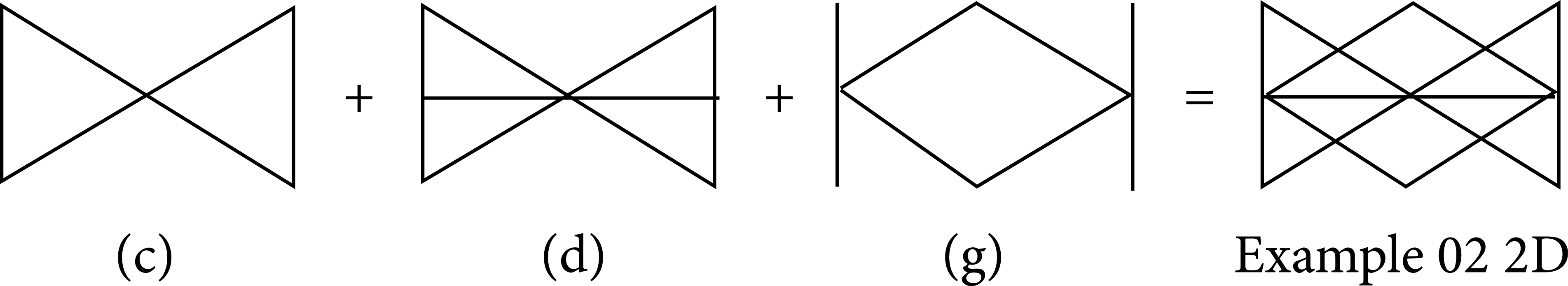
Example 02 2D topological design.
The results of the optimization for example 02 2D are presented in Figure 6. The left side shows the construction before optimization, and the right side shows the construction after optimization has been carried out. The boundary conditions and applied forces are presented. In the initial design, the stress distribution throughout the structure is unsteady. After the optimization process, the total number of elements is reduced to 76 and is further reduced to only 40. The topological design of the optimal construction is a multistage X frame structure, represented as design (c) in Figure 5. In the optimal design, the stress is equally distributed throughout the system.
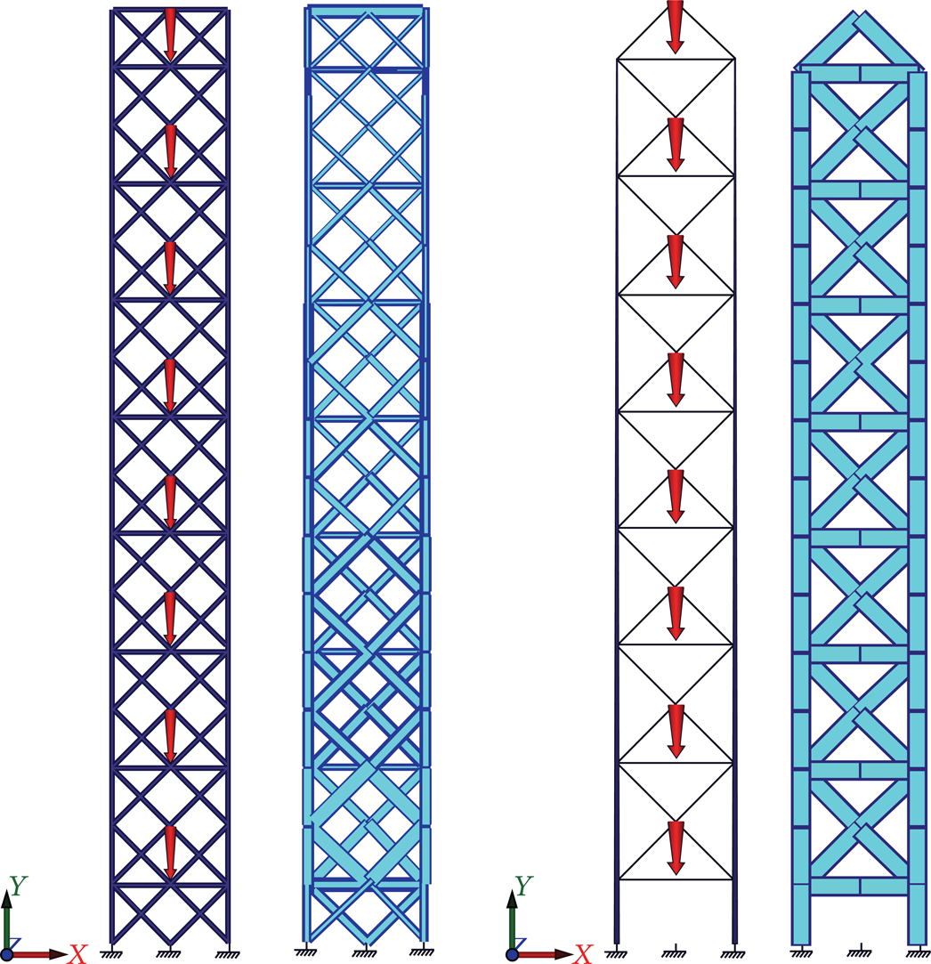
Example 02 2D optimization.
The initial design domain of example 03 for a 2D topological design is constructed from topological designs (c), (e), and (g) in Figure 1, as shown in Figure 7. In each storey, there is an X frame shape that is further stiffened by adding additional internal triangular placed bars. In the design, the deltoid placement of elements is also included, thus making the number of elements in each storey 22. As we construct an 8-storey truss, the total number of elements is increased to 178. Two horizontal bars are placed on top of the construction to close the shape.

Example 03 2D topological design.
Example 03 2D is a slender construction tower that narrows with increasing height. At the base, the width is 2 m, whereas, at the top, the width is reduced to only 1 m, making a 2° angle of inclination, as seen in Figure 8. The truss is subjected to eight compression loads and stands on three rigid bases. In the initial design, the stress distribution throughout the structure is uneven. After the optimization process, the total number of elements is reduced to 90 and the number can be further reduced to only 46 by subtracting the collinear beams. The topological design of the optimal construction is a multistage X frame structure, represented as design (c) in Figure 7. In the optimal design, the stress is equally distributed throughout the system.
Example 03 2D optimization.
The optimization process for 2D examples is shown in Figure 9. The horizontal axis shows the number of iterations to achieve the final optimum. The vertical axis shows the change in the volume compared with the initial volume. The number of iterations is large as expected because of the large and uniform initial cross-section size of the elements, as well as the small area alteration through iterations.

2D examples optimization process.
During the optimization process, the volume of the structures slowly decreases by changing the element cross-sections. After a number of iterations, the criteria for element removal delete unnecessary elements from the structure, shown as a clear step in the chart. After element removal is carried out, the area cross-section can be increased to satisfy the stress conditions.
In example 01 2D, the number of iterations was 404, and the volume was reduced by 81% from an initial value of V0,01,2D = 201108350,6 mm3 to the optimum value of Vopt,01,2D = 37766733,69 mm3. In example 02 2D, the optimum value was achieved after 392 iterations, and the volume was reduced by 79% from an initial value of V0,02,2D = 140509668 mm3 to the optimum value of Vopt,02,2D = 42084434,32 mm3. Example 03 2D shows a change in structural volume that resembles a two-stage optimization process. From this graph, it is clearly seen that the adopted algorithm is capable of carrying out simultaneous size and topology optimization process. After 704 iterations, the volume was reduced by 71%, from an initial of V0,03,2D = 129759420,1 mm3 to the optimum value of Vopt,03,2D = 56766556,93 mm3. In all three examples, the initial structural design was far from the optimal, and the process produced structures that can be further adapted into the construction process.
6.2. 3D Examples
Presented are several examples of a 3D truss made from straight members. All examples are constructed from eight equal stories with base dimensions of 2 × 2 × 2 m. The stories are several topological designs placed on the vertical planes, as explained further on, in each example. They all have horizontal bars connecting the internal structure. The structures are loaded with equal compressive loads in every storey. Four loads are implied in each storey and are placed on the highest node in every vertical plane. For better comprehension, the load positioning is shown for every example.
As a consequence of the equal initial cross-section area of the elements, the initial stress distribution is not uniform, and some structural elements may be understressed or overstressed. Throughout the optimization process, this stress distribution is evolving towards a uniform state, and the final optimum design forms an FSD structure. Throughout the optimization process, the area cross-sections change to fulfill the constraints, and, if needed, unnecessary elements are reduced from the design space.
In example 01 3D, the initial design domain presents a construction from topological designs (a), (c), (d), and (g) in Figure 1, as shown in Figure 10. There is a simple K frame design in each storey, as well as a basic X frame design, which is further stiffened with an additional horizontal bar. The deltoid placement of the horizontal bars is also presented, so the number of bars in each storey is 68. Because we construct an eight-storey structure, the total number of used elements increases to 544.

Example 01 3D topological design.
The optimization process of example 01 3D is presented in Figure 11. The left side shows the truss with the boundary conditions and applied forces. In the initial design, the stress distribution throughout the structure is uneven. After the optimization process, the total number of elements is reduced to 148 including the reduction of elements and the subtraction of collinear beams. In the optimal design, the stress is equally distributed throughout the system. The topological design of the optimal construction is a multistage K frame structure, represented as design (a) in Figure 10.

Example 01 3D optimization.
In example 02 3D, the initial design domain presents a construction from topological designs (a), (b), and (f) in Figure 1, as shown in Figure 12. There is a simple K frame design in each storey that is further stiffened with additional filling bars as well as a finer mesh shaped design. The number of bars in each storey is 102. Because we construct an eight-storey truss, the total number of used elements increases to 816.

Example 02 3D topological design.
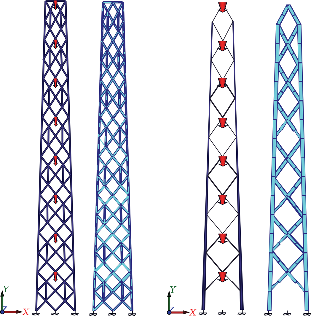
Example 02 3D is shown in Figure 13. The figure shows that the structure is becoming more slender as the structural height increases. At the base of the construction, the ground dimensions are 2 × 2 m, whereas, at the top, the dimensions are 1 × 1 m, making a 2° angle of inclination. The left side shows the truss with the boundary conditions and applied forces. The initial design shows that the stress distribution throughout the structure is uneven. After the optimization process, the total number of elements is reduced to 220 including the reduction of the elements and the subtraction of the collinear beams. The topological design of the optimal construction is a multistage K frame structure, represented as design (a) in Figure 12.

Example 02 3D optimization.
In example 03 3D, the initial design domain represents a construction from topological designs (c), (d), and (g) in Figure 1, as shown in Figure 14. There is a simple X frame design in each storey that is further stiffened with additional horizontal bars. The deltoid placement of the horizontal bars is also shown, and the number of bars in each storey is 52. Because we construct an eight-storey truss, the total number of elements increases to 424. Eight horizontal bars are placed on top of the construction to form a closed shape.

Example 03 3D topological design.
The initial design of Example 03 3D is seen in Figure 15. The left side shows the truss with the boundary conditions and applied forces. The initial design shows that the stress distribution throughout the structure is uneven. After the optimization process, the total number of elements is reduced to 182 including the reduction of the elements and the subtraction of the collinear beams. The topological design of the optimal construction is a multistage X frame structure with additional horizontal bars, represented as design (d) in Figure 14.

Example 03 3D optimization.
The number of iterations to achieve the optimal solution for the 3D examples is high because of the large and uniform initial cross-section size of the elements as well as the small area alteration through iterations. The initial designs of the structures are far from the desired optimum, as seen in the graph of the optimization process in Figure 16. The horizontal axis shows the number of iterations to achieve the final optimum. The vertical axis shows the change in the volume compared with the initial volume.

3D examples optimization process.
During the optimization process, the volume of the structures gradually decreases. Initially, only the cross-section area changes, because the element removal criteria cannot be fulfilled in the first steps because of the small iterative increment. A clear step is presented in the graph, showing the element removal process. In some cases, after area removal is carried out, the element cross-section can be increased. The process can be made faster by considering the initial cross-section sizes. It is not necessary that the initial area size be bigger than the optimum value for the algorithm to work.
In example 01 3D, the number of iterations is 644, and the volume is reduced by 79% from an initial value of V0,01,3D = 742401856,5 mm3 to the optimum value of Vopt,01,3D = 151674255,4 mm3. Example 02 3D shows that, after element removal has been carried out, the element cross-section has to be increased to satisfy all the constraints. The optimal construction is achieved after 889 iterations, and the volume is reduced by 63% from an initial value of V0,02,3D = 725126781,3 mm3 to the optimum value of Vopt,02 = 271989040,3 mm3. In example 03 3D, the optimum value is achieved after 661 iterations. The volume is reduced by 77% from an initial value of V0,03,3D = 543293506 mm3 to the optimum value of Vopt,03,3D = 168889913,2 mm3. In all three examples, the optimization process produces structures that can be further adapted into the construction process.
7. Conclusion
The main objective of this paper is to research the capabilities of the ESO algorithm to solve simultaneous size and topology optimization problems of truss structures constructed with straight members. Such types of structures are generally used for telecommunication and transmission towers, and their internal layout is usually a pregenerated shape. An efficient optimization algorithm to determine the internal structure would help designers make a better decision on the used internal topology.
In the research, several numerical examples for 2D and 3D structures of this type have been made, showing promising results. Therefore, we can conclude that this type of optimization procedure is very useful for solving the described problems. The procedure can be further adjusted for tower optimization with the implementation of stability checking algorithms in the optimization loop.
The research was conducted using the ESO optimization technique. Therefore, the initial internal structure represented the optimum design space. Using the iterative procedure, unwanted material was removed or added from the elements, and, furthermore, elements were removed if they do not satisfy the conditions. Once removed, an element could not be returned to the design domain. Further research can be conducted using a sort of adapted BESO method to allow element inclusion in the design space. This procedure is complex since only beam types of elements are being used, and the inclusion criteria should be selected with regard to the behavior change of the structure.
Conflict of Interests
The authors declare that there is no conflict of interests regarding the publication of this paper.