
Abstract
We present a low cost battery-powered 6-degree-of-freedom wireless wand for 3D modeling in free space by tri-axis Magnetic, Angular Rate, Gravity (MARG) and vision sensor fusion. Our approach has two stages of sensor fusion, each with different algorithms for finding 3D orientation and position. The first stage fusion algorithm, a complementary filter, utilizes MARG sensors to compute 3D orientation relative to the direction of gravity and earth's magnetic field in a quaternion format, which was adjusted with compensations for magnetic distortion. The second stage fusion algorithm, a Kalman filter, utilizes accelerometer data and IR marker velocity to compute 3D position. In order to compute the IR marker linear velocity along the optical axis (the z-axis), we present a simple and efficient image-based technique to find the distance of the object from the camera using blob area pixels in the image. Our fusion (inside-in and outside-in) approach efficiently solves short time occlusion, needs of frequent calibration, and unbounded drift problems involved in numerical integration of inertial sensors data and improves the degrees of freedom at low cost without compromising accuracy. The results are compared with a leading commercial magnetic motion tracking system to demonstrate the performance of the wand.
1. Introduction
There has been increasing research over the last decade in using 6DOF motion tracking devices for 3D spatial sketching and modeling [1–4] in immersive virtual reality (VR) environments. Other efforts include 2D tablet screens used to draw a 2D sketch that is processed into 3D designs [5, 6]. The objective of practical spatial drawing and editing in 3D demands low-cost, precision, small size, and ease of use. Existing professional motion tracking systems that use electromagnetic, ultrasonic, optical, inertial, and multiple-sensor technologies [7] are too expensive for commercial 3D immersive VR and modeling and require a degree of technical knowledge to use them. Outside-in stereo vision has been widely used for 3D modeling, but this system often suffers from occlusion and interference and apparent loss of DOF. Any accidental change in the position of a camera after calibration requires complete recalibration [8].
3D motion-based human computer interaction (HCI) has long been an active research topic in VR, and it has been shown that 3D interfaces can be useful in many consumer-level applications such as home gaming [9] and 3D user input [10–12]. Emerging demands for rich interaction have led to the development of handheld pointing motion interface devices [13, 14]. These commercial devices incorporate micro-electro-mechanical system (MEMS) inertial sensors such as accelerometers and gyroscopes, and their contributions are limited to gesture recognition, rotation, and vision sensing as for 3D position. These devices are aimed to interact with 3D digital media content and motion gaming and are unsuitable for 3D modeling and editing in free space, which requires precise 6DOF motion sensing.
The main technological bottleneck that limits accuracy in computing position and orientation from MEMS inertial sensors is the drift caused by numerical integration of acceleration and angular rate [15–17]. However, inertial sensors are well known for their short term precision, high-frequency data rates, and size. To leverage these advantages, benefits of sensor fusion techniques using additional sensors have been proposed by researchers in the areas of navigation [18, 19] and motion capture [20].
Another recent innovative work, called MEMSEye, uses MEMS-mirror-based optical 3D tracking [21]. Combination of two or more MEMSEye units can track light sources such as IR light-emitting diodes (LED) and corner cube retroreflectors (CCRs). By triangulating the tracked object's relative position from each unit, its 3D position can be computed in relatively large volumes with submillimeter precision at update rates of >20 kHz. However, a fully functional unit using this technology platform costs more than one thousand dollars, making it unaffordable for a wide range of users.
With increasing interest in 3D display devices, a simple and low-cost solution that can provide enough precision and flexibility is not yet available for 3D modeling. Our work aims to advance 6DOF motion sensing by two-stage multisensor (MARG and vision) fusion to make use of their complementary properties, which was inspired by multisensor navigation systems. So it is essential to acquire accurate timestamp information to synchronize MARG measurements and the camera. In order to do that, we use a hardware triggerable IR camera.
This paper is organized as follows. Section 2 gives the description of the proposed system design and the details of the wireless wand architecture. Section 3 explains first stage sensor fusion for 3D orientation using MARG sensors and the magnetic distortion correction technique. In order to find the linear velocity of the IR marker along the camera z-axis, we explain our image-based technique in Section 4, followed by a description of the second stage sensor fusion, and performance comparison results with a leading commercial motion tracking system in Sections 5 and 6, respectively. Section 7 concludes our approach. Throughout the paper, a notation system of leading superscripts and subscripts similar to [22] is used to denote the relative frame of orientations and vectors. For example,
2. System Design
2.1. System Overview
The wireless wand is designed to be used in front of a computer monitor with a camera attached on top of it as shown in Figure 1(a). We use a wide field of view camera which has an IR filter and

System setup to work with wireless wand; (a) working volume of wand in front of camera and different frame of references involved; (b) wand.

Data packet and API: (a) data packet format sent from wand; (b) API to communicate and process data from the wand and camera.
2.2. Wand Architecture
The wand shown in Figure 1(b) has a triaxis digital 16-bit gyroscope, 12-bit accelerometer, and 12-bit magnetometer, each with its own respective selectable ranges of up to ±2000°/s, ±8 g, and

Wand architecture.
3. MARG Sensor Fusion for 3D Orientation
To compute drift-free measurement of 3D orientation relative to the direction of gravity and earth's magnetic field, researchers proposed several algorithms using MARG sensors [23–26], also known as an attitude heading reference system (AHRS). A complementary filter using low-cost MEMS inertial measurement unit (IMU) with magnetometer was proposed [23] with deep mathematical basis to compute 3D orientation in a direction cosine matrix (DCM) and quaternion form [24]. Though this algorithm showed how a magnetometer can be used along with an IMU (gyroscope and accelerometer) to compute 3D orientation relative to the earth direction of gravity and magnetic field, it was not able to correct drift as was intended due to lack of a compensation technique for magnetic distortions resulting from nearby sources such as metal structures or power supply buses. Several investigations [25, 27] have shown that substantial errors may be introduced by magnetic distortions in orientation estimated from MARG sensors. By adapting a technique proposed in [22] for compensating for magnetic distortions (termed soft iron errors), a complementary filter algorithm in quaternion form has been implemented on a low-power hardware board in the wand system.
The potential advantage of this algorithm is in correcting drift in orientation computed from gyroscope measurements using an additional reference orientation computed from the accelerometer and magnetometer, by successfully incorporating magnetic distortion compensation without any singularity problems. One more key advantage of this technique is that it eliminates the need for the direction of earth's magnetic field to be predefined, which has been a potential disadvantage of other algorithms [25, 26]. The block diagram shown in Figure 4 represents the first stage sensor fusion AHRS algorithm, in which red color box indicates the magnetic distortion compensation technique. More details of the algorithm are given in the Appendix. The compensation technique is described as follows:


where

Complementary filter block diagram.
4. IR Marker Velocity Tracking
In order to compensate for the numerical drift that results from double integration of acceleration measurements of triaxis accelerometer, we compute 3D velocity of the IR marker from the output of a blob tracking module, which provides the width, height, area, and 2D position

where
Finding the distance of a specific-shaped object using a single image has been proposed in [28, 29]. Object's height in a thresholded binary image has been used to determine its distance from the camera using rectangular, triangular, cylindrical, and spherical shaped objects. However, object's size was relatively large, with minimum diameter of 0.65 m for a spherical object. For our experiment, we used an industry-standard IR camera with uniform radiation capability to illuminate a retroreflective spherical marker with 0.01 m diameter. Figure 5 shows the experimental setup used to determine how the IR marker object height and area pixels in the image change with varying distance from the optical center of the camera in the z- and x- axes. Initially, the marker is positioned exactly at the optical center of the camera and is moved away from the camera on a 2-axis linear rail system.

Experimental setup to observe object height and area.
It is found that the object height and area decrease exponentially with increasing distance (0.36 m to 1.5 m) from the camera along the z-axis, as shown in Figures 6(a) and 6(b), respectively. But, from Figure 6(a), it is clear that the object height does not change continuously with increasing distance when compared to the area of the object; this is the main reason for not using methods presented in other previous schemes [29]. It is also observed that the area measurements are repeatable at any particular intensity, exposure, and threshold settings of the camera. However, in order to calculate linear velocity, it is essential to linearize


Figure 6(b) is done by taking the logarithm. Analysis of Figure 6(c) leads to the fact that the object depth has a direct relationship with its logarithmic pixel area. Now, we can find the best fitting linear polynomial by linear regression to find the object distance to the camera, which is given in (5), where d is object distance and a is the object area in pixels. Having object distance, we can find the velocity along z-axis using (6), where k is a constant (scaling factor) determined by observation to get velocity in m/s units.

Object height and area with increasing distance from camera.
However, at a particular distance from the camera, when the marker moves laterally to the camera (perpendicular to optical axis) from camera center in either x- or y-axis direction, the object shape in image loses circularity, and the object area is not constant; it varies as shown in Figure 7. This significantly affects the velocity

Object area at different depth when object moved laterally to camera from its center.
The inertial navigation module shown in Figure 10 computes position and velocity estimates using translational accelerations and corrections obtained from a KF algorithm. The estimated z-axis velocity from this module,


observing

Before and after correction of c v z : (a) error introduced in c v z when marker moved along x-axis; (d) after correcting error in c v z ; (c) error introduced in c v z when marker moved along y-axis; (e) after correcting error in c v z .
5. Sensor Fusion for 3D Position
The MEMS triaxis accelerometer measures acceleration of the wand in the body (moving) frame of reference
5.1. Gravity Removal in Acceleration
A conditional offset filter [14] to remove gravity from acceleration may be sufficient when its output is used only for gesture recognition, but is not optimal in terms of responsiveness (depends on past data) and accuracy (gravity still persists in transition regions). This affects accuracy when our interest is precise position computation from translational acceleration. The following method, using a quaternion

Gravity removal in acceleration: (a) acceleration; (b) gravity vector computed; (c) resulting translational acceleration after gravity removed.

Combined tracking.
Consider the following:


5.2. Combined Tracking
A block diagram of combined tracking is shown in Figure 10 which serves as second stage sensor fusion algorithm. A 9-state Kalman filter incorporated is the heart of this algorithm. The KF is an efficient recursive filter algorithm that provides optimal estimates of system states from noisy observation data given the underlying model of the system and assumes all the errors and measurements have zero mean white Gaussian noise. It is also well known that to compensate for errors of inertial navigation systems, inertial sensors have to be assisted by other sensors, and use of a KF is common for fusing data from different sensors. Also KF is used in different applications, for example, moving target tracking in a video [31]. We propose fusion of high sampling rate MARG sensors and low frame rate vision sensor in second stage sensor fusion for 3D position tracking, which benefits from their complementary characteristics. The state variables of the KF are position, velocity, and translational acceleration.
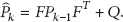
The inertial navigation computing module estimates position and velocity from translational acceleration vector

Time Update. The state estimate and error covariance are propagated based on the optimal estimation at previous time step
Consider the following:

For (15) we use estimates of inertial navigation computing task and optimal states at the previous time step

Matrices of size
Measurement Update. If measurements are available, this step incorporates those measurements in vector
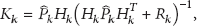


Measures of
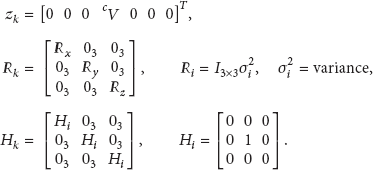
Since MARG sensors are sampled at 120 Hz and the camera is sampled at 75 FPS (<MARG sensors data rate), during each time step, we check the inertial navigation computing module for estimates and marker velocity vector
6. Results
The proposed tracking system was tested against a leading commercial DC magnetic tracking system at 120 Hz. To do so, we set the update rate of the proposed tracking system at 120 Hz and the camera FPS at 75 and fixed them to a rigid platform to be moved by hand. The trajectories of translational motion obtained from both the systems along x-, y-, and z-axes are plotted in Figures 11(a), 11(b), and 11(c), respectively. Comparison shows the potential of our system in both static and dynamic arbitrary movements. A close inspection of Figure 11(c) also reveals the linearity and accuracy of measurements obtained from (5), (6), and (7). This shows that our simple and efficient idea presented in Section 4 can find the marker velocity along the camera z-axis using area pixels of IR marker in thresholded image, without the need for another camera or additional markers to track the 3D position of the object.

Comparison of trajectories of translational motion obtained from commercial tracker with our wand.
In order to compare the quaternion orientation data of the two systems, orientation with respect to their fixed, steady state quaternions were measured and then decoupled to Euler parameters describing the pitch φ, roll θ, and heading ψ corresponding to rotations around the body frame x-, y-, and z-axes, respectively. Figure 12 shows plots of 3D orientation obtained from the wands complementary filter for which magnetic distortion compensation incorporated. To show the performance of our wand, comparison of the 3D trajectories for helical motion in the earth frame of reference is presented in Figure 13.

Comparison of Euler angles computed from quaternion orientations obtained from commercial tracker with our wand.

Comparison of 3D trajectories obtained from wand with commercial tracker.
7. Conclusion
Motion tracking using MARG sensors with additional sensors is a mature field of research. Modern techniques [14–16] have focused on simpler fusion approaches on low power hardware to reach a wide range of users. We presented a simple and accurate approach for a wand system with two stage sensor fusion: the first stage of fusion offloads the 3D orientation computation from the computer, allowing focus on only 3D position computation in the computer as the camera is connected to it. The basic idea is to utilize low cost and wide field of view USB camera with IR filter to prevent numerical drift in the position computed from the acceleration of a MEMS accelerometer. Thus the overall system benefits from the complementary properties of inertial and vision sensing. Key advantages of the proposed system are (1) the working area of device, which allows user to interact with a computer or 3D TV at a comfortable distance by changing size of IR marker; (2) the small size and higher update rate; (3) the magnetic distortion compensation that helps to use the wand in challenging environments; and (4) another potential application of this device that includes air digital writing and signature verification.
Footnotes
Appendix
Conflict of Interests
The authors declare that there is no conflict of interests regarding the publication of this paper.
Acknowledgment
This research was supported by the Chung-Ang University Research Scholarship Grants in 2011.