
Abstract
This paper presents a failure analysis on a modern high performance diesel engine cylinder head made of gray cast iron. Cracks appeared intensively at the intersection of two exhaust passages in the cylinder head. The metallurgical examination was conducted in the crack origin zone and other zones. Meanwhile, the load state of the failure part of the cylinder head was determined through the Finite Element Analysis. The results showed that both the point of the maximum temperature and the point of the maximum thermal-mechanical coupling stress were not in the crack position. The excessive load was not the main cause of the failure. The large cooling rate in the casting process created an abnormal graphite zone that existed below the surface of the exhaust passage (about 1.1 mm depth), which led to the fracture of the cylinder head. In the fractured area, there were a large number of casting defects (dip sand, voids, etc.) and inferior graphite structure (type D, type E) which caused stress concentration. Moreover, high temperature gas entered the cracks, which caused material corrosion, material oxidization, and crack propagation. Finally, premature fracture of the cylinder head took place.
1. Introduction
In the durability assessment test of a V-shaped 8-cylinder diesel engine which had been strengthened, the cracking failure of the cylinder head occurred frequently. Compared with the prototype diesel engine (the rated speed is 2100 r/min, the cylinder diameter is 132 mm, and the single-cylinder power is 55 kW), the rated speed of the improved diesel engine reaches 2500 r/min and the single-cylinder power is up to 92 kW. The arrangement of the cylinder head in this diesel engine is stand-alone (A cylinder head corresponds to a cylinder), and the material of the failed cylinder head is gray cast iron (HT250) which is mainly composed of iron matrix and flake graphite.
In this paper, a detailed metallurgical investigation and a fractographic observation on the failed cylinder head were conducted. The load state of the failure part of the cylinder head was determined through the Finite Element Analysis. Finally, the possible failure causes were assessed.
2. Failure Description of the Cylinder Head
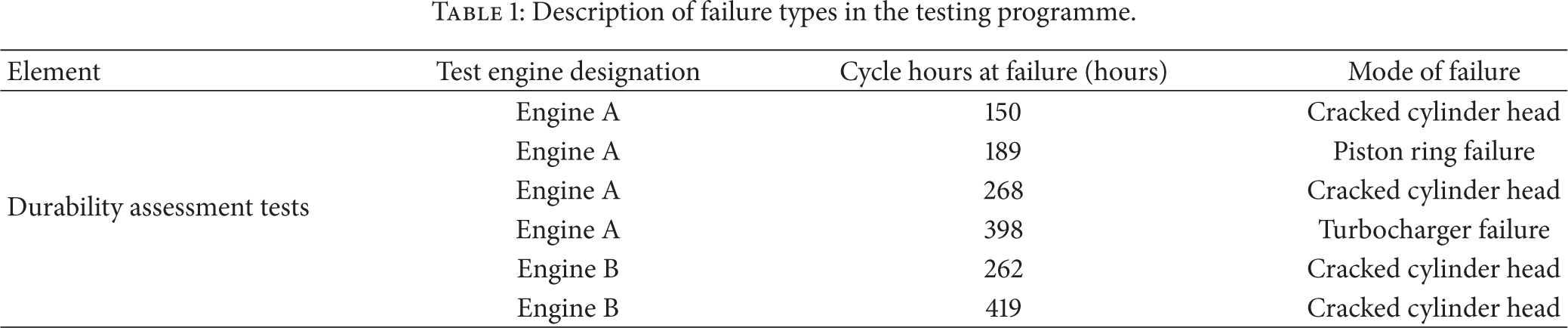
Each cylinder of the diesel engine has four valves (two intake valves, two exhaust valves). During the durability assessment test, the unexpected cracking failure of the cylinder head happened frequently. Details of the failures and times of occurrence are given in Table 1. The cracking situation of the cylinder head was shown in Figure 1. Cracks appeared intensively at the intersection of two exhaust passages in the cylinder head and extended to cooling watercourse from the surface to the depth direction, which made the coolant leak and even led to the failure of the cylinder head.
Description of failure types in the testing programme.

Failed cylinder head.
3. Fracture Surface Investigation
3.1. Optical Inspection and Stereomicroscopy
The sample was taken from the crack position on the cylinder head of the engine and washed by acetone solvent with ultrasonic wave, and the observation on the surface was conducted by stereoscopic microscope. The result (the cracking trace) was shown in Figure 2.
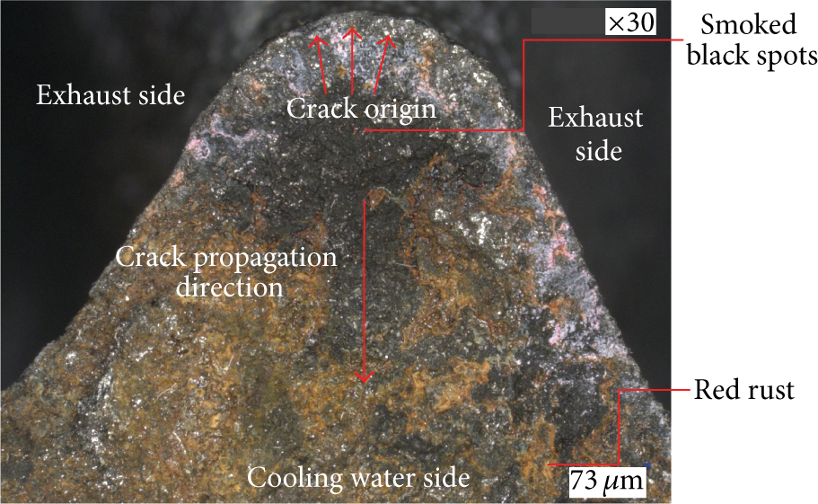
The cracking trace.
From a macropoint of view, the fracture surface was relatively flat and contained a lot of oxides. Cracks in the exhaust side contained black smoke stains which were generated by the engine exhaust, since it deposed and infiltrated into the crack surface for a period of time. The fracture zone embodied the characteristics of the fatigue crack propagation. According to the trace of the crack, it could be conducted that the cracking source was initiated at the intersection of two exhaust passages, and then it grew and deepened along the surface and extended to the cooling watercourse.
3.2. Microstructure
The microstructure observations on the samples taken from the fractured end were conducted by microscope and scanning electron microscope (SEM). The microstructure was evaluated according to the Chinese standard [1], and the result was shown in Figure 3. From Figure 3, it could be concluded that in most zones, the microstructure was composed of the flake graphite (type A) [1, 2], fine pearlite, and a small amount of ferrite. However, the length of the graphite plate was over the specified range.

Typical microstructure of the cylinder head material: (a) low magnification; (b) high magnification.
Most importantly, as shown in Figure 4 (the crack region), the abnormal graphite zone (about 1.1 mm depth) was found below the exhaust passage surface. It was shown in Figure 5 that type A graphite (homogeneous distribution) and type B graphite (aggregate of chrysanthemum-shaped, small, and curled graphitic flakes) coexisted in the area beyond the depth of 1.1 mm, while Figure 6 indicated that type D graphite (the small and curled graphitic flakes in interdendritic spaces distributed with no direction) and type E graphite (the small and curled graphitic flakes between dendrite secondary branches distributed directionally) coexisted in the abnormal graphite zone within the depth of 1.1 mm. Usually type D and type E graphite were formed with large cooling rate of liquid iron in the casting process. Therefore, in the exhaust side, the existence of type D and type E graphite in array resulted from the large cooling rate, and it was easy to initiate crack under the mechanic load and thermal load.

Abnormal graphite zone near the crack origin region.

Microstructure of the normal graphite: (a) low magnification; (b) high magnification.

Microstructure of the abnormal graphite: (a) low magnification; (b) high magnification.
Meanwhile, as shown in Figure 7, near the main crack of the exhaust side, another two cracks were found, which came from the casting process. Two cracks were derived from casting defects. Crack A with the length of 300 μm propagated along the tiny graphitic flakes in array, and oxide existed in the crack (Figure 7(a)). Crack B with the length of 4.2 mm was initiated from the burnt-on sand in the surface and propagated along the flake graphite which arrayed with crystal in the austenite dendrite (Figure 7(b)). The tip of the crack B was oxidized with the 10 μm oxidized layer, and much oxide existed in the crack (Figure 8). The expansion of oxide and the oxidized erosion in the crack tip furthered the crack propagation [3]. In addition, as shown in Figure 9, the amount of casting defects with large size was observed near the origin place of the crack. Obviously, if this casting material worked under a thermal-mechanical load, these defects would generate a high concentration stress, which would promote microcracks propagation. As a result, the cylinder head would fracture prematurely.
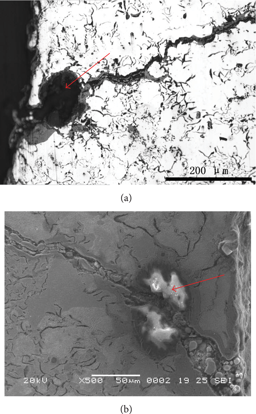
Two cracks are derived from casting defects: (a) voids; (b) dip sand.
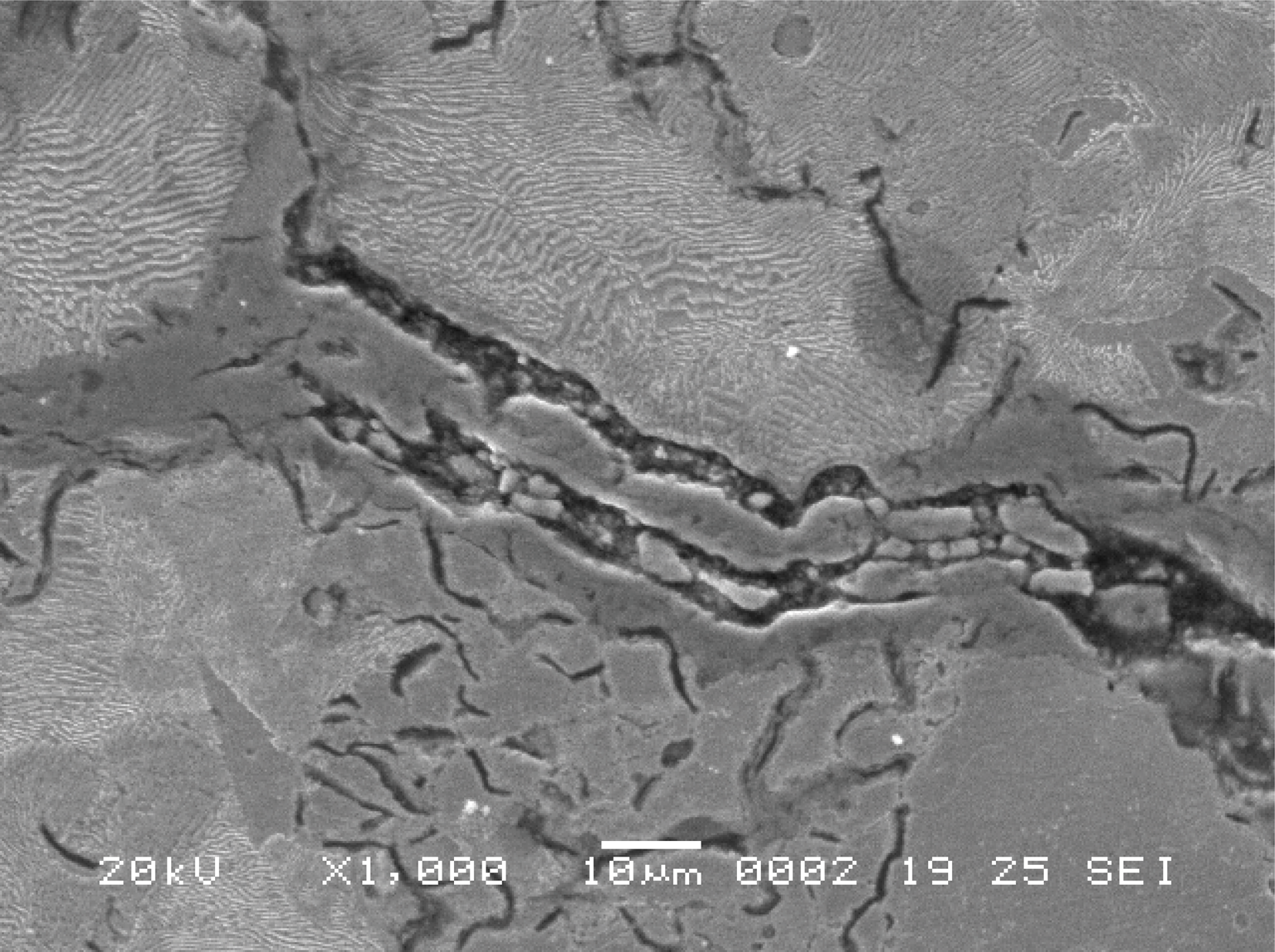
Oxide existing in the crack.

Casting defects.
3.3. Chemical Composition of the Cylinder Head Material
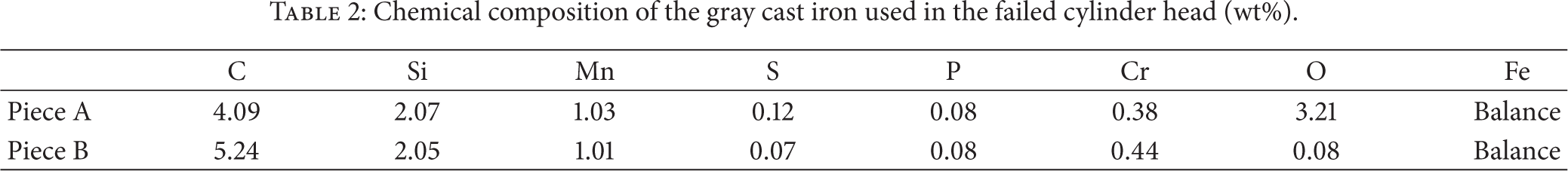
The chemical composition of the failed cylinder head material was determined by spectroscopy chemical analysis method. The results were shown in Table 2. Piece A was taken from the abnormal graphite zone which is nearby the source of the crack and about 1.1 mm far from the exhaust duct, while piece B was taken from the normal graphite zone. It can be seen that the proportion of C (carbon) in the abnormal graphite zone was lower than in the normal graphite zone, but other elements (except oxygen) like Si in these two zones roughly had the same proportion. In addition, compared with piece B, piece A contained more O (oxygen), which might be induced by oxidation of the microcracks on the surface.
Chemical composition of the gray cast iron used in the failed cylinder head (wt%).
4. Discussion of Cause and Prevention
4.1. The Load Analysis of the Cracking Parts
Temperature and stress in the crack position of the failure cylinder head were determined with Finite Element Analysis. A finite element model of the cylinder head is constructed, as shown in Figure 10. The finite element model has 157868 elements and 253966 nodes. The assembled finite element model, including cylinder head, cylinder bolts, cylinder sleeve, gasket, and engine block, is constructed in order to precisely simulate the real contact and loading conditions in the stress analysis, as shown in Figure 11. Contact condition is assigned to the interfaces between components. A friction coefficient of 0.15 is defined to the contact surface between cylinder head and gasket.
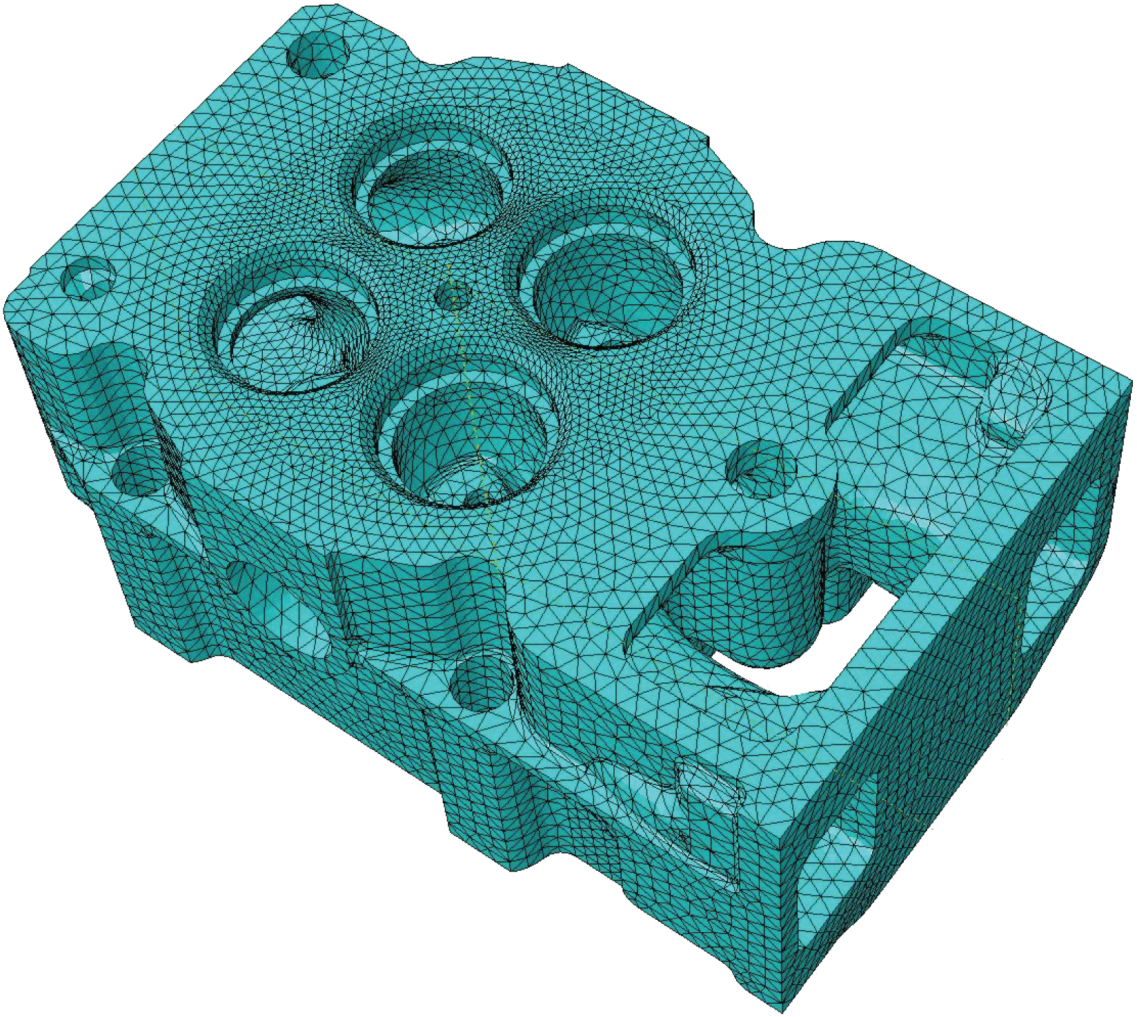
Finite element model of the cylinder head.

The assembled finite element model.
With steady state thermal analysis, the temperature field of diesel engine cylinder head was obtained based on ABAQUS software. As shown in Figure 12, a partial high temperature area appeared at the intersection of the two exhaust passages in the cylinder head where there existed the highest temperature (381.6°C). However, the highest temperature did not occur at the cracking location (Figure 12).

Temperature field: (a) a sectional view; (b) exhaust crossing.
Based on the temperature field which had been obtained above, the explosion pressure and the bolt pretightening force were considered in the further analysis. The result was shown in Figure 13 which was the thermal and mechanical coupling stress (von Mises stress) diagram at the cracking parts of the cylinder head. From Figure 13, it could be seen that a local high stress area (the maximum pressure is 273.9 MPa, a compressive stress) existed at the intersection of the two exhaust ducts. However, just like the temperature distribution shown in Figure 12, the maximum pressure also did not appear in the crack position.

Thermal-mechanical coupling stress field.
4.2. Compression Properties of Material of the Cylinder Head
The crush tests of gray cast iron (with normal graphite morphology) were conducted to obtain the compressive properties of the material of the cylinder head under different temperatures. As shown in Figure 14, compressive stress-strain curves at 20°C, 400°C, and 500°C were obtained. The compressive yield limit was about 500 MPa at 400°C, which was far greater than the thermal and mechanical coupling stress (273.9 MPa). Thus, under normal circumstances, the junction of the exhaust passages had a high safety factor, which meant that it would not crack.
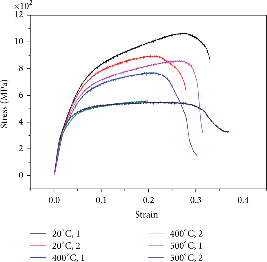
The compressive stress-strain curve of the material.
4.3. Analysis on the Failure Causes and Prevention of Future Failures
From the results in Sections 2–4, it could be inferred that compared with the specified one, the length of the graphite was generally longer. However, this defect would not lead to the premature fracture of the cylinder head [2, 4]. The Finite Element Analysis results showed that, at the junction of exhaust ducts, both the point of the maximum temperature and the point of the maximum stress were not in the crack position. At the crack position, the load on the material was lower than the compression yield strength with the same temperature, which meant that the high load was not the main reason that caused the failure of the cylinder head. The large cooling rate in the casting process created an abnormal graphite zone that existed below the exhaust passage surface (about 1.1 mm depth), which led to the fracture of the cylinder head. In this area, there was a large number of casting defects (dip sand, voids, etc.) which caused the stress concentration points. Therefore, fatigue cracks were initiated in this region more easily. High temperature gas among cracks caused corrosion or oxidation furthering the crack propagation. The crack was initiated from the exhaust passage surface of the cylinder head and propagated toward the edge of the cylinder head under the mechanical and thermal load.
Based on the above reasons, the next generation of modern high performance diesel needed new technologies to improve the cylinder head components. On one hand, a new casting technology should be applied to avoid abnormal graphite morphology and the casting defects resulting from excessive cooling rate and uneven cooling at the exhaust surface, and then the quality of the material used on the exhaust ducts could be improved. On the other hand, a technical requirement of the casting cylinder head needed to be reenacted, which meant that a new standard of the acceptance to the quality of the surface at the intersection of two exhaust passages in the cylinder head at casting process should be adopted.
5. Conclusions
In order to analyze the failure causes of a modern high performance diesel cylinder head, the detailed metallurgical investigation and the fractographic observation on the failed cylinder head were conducted. The load state of the failure part of the cylinder head was determined through the Finite Element Analysis, and then the possible failure causes were assessed. The following conclusions were drawn.
The crack was initiated from the exhaust passage surface of the cylinder head and propagated toward the edge of the cylinder head under the mechanical and thermal load.
The Finite Element Analysis results showed that the leading crack did not go through the highest temperature area and the highest stress area. So the excessive load was not the main cause of the failure.
The large cooling rate in the casting process created an abnormal graphite zone that existed below the exhaust passage surface (about 1.1 mm depth), which led to the fracture of the cylinder head. In this area, there were a large number of casting defects (dip sand, voids, etc.) which caused stress concentration points. Therefore, it was easier for the fatigue cracks to be initiated in this region.
High temperature gas entered the cracks and caused corrosion and oxidation, which furthered the crack propagation.
Conflict of Interests
The authors declare that there is no conflict of interests regarding the publication of this paper.