
Abstract
The electromechanical coupled forced response of the microplate subjected to electrostatic force is investigated. Using electromechanical coupled dynamic equations and the mode superposition method, the forced responses of the microplate to voltage excitation and load excitation are analyzed, respectively. Based on this, the coupled forced responses of the micrplate to voltage and load excitations are obtained. Beat vibration caused by the coupled response is investigated and the condition that the beat vibration occurs is determined.
1. Introduction
MEMS are the integrated system consisting of microelectronics, microactuators, and microsensors. For more than a decade, research on MEMS has been conducted by almost all major universities and research institutions [1–3].
A typical MEMS structure consists of thin beams with cross-sections in the order of microns and lengths in the order of ten to hundreds of microns. Sometimes, MEMS elements are thin plates or thin rings. An example is a small rectangular silicon plate with sides in the order of mm and thickness of the order of microns that deforms when subjected to electric field force. Examples of devices that utilize vibrations of such plates are synthetic microjets, microspeakers, and so forth [4]. Another example is micromechanical gyroscopes which are exclusively of vibrating types, including double-gimbals structure, cantilever beam structure, tuning-fork structure, and vibrating ring structure [5–7].
Understanding the dynamic behavior of MEMS is very important for developing new MEMS devices and controlling their performance. Nadal-Guardia et al. used one-dimensional lumped model of parallel plate electrostatic transducers and studied its dynamic behavior [8]. The authors presented an electromechanical coupled dynamic model of the microbeam subjected to electrostatic force [9]. Zhang et al. investigated the bending, buckling, and vibrations of micro/nanobeams with the hybrid nonlocal Euler-Bernoulli beam model [10]. Sedighi and Shirazi presented a new asymptotic procedure to predict the nonlinear vibration behavior of microbeams predeformed by an electric field [11]. Shabani et al. investigated the free vibrations of a cantilever microbeam submerged in a bounded frictionless and incompressible fluid cavity [12].
The microplate is a key element of MEMS system. The electromechanical coupled forced response of the microplate to different excitations has important effects on the operating performance of the MEMS system and should be investigated.
In this paper, the electromechanical coupled forced response of the microplate subjected to electrostatic force is investigated. The coupled forced responses of the microplate to voltage and load excitations are obtained. Beat vibration caused by the coupled response is found and the condition that the beat vibration occurs is determined. The results are useful in designing and manufacturing of the MEMS.
2. Calculating Methods
2.1. Electromechanical Coupled Dynamics
Figure 1 illustrates an electromechanical coupled dynamic model of a microplate subjected to electrostatic force. The dynamic equation of the microplate is
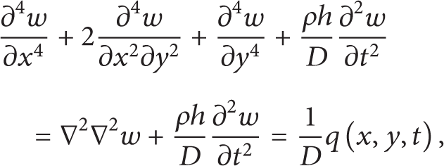
where w(x,y,t) is transverse displacement of the microplate, x is length coordinate of the microplate, y is the width coordinate of the microplate, t is the time, ρ is material density per unit area of the plate, h is the thickness of microplate, D is bending stiffness of the plate, q(x,y,t) is electrostatic force per unit area of the plate, D = Eh3/12(1 − μ2), here, E is modulus of elasticity of the microplate material, and μ is Poisson's ratio of the microplate material.

Electromechanical coupled dynamic model of a microplate.
The electrical field force F e between two plates can be given:

where v is the voltage, C is the capacitance between the microplate and base plate, C = (ε0A/((t0 − w + d c )/ε r )), ε0 is permittivity constant of free space, ε0 = 8.85 × 10⁻¹² C2·N−1·m−2, ε r is relative dielectric constant of the insulating layer, t0 is initial clearance between microplate and base plate, d c is the thickness of the insulating layer, A is effective area between the microplate and base plate, A = ab, a is length of the microplate, and b is its width.
From (2), the electrostatic force q(x,y,t) per unit area between the microplate and base plate can be calculated as below:

The total displacement w of the microplate consists of the static displacement w0 and the dynamic displacement Δw:

Change of the displacement results in change of the capacitance, voltage, electrostatic force, and quantity between microplate, and base plate. Thus,


where C0 and ΔC are the static capacitance and the dynamic one, respectively; v0 and Δv are the static voltage and the dynamic one, respectively; F0 and ΔF are the static electrostatic force and the dynamic one, respectively; q0 and Δq are its static component and the dynamic one, respectively.
Differentiating (5a) with respect to distance w gives

Substituting (5a) and (6) into (2), neglecting higher order terms, yields


The dynamic electric field force includes two terms. The first term is

It includes Δw and has effect on the natural frequency of the microplate. So, it is remained in the free vibration equation.
The second term does not include Δw and includes Δv. It has no effect on the natural frequency of the microplate. It is an exciting force to the microplate. So, it is considered in the forced responses of the microplate to the voltage excitation.
Substituting (4) and (5d) into (1), neglecting higher order terms, yields

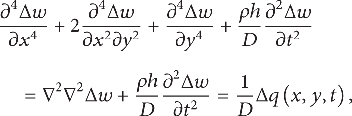
where
Equation (11) is linear electromechanical coupled dynamic equation of the microplate subjected to electric field force. Equation (10) is electromechanical coupled static balance equations of the microplate subjected to electric field force.
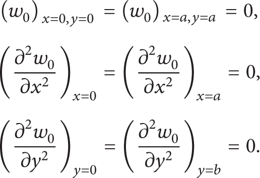
For the simply supported plate at four sides, the boundary conditions are
Substituting

Letting Δw = ΔW(x,y)q(t), substituting it into (13), yields

where
The mode function of the microplate is considered as

where A is a coefficient.
Substituting (15) into (14), the natural frequencies of the electromechanical coupled microplate system can be given:
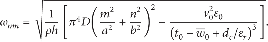
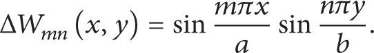
Letting A = 1, the mode function (15) can be changed into the following form:
2.2. Forced Response to Voltage Excitation
From (8), it is known that under variable voltage, the dynamic electrical field force will be caused and it is

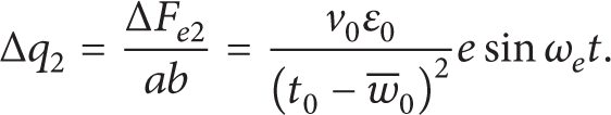
Letting periodic exciting voltage Δv = esinω e t (here, ω e is the exciting frequency of the voltage and e is the amplitude of the exciting voltage), substituting it into (18), the exciting electrical field force Δq2 per unit area is given:
The dynamic vibrating displacements of the microplate can be given as

where
Substituting (19) and (20) into (11) yields

where P mn (t) and M mn are generalized force and generalized mass, respectively,

Here, the initial condition is taken as zero, a mn = b mn = 0. Then, the above equation is simplified as
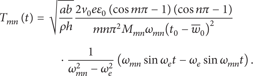
In (23), the forced response and associated free vibration are included. The associated free vibration will vanish soon under damping. Therefore, this item can be removed. Then, (23) is simplified as
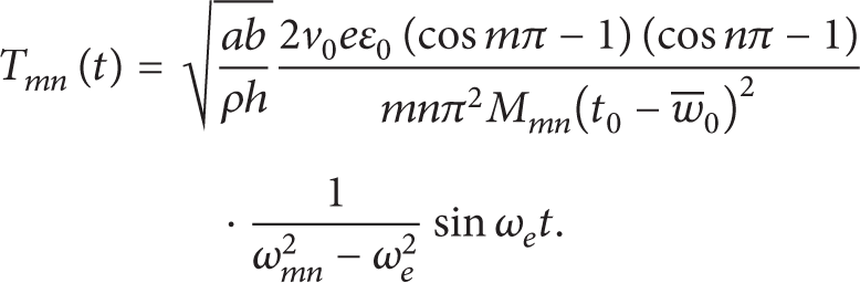
Combining (24) with (20), the forced response of the microplate to voltage excitation can be obtained.
2.3. Coupled Forced Response to Load and Voltage Excitations
When a variable load is applied to the microplate subject to electrostatic force, the forced response of the microplate to the load excitation will occur as well. Let

where qf0 and ω f are the amplitude and frequency of the exciting load, respectively.
Substituting (25) and (20) into (11) yields

In (26), the associated free vibration will vanish soon under action of the damp. Therefore, this item can be removed as well. Then, (26) is simplified as

Combining (27) with (20), the forced response of the microplate to load excitation is obtained.
When the variable load and the exciting voltage are applied to the microplate simultaneously, the coupled forced response of the microplate to the load and voltage excitations will occur. Letting the exciting load and voltage change periodically, that is, Δv is = esinω e t and Δq f = qf0sin(ω f t + φ), the exciting force per unit area can be given:

where φ is the phase difference between the load and voltage excitations.
Substituting (28) and (20) into (11), and neglecting associated free vibration item, yields

where
Combining (29) with (20), the coupled forced response of the micro plate to load and voltage excitations can be obtained.
When the phase difference between the load and voltage excitations is taken as zero (φ = 0), (29) can be simplified as

where

Equation (30) can be changed into the following form:

When θ = ψ and (32) can be changed into the following form:

From (33), it can be known that a kind of the special coupled vibration, that is, beat, will occur. The condition that the beat occurs is
3. Results and Discussion
Assuming that the microplate subjected to electric field force has the data in Table 1, using (16) and (17), the natural frequencies and vibration modes of the microplate are obtained. Here, voltage v0 = 2 V. Table 2 lists the first sixteen natural frequencies of the microplate simply supported at four sides. Figure 2 shows their vibrating modes. From Table 2 and Figure 2, the following is known.
For the different modes, the natural frequencies of the electromechanical coupled plate system are all smaller than those of the plate without the electric field force. It is because the electrostatic force can be considered as an effective negative spring, which reduces the overall stiffness of the system.
As the mode number increases, the difference between the natural frequencies of the plates becomes small obviously. It can be predicted that natural frequencies of the electromechanical coupled plate system will decrease further with increasing static voltage between the two plates.
In mode 1, only one dynamic peak displacement occurs. The peak displacement occurs at the center of the plate. As the order number of the mode increases, the dynamic peak displacement number increases.
Parameters of the microplate.

(a) The partial natural frequencies of microplate with electrostatic forces (rad/s). (b) The partial natural frequencies of microplate without electrostatic forces (rad/s).


Vibration modes of the microplate.
Assuming that the microplate subjected to electric field force has the data in Table 1, using the above equations, the forced response of the microplate to exciting voltage is investigated. Figure 3 gives the results for each mode, and Figure 4 gives the total forced responses. Here, only the first two modes are given, exciting voltage e = 0.3 V and exciting frequency ω e = 314 rad/s. The left figure shows results in the section corresponding to the first vibration peak in axis y direction, and the right shows the ones in the section corresponding to the first vibration peak in axis x direction. Figure 4(c) shows the forced response at the center point of the microplate (a = 1 and b = 0.5). From Figures 3 and 4, the following observations are worth noting.
For different modes, the periodical voltage excitation can cause the periodical forced responses of the microplate. The vibrating frequency of the microplate is identical to the exciting frequency.
As the mode order number increases, the vibrating peak number increases but the vibrating amplitude decreases obviously.
The total forced response is near to the forced response of mode (1, 1). It is because the exciting frequency is near to the natural frequency of mode (1, 1).
When even number is included among the mode numbers (m, n), the forced response of the microplate does not occur (here, associated figures are not given). It is caused by the boundary condition symmetry of the simply supported plate and asymmetry of the exciting voltage.

Forced responses of the microplate to exciting voltage.

The total forced responses of the microplate to exciting voltage.
Using the data in Table 1, the coupled forced responses of the microplate to exciting voltage and load are investigated. The coupled forced responses corresponding to each mode and the total forced responses are given as shown in Figures 5 and 6, here, exciting voltage e = 0.3 V, exciting frequency ω e = 314 rad/s, exciting load qf0 = 5 N·m−2, and exciting load frequency ω f = 470 rad/s, φ = π/6. From Figures 5 and 6, one knows the following.
For different modes, the coupled forced responses of the microplate to simple harmonic voltage excitation and the simple load excitation are not simple harmonic vibrations.
The coupled forced responses of the microplate to voltage excitation and the load excitation equals superposition of the responses to voltage and to load. As the exciting frequencies are different from each other, the coupled forced responses are not simple harmonic vibrations.
The coupled forced responses of the microplate to simple harmonic voltage excitation and the simple load excitation are still periodical vibrations. The time period is decided by the time periods of the responses to voltage and load.
The coupled forced responses of the microplate to simple harmonic voltage excitation and the simple load excitation are larger than anyone of the responses to voltage and load.
Changes of the coupled forced responses along with exciting frequency ratio ω f /ω e and the phase difference ϕ are investigated. Figure 7 shows changes of the coupled forced responses along with the phase difference ϕ (here, ω f /ω e = 1.5). Figure 8 shows changes of the coupled forced responses along with the phase difference ϕ (here, ω f /ω e = 2). In Figures 7 and 8, the left figures show the results in one second, and the right figures give results in 0.25 second. Figure 9 shows the coupled forced responses of the microplate for ω e = 500 (rad/s), ω f = 499.9 (rad/s), and ϕ = 0. These results are taken at the center point of the microplate.
For different exciting frequency ratio, the coupled forced responses of the microplate to simple harmonic voltage excitation have small vibrating time period and stable vibrating amplitudes at ϕ = 0. The vibrating time period is smaller at ω f /ω e = 2 than those at ω f /ω e = 1.5.
When the phase difference is not zero, the small period time of the response vanishes and the shift of the vibrating center occurs. The coupled forced response has still periodicity, but the time period becomes large. As the phase difference increases, the shift of the vibrating center increases.
When the phase difference is identical, the vibrating amplitude of the coupled forced responses is more stable at ω f /ω e = 2 than that at ω f /ω e = 1.5.
When ω f /ω e = 1.5 and ϕ = π/2, the coupled forced responses of the microplate have the largest vibrating amplitude.
As ω f is near to ω e , the coupled forced responses become beat vibrations. The time period of the beat is identical for different modes. It is decided by the exciting frequencies of the voltage and load.
The time period of the beat vibration is much longer than that of other coupled responses. The amplitude of the beat vibration is larger than that of other coupled responses.
The total beat vibration is near to the beat for mode (1, 1). It is also because the exciting frequencies are low and near to the natural frequency of the lowest order mode.
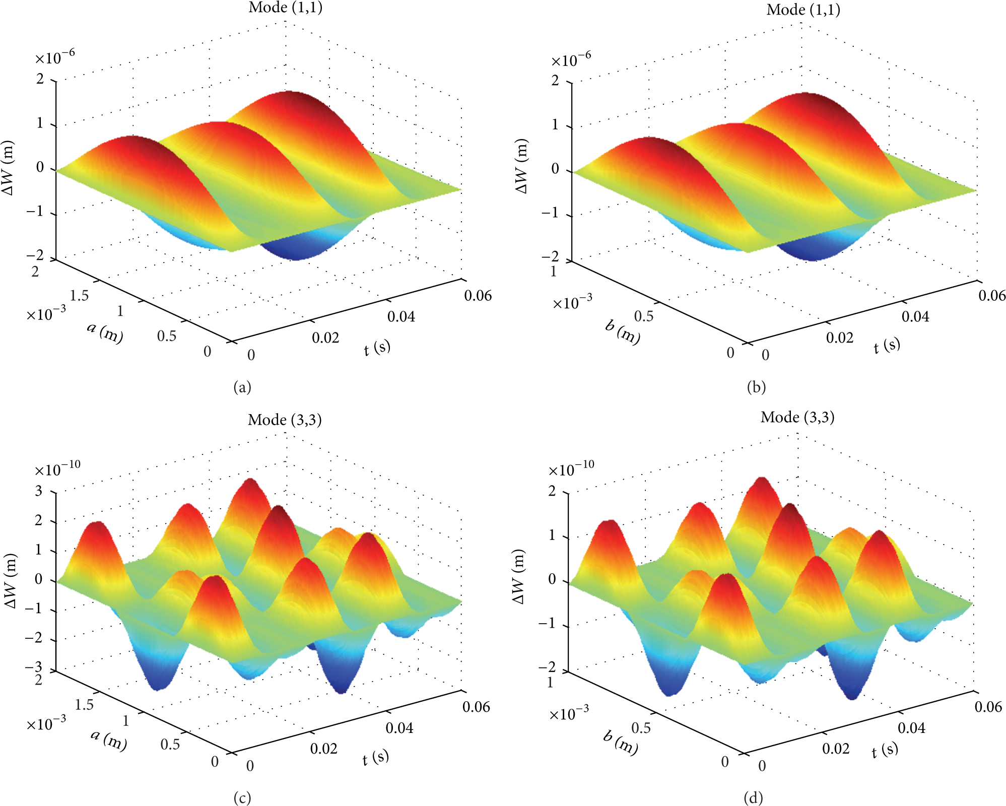
Coupled forced responses of the microplate.

The total coupled forced responses of the microplate.
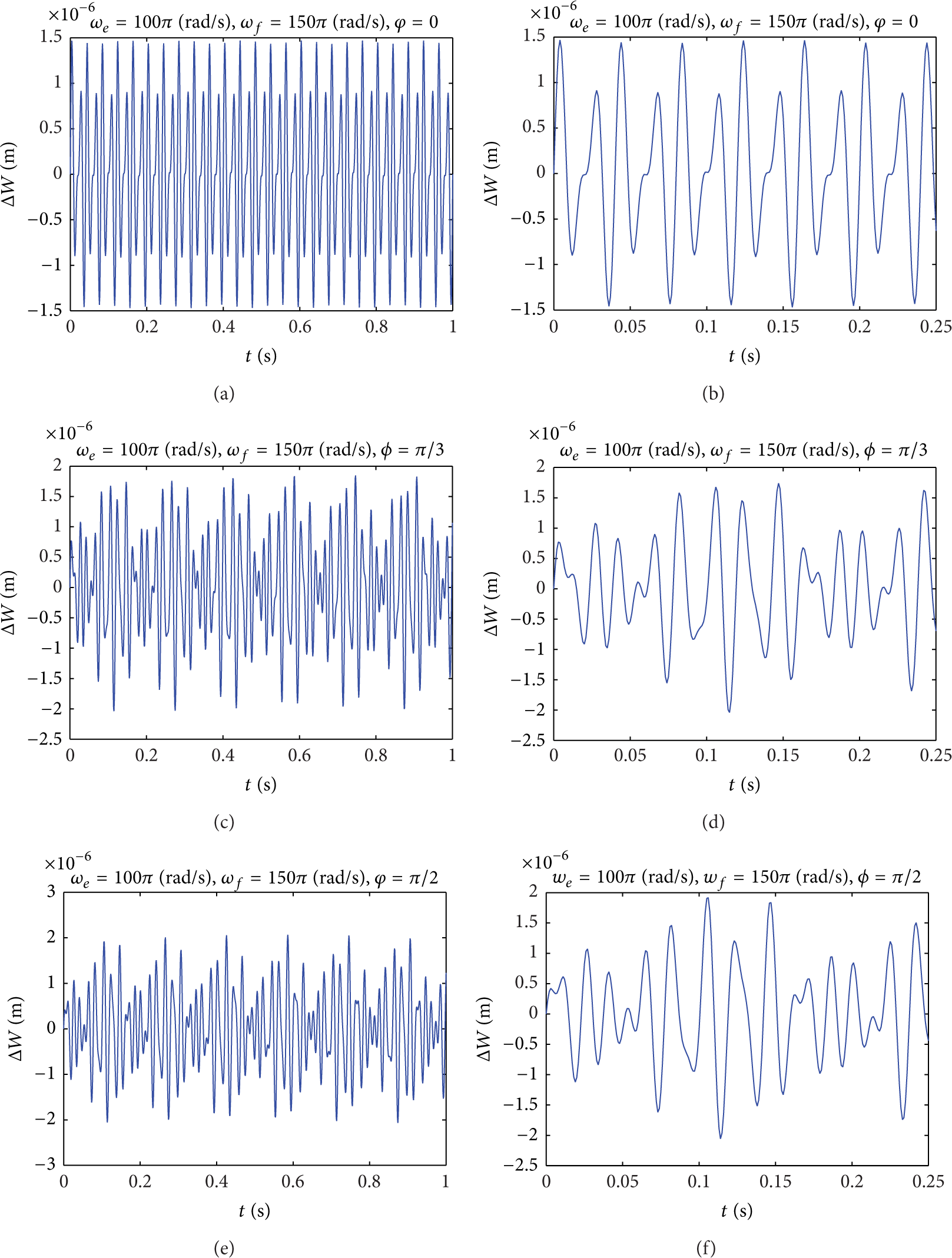
Changes of the coupled forced responses along with phase difference (ω f /ω e = 1.5).
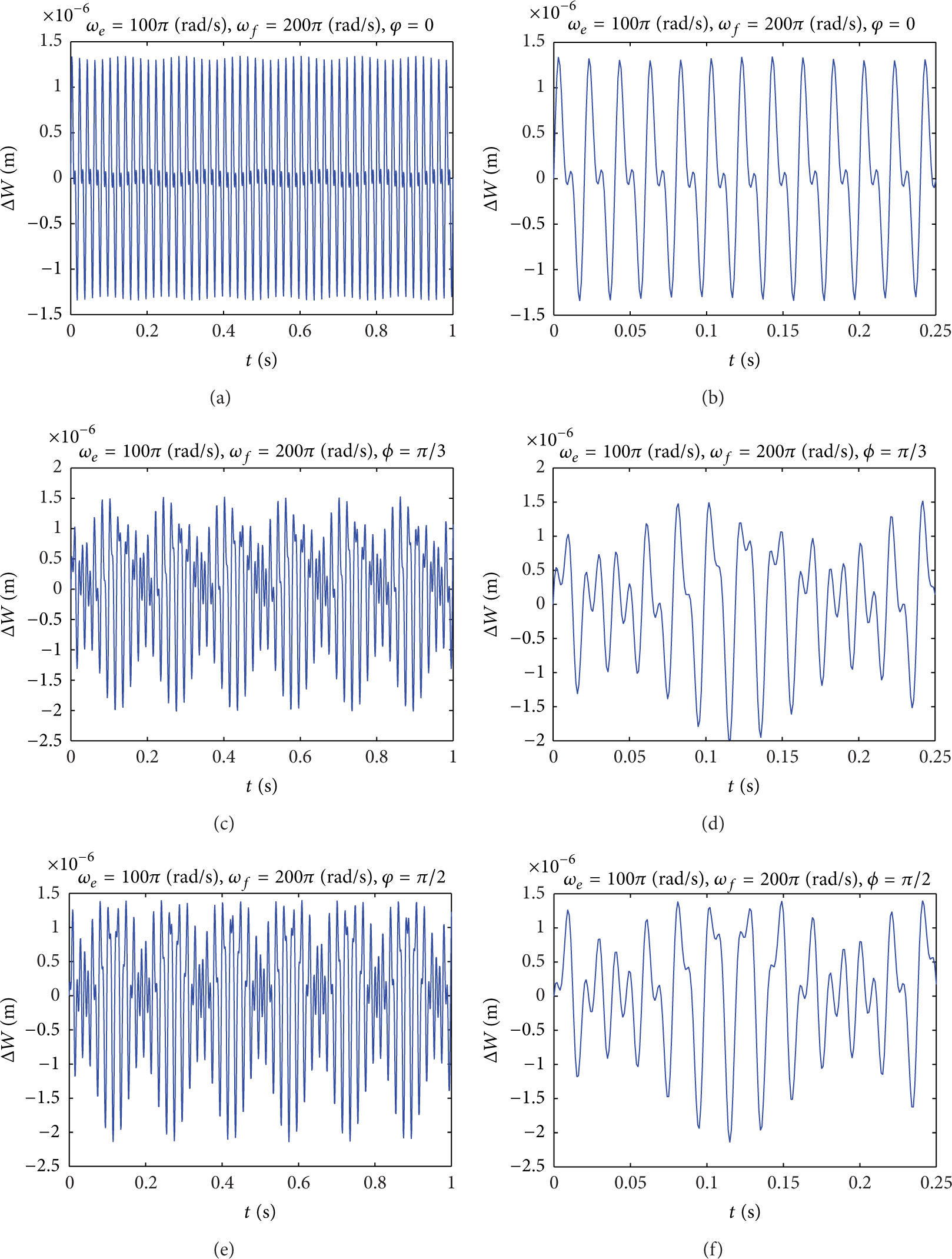
Changes of the coupled forced responses along with phase difference (ω f /ω e = 2).

Beat among coupled forced responses.
4. Conclusions
In this paper, the electromechanical coupled forced response of the microplate subjected to electrostatic force is investigated. The coupled forced responses of the microplate to voltage excitation and load excitation are analyzed. Beat vibration caused by the coupled forced response is also discussed. The results are useful for designing the dynamic performance of the microelectromechanical coupled system consisting of the microplate.
Conflict of Interests
The authors declare that there is no conflict of interests regarding the publication of this paper.
Footnotes
Acknowledgment
This project is supported by Key Basic Research Foundation in Hebei Province of China (13961701D).