
Abstract
The wavy vortex flow in the plain model was studied by experimental measurement; the preliminary feature of wavy vortex flow was obtained. This flow field in the plain model was also studied by numerical simulation. The reliability of numerical simulation was verified by comparing with the experimental and numerical simulation results. To study the slit wall effect on the wavy vortex flow regime, another two models with different slit number were considered; the slit number was 6 and 12. By comparing the wavy vortex flow field in different models, the axial fluctuation of Taylor vortices was found to be different, which was increased with the increasing of slit number. The maximum radial velocity from the inner cylinder to the outer one in the 6-slit number was increased by 12.7% compared to that of plain model. From the results of different circumferential position in the same slit model, it can be found that the maximum radial velocity in slit plane is significantly greater than that in other planes. The size of Taylor vortices in different models was also calculated, which was found to be increased in the 6-slit model but was not changed as the slit number increased further.
1. Introduction
The flow between two concentric cylinders, with the inner one rotating or both rotating, is called Taylor-Couette flow, which has been first studied by Taylor [1]. With increasing Reynolds number, the flow undergoes a series of transitions from circular Couette flow, to Taylor vortex flow, to wavy vortex flow, and to turbulent Taylor vortex flow [2]. Many researchers have studied the instability that causes Taylor vortices.
Yang and Lin [3] studied the Taylor-Couette flow transition process by flow visualization method; the aluminum particles were added to investigate the stability of flow field, they found as the rotation speed increased, the aluminum particles have the axial motion before the transition to Taylor vortex flow. In the study of Wei et al. [4], they changed the radius ratio of the model and kept the length constant; the number of Taylor vortices in the annual gap increases with the increasing of radius. Kádár and Balan [5] studied the aspect ratio effect on the transition process of Taylor-Couette flow; this study focused on the wavy vortex flow, and they found that after the transition to wavy vortex flow, as the Reynolds number is larger than the critical value, Taylor vortex flow can also be found, which means the transition process in unstable. Wereley and Lueptow [6] studied the spatiotemporal character of wavy vortex flow and found that the axial motion of the vortex centers decreases with increasing Reynolds number. Xiao et al. [7] studied the acceleration effect on the wavy vortex flow and found the wave speed and wavelength before them asymptote to a constant value, which is a function of the acceleration.
Most of the above studies were performed under plain wall conditions. That is, the annulus surface had a smooth plane. However, in engineering applications, the walls of cylinders generally have complex geometries, which are commonly seen in mechanical and electrical parts such as clutches, filters, and electric motors. An understanding of flow physics is helpful for improving the performance of such parts. Therefore, studies of a Taylor-Couette flow considering the effect of the cylinder wall shape were necessary. Lee et al. [8] studied Taylor-Couette system with different numbers of slits in the outer cylinder by using DPIV method and found that a larger number of axial slits accelerated the transition process flow wavy vortex flow to turbulent Taylor vortex flow but have no effect on the transition before wavy vortex flow. Liu et al. [9] studied the slit wall effect on flow stability in Taylor vortex flow regime and found that the vortex flow expanded into the slit wall; the intensity of the vorticity and the radial velocity increased in slit model. Hayase et al. [10] studied the heat transfer between rotating coaxial cylinders with periodically embedded cavities and found the flow in a cavity interacts with Taylor vortices in the annular space to enhance heat transfer.
As found in the previous study, the slit wall has obvious effect on the flow instability, but there is little study about the slit wall effect on the wavy vortex flow regime; only Lee et al. [8] measured the wavy vortex flow field in different slit models, but they only obtained the effect of slit number on critical Reynolds number from Taylor vortex flow to wavy vortex flow. Furthermore, the flow field measured by DPIV in their study was limited; because of the limitation of measuring field, the slit number effect on the vortex size cannot be obtained precisely. In our study, based on the investigation of slit wall effect on Taylor vortex flow [9], we studied the wavy vortex flow in detail by PIV measurement and CFD calculation. By comparing the results in three different models, the slit wall effect on the stability of wavy vortex flow was obtained. This study can help to understand flow instability phenomena affected by wall geometry.
2. Experimental Apparatus and Results
2.1. Experimental Apparatus
Figure 1 shows the experimental apparatus and setup used to measure the velocity field. The inner cylinder was made of aluminum pipe with black coating to prevent the reflection of a laser, which has an external radius r i = 33 mm. The outer cylinder was made of acryl and had an inner radius r o = 40 mm. The annulus gap (d) between the cylinders was 7 mm and the length of the cylinders (L) was 336 mm. The radius ratio (r i /r o ) and aspect ratio (L/d) were 0.825 and 48, respectively, following the studies of Cole [11] and Wereley and Lueptow [6]. The geometry of the experimental model was shown in Figure 2. This micro stepper motor was controlled through a computer, which allowed for the precise control of angular velocity (Ω) and the acceleration to the preset velocity. The outer cylinder was kept stationary. The working fluid sodium iodide solution filled the annular gaps and the space between the outer cylinder and the enclosure box in order to avoid the light refraction effect. The details of this method were explained in a previous study by Lee et al. [8].

Schematic diagrams of the experimental apparatus.

Geometries of plain model.
Since the viscosity of the sodium iodide solution alters with temperature, it needs to be guaranteed that temperature of the annulus fluid keeps constant in order to ensure measurement accuracy. Therefore, we were careful to ensure constant temperature conditions in the model and installed a water jacket in the space between the enclosure box and the outer cylinder to control the temperature of the solution, while also continuously monitoring the temperature of the working fluid.
The instantaneous velocity fields were measured using the PIV system from TSI Company. The double pulse Nd: Yag laser was used as a light source. The CCD camera perpendicular to the laser was used to record the images of tracer particle. The conventional cross-correlation PIV method was used to do the image processing; the interrogation window size was 32 × 32 pixels with 50% overlap. Besides, Tecplot combined with MATLAB was used in the postprocessing of experimental results.
In this experiment, the rotational speed was expressed as a rotating Reynolds number, which is defined as Re = r i dΩ/ν, where Ω is the angular velocity of the inner cylinder. From the experimental results of Lee et al. [8], as the Reynolds number is within the range of 124 to 1145, wavy vortex flow will appear in plain model. In this paper, the rotation angular velocity of inner cylinder is fixed to 1.316 rad/s, and the Reynolds number is 200.
2.2. Experimental Results
Figure 3 shows instantaneous flow fields on the radial-axial plane while Reynolds number is 200. The time interval between each result is 1.2 s, and the figures are labeled T1, T2, T3, and T4. The axial position, Z* = z/d, and the radial position, R* = (r o − r i )/d, were normalized by the annulus gap width. Compared with the Taylor vortex flow [8], the axial position of Taylor vortices in wavy vortex flow regime changes periodically and the flow becomes unsteady.

Instantaneous velocity fields of wavy vortex flow.
Figure 4 shows the radial velocity components along the axial direction at the R* = 0.5 location. The radial velocity V r larger than zero represents the motion from the inner cylinder to the outer. It can be seen from this figure that the velocity profile corresponding to the outflow is narrower and stronger than that corresponding to the inflow, which can be seen all the time. The maximum outflow velocity is about 35.2% higher than that of the inflow velocity. This occurs because the distance between the two vortex centers of a vortex pair is shorter than that of two adjacent vortex pairs, and the outflow between the vortex centers of a vortex pair is stronger than the inflow between two adjacent vortex pairs. This phenomenon can be found during the evolution process of wavy vortex flow. And from Figure 4, the amplitude of wavy vortex flow can be calculated, which is about 0.42d.

Radial velocity profile at different times.
Because of the limitation of PIV experimental measurement, the axial size and number of Taylor vortices in the annulus cannot be calculated accurately, and it is also difficult to obtain the velocity in different circumferential planes at the same time. Thus this paper takes the numerical simulation to research the characteristic of wavy vortex in different models.
3. Numerical Method
3.1. Calculation Model
Figure 5 shows the calculation models in this paper. The radius of the inner and outer cylinders, annulus width, and length of them are consistent with the plain models in the experiment. Figures 5(b) and 5(c) are slit models with the number of slits being 6 and 12, respectively; the width and depth of each slit are 5 mm.
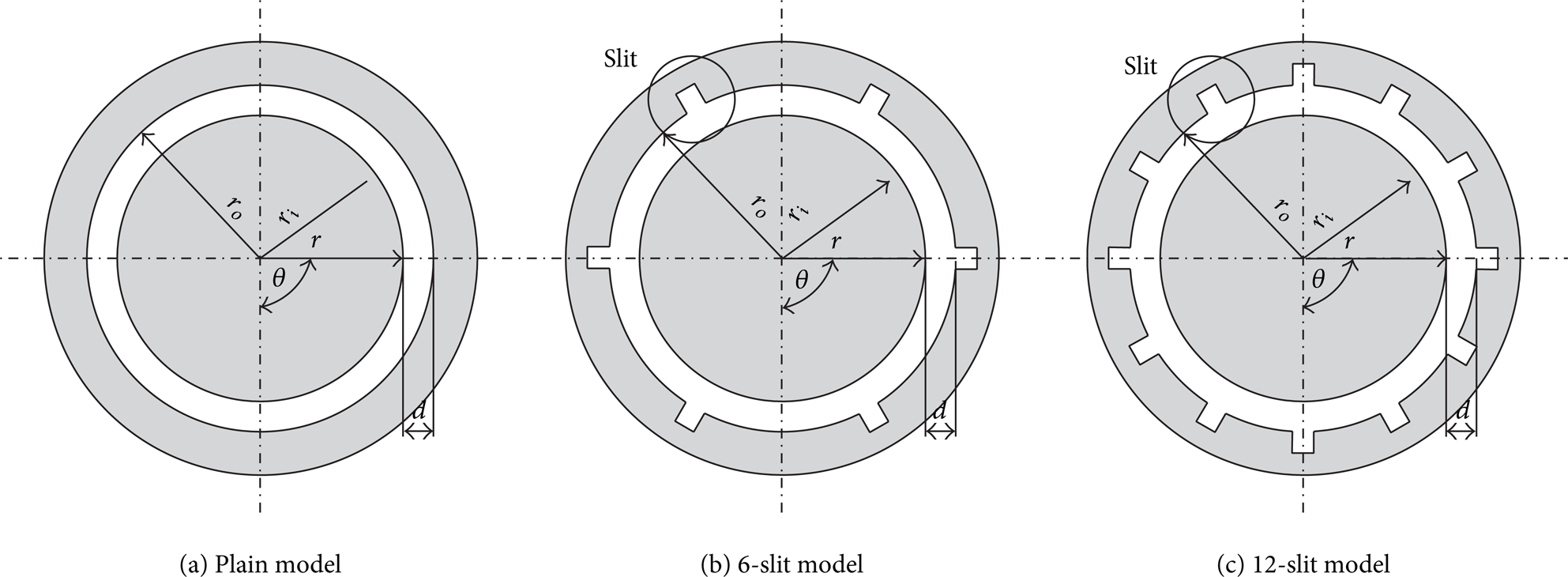
Geometries of calculation models.
3.2. Numerical Mode
Structured mesh is applied in this paper, and the mesh of 12-slit model is shown in Figure 6. In order to obtain an accurate calculation result, the mesh near the wall is increased. Commercial software FLUENT 13 is used to solve the laminar flow. In this version, the solver is pressure-based and transient. The viscous model is laminar. The material of fluid is sodium iodide solution, with kinematic viscosity 1.52 cSt and density 1780 kg/m3. Underrelaxation factors are 0.3 for pressure and 0.7 for momentum. The way of discretization is second order for pressure, SIMPLEC for pressure-velocity coupling, and second-order upwind for momentum. Solution is computed from inner cylinder, and all initial values are zero unless specified. All the convergence criterions are 0.0001. The outer cylinder is resting, and the inner cylinder is rotating with the speed of 1.316 rad/s, and the periodic boundary condition is adopted to the ends of the model. The characteristic of the vortex flow is described by the convergent calculation results.
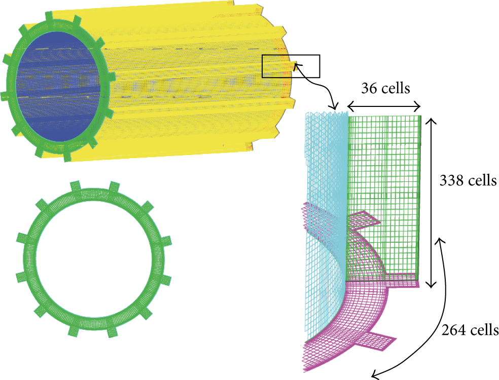
Mesh of 12-slit model.
4. Analysis of Simulation Results
4.1. Numerical Validity
Figure 7 shows the velocity field in radial-axial plane of plain model, which is obtained by numerical calculation when Reynolds number is 200. The time interval between each result is 1.2 s, and therefore the figures are labeled T1, T2, T3, and T4.
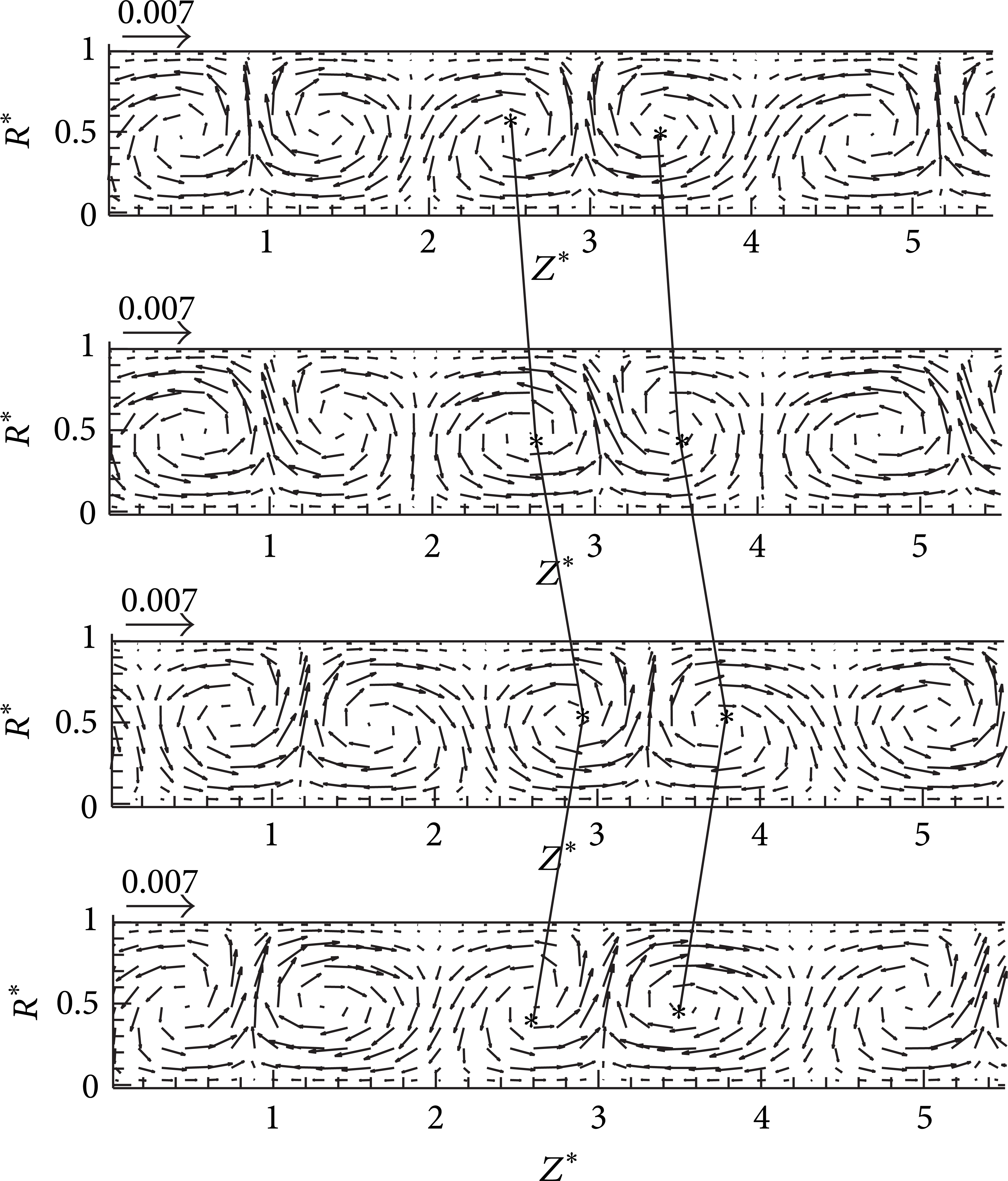
Instantaneous velocity fields of numerical simulation.
Comparing the velocity field of Figure 7 with Figure 3, it can be seen that the flow fields of wavy vortex flow obtained from calculation and experiment are consistent. From Figure 7, it can be found that the adjacent vortex rotates in the opposite direction, and vortex center is in the middle of the annulus gap. By observing the movement of vortex center, axial amplitude of the wavy vortex flow can be calculated, which is 0.42d. This result also agrees well with the experimental result. In order to verify the accuracy of numerical calculation further, the radial velocity distribution at location R* = 0.5 is extracted from numerical simulation and experimental results, which is shown in Figure 8. From this figure, it is evident that radial velocity distributions obtained by numerical calculation and experiment have little difference; the maximum error of the radial velocity amplitude is about 4.4%. Thus it proves that numerical simulation method used in this paper is reliable.

Radial velocity profile of PIV and CFD.
4.2. Characteristic of Wavy Vortex Flow in Plain Model
According to ω = dv r /dz − dv z /dr, vorticity can be calculated from the velocity result, and V z represents axial velocity. The vorticity and radial velocity in line R* = 0.5 at time T1 are extracted, which is shown in Figure 9. It can be found that the vorticity has zero correspondence to the crest and trough position of radial velocity profile curve, and the radial velocity has zero correspondence to the crest and trough position of the vorticity profile curve. This means that the maximum vorticity appears in the center position of the vortex, whereas the minimum radial velocity and the maximum radial velocity appear in the center part of a Taylor vortex pair or between two Taylor vortex pairs, where the vorticity has the minimum value.
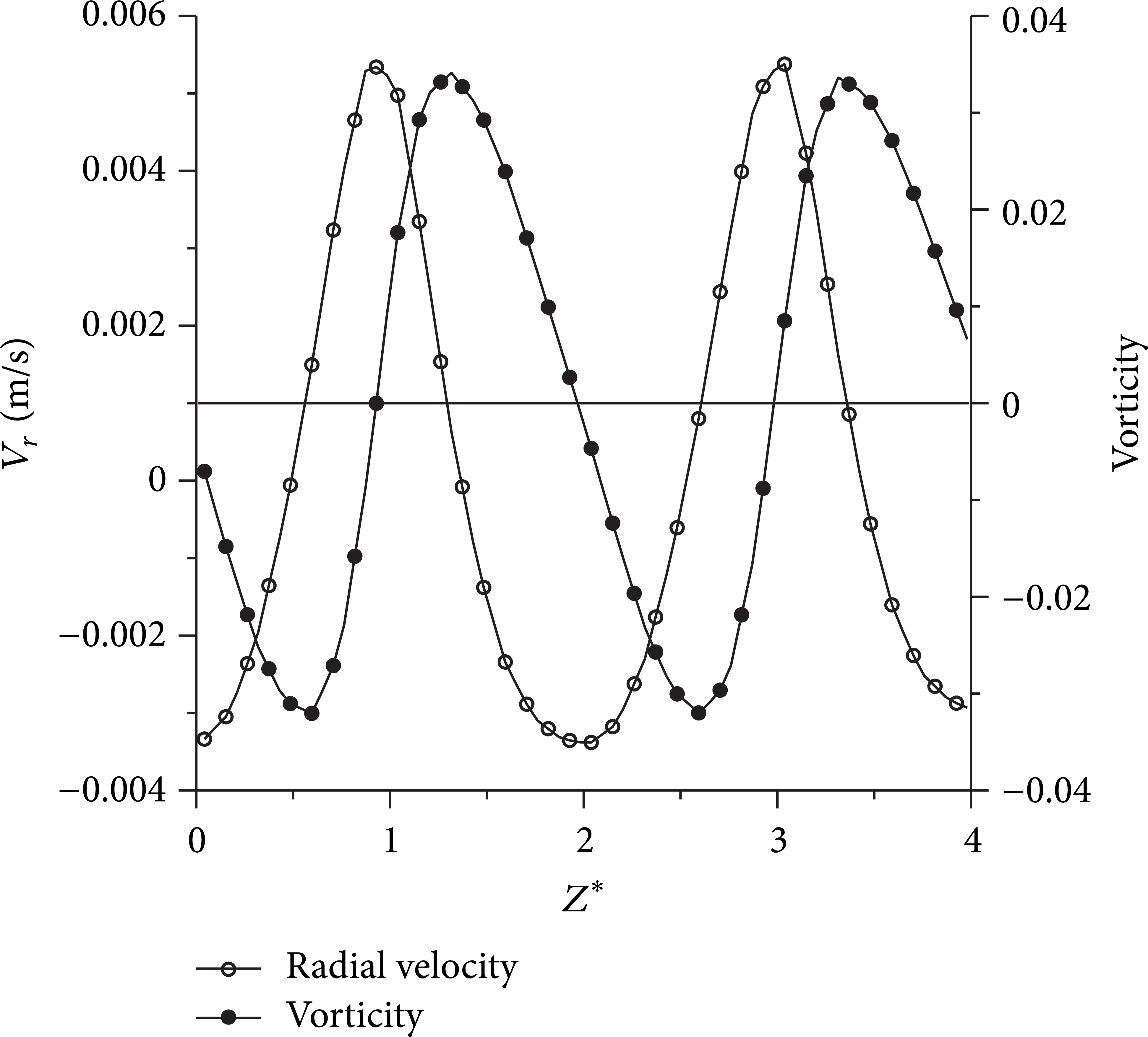
Vorticity and radial velocity profile at T1.
Figure 10 shows the radial and axial velocity profile of the axial position Z* = 3 at T1. As can be seen from this figure, the axial velocity profile in the radial direction approximates a sine curve, which means the axial velocity increases from the inner cylinder to R* = 0.2 and then decreases to zero in the middle position of the annulus gap. The axial velocity has a maximum value at R* = 0.2, which is about twice larger than that of R* = 0.8. The radial velocity profile is similar to a parabola, and the maximum value appears when R* is 0.5, the middle position of the annulus gap, where the axial velocity is nearly zero.
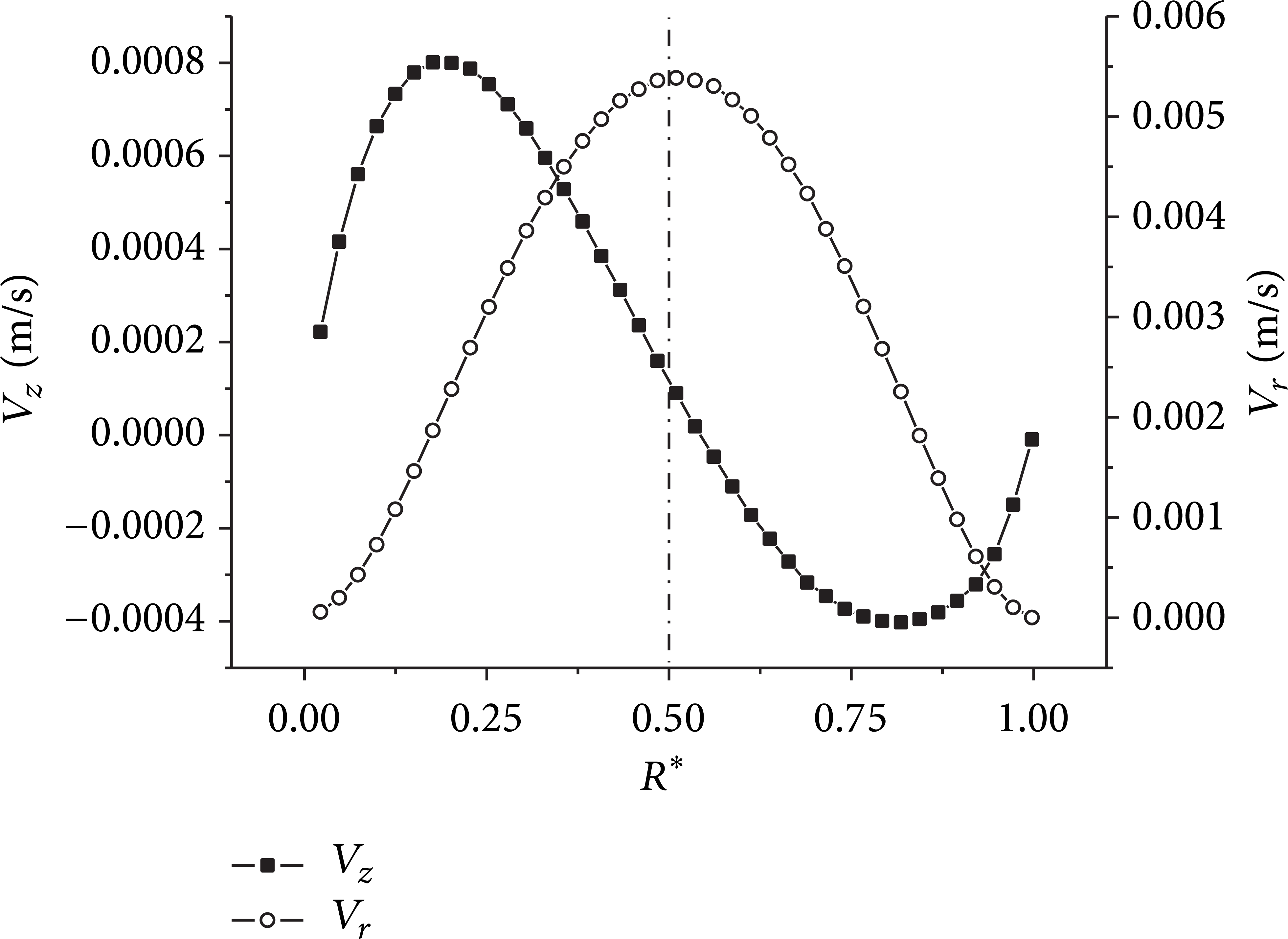
Radial and axial velocity profile in Z* = 3 at T1.
4.3. Velocity Distribution in Slit Models
Figure 11 shows the velocity distribution at different times of 6-slit and 12-slit models while Reynolds number is 200. This flow field has the feature of wavy vortex flow, which means the wavy vortex flow can be found in both slit models at this Reynolds number. The flow in the annulus gap expanded into the slit space, and the vortex size became larger compared with that of plain model. The amplitude of axial fluctuation of Taylor vortices is 0.51d and 0.59d, respectively; this result verifies that the amplitude of wavy vortex flow increases appropriately as the slit number rises [8].
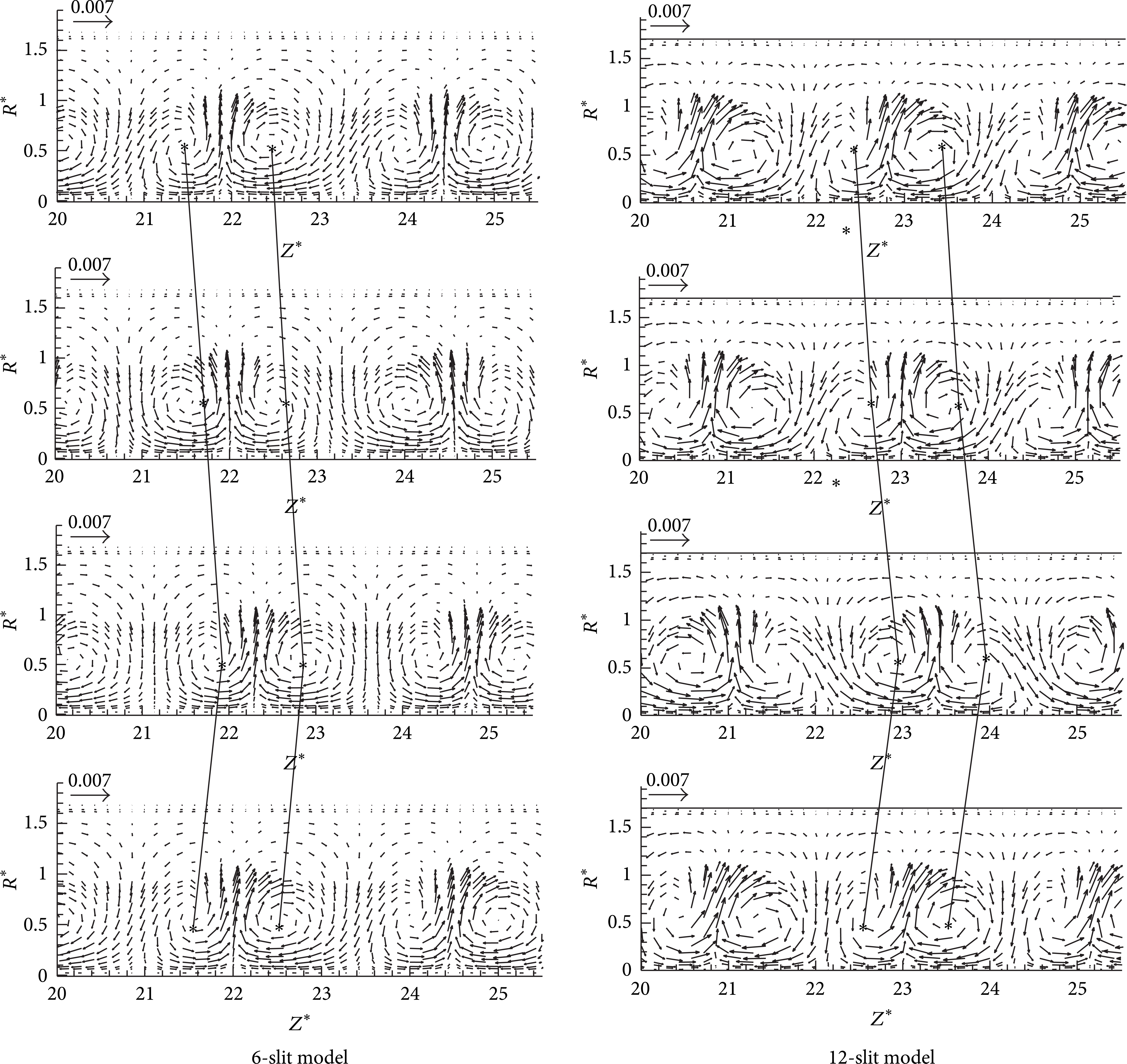
Instantaneous velocity fields in slit models at Re = 200.
Figure 12 shows the radial velocity profile at different times in 6-slit model at R* = 0.5, the middle position of the annulus gap. It is evident that motion regularity of wavy vortex flow in slit model and plain wall model is similar, but size of the Taylor vortices somewhat increases due to the influence of slit wall. In comparison with Figure 8, it can be seen that the radial velocity increases in the 6-slit model. The distance between adjacent troughs in the radial velocity profile is axial size of Taylor vortices. From the calculation results, the axial size of Taylor vortices in 6-slit model increased by 10.1% compared to that of plain wall model, which illustrates that slit wall not only increases the radial velocity of the vortex, but also augments the axial size of Taylor vortices.

Radial velocity profile at different times in 6-slit model.
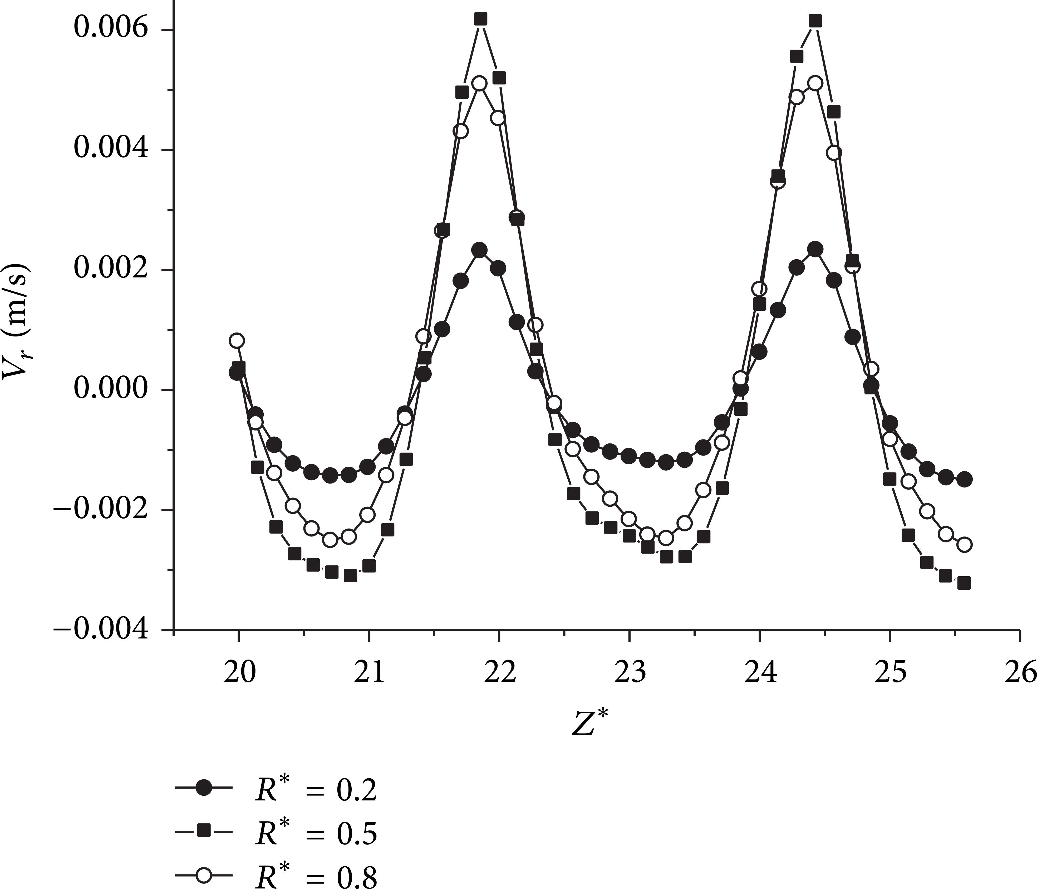
In order to further understand the influence of slit wall on wavy vortex flow, the radial velocity profile in plain, 6-slit, and 12-slit models is compared, which is shown in Figure 13. The velocity data in this figure is extracted from the middle position of the gap at T1, circumferential angle θ being 0° in each model. The maximum of radial velocity from the inner cylinder to the outer in 12-slit model is 20% larger compared to that of plain model, but the difference of radial velocities from outer cylinder to inner one is very small among the three models. It illustrates that the slit wall facilitates the radial outward flow but has little influence on the radial movement into the inner cylinder. Figure 14 shows the radial velocity profile when R* is 0.2, 0.5, and 0.8. It is evident from the curve that amplitude of the radial velocity in the gap central is the largest. Meanwhile, the radial velocity in R* = 0.8 is obviously larger than that in R* = 0.2, which verifies that slit wall enhances the radial flow.

Radial velocity profile in different models.
Radial velocity profile in 6-silt model.
Figure 15 shows the radial velocity profile of each circumferential plane in 12-slit model when R* is 0.5. The minimum velocity in each circumferential plane is similar, but the maximum one has big difference. The maximum radial velocity in slit space is significantly greater than that in annulus gap, which is about 15.2% larger. The main reason is that fluid in the annulus spreads into slit space gradually. The slit wall intensified the radial flow in the annulus, which increased the radial velocity in the slit space.
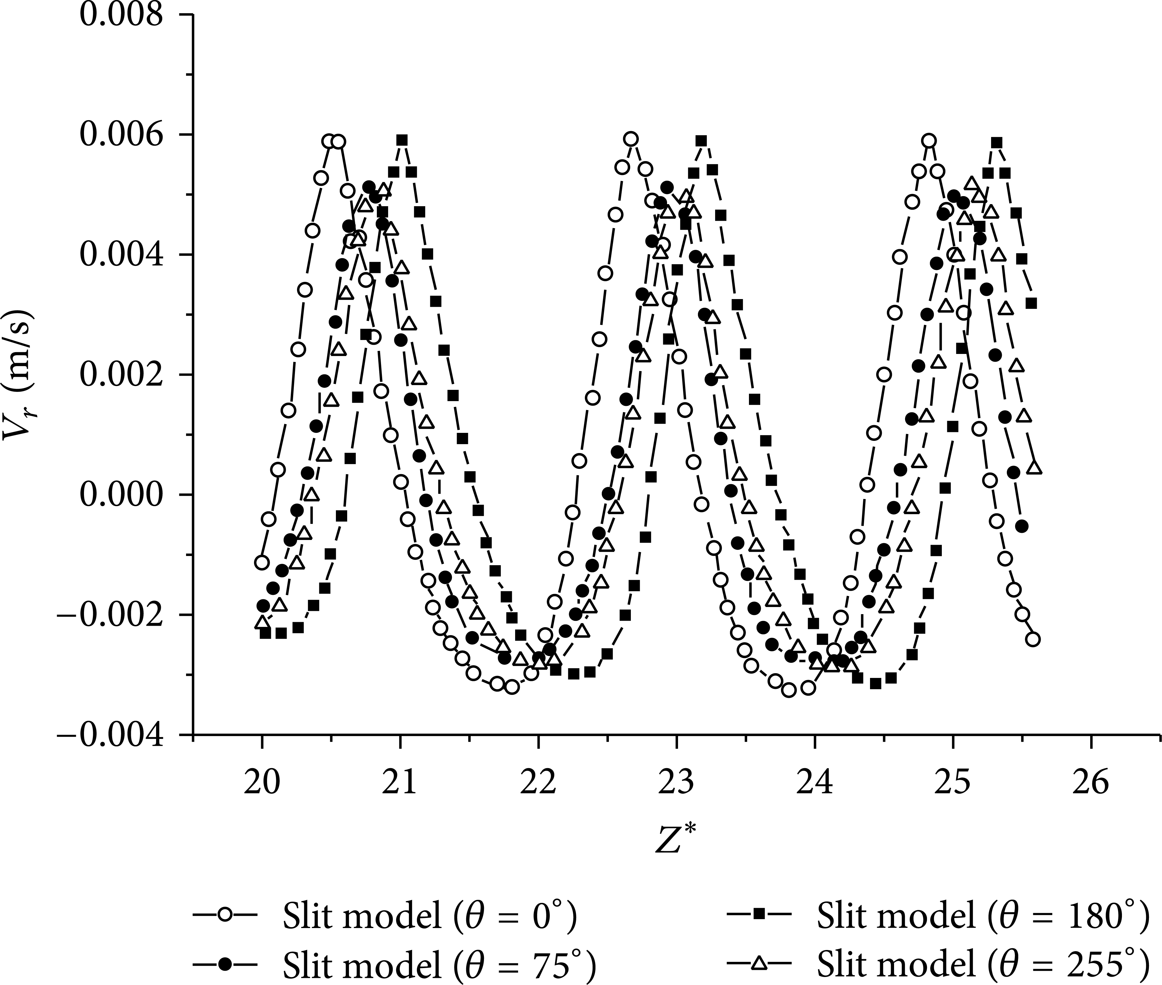
Radial velocity profile in different circumferential planes.
Figure 16 shows the radial-azimuthal velocity field at the slit space when Z* is 24.5 in 6-slit model. As can be found in Figure 16(a), tangential velocity dominates in the fluid flow in radial-azimuthal plane, and velocity decreases gradually in the direction from inner cylinder to outer cylinder. Figures 16(b) and 16(c) show the velocity field in slit spaces 1 and 2 at the time of T1. Compared with these two Figures, it can be found the flow field in different slit space differs a lot, which means that the flow in the slit space also has the characteristic of wavy flow. Figures 16(d), 16(e), and 16(f) show the velocity field in slit space 1 at different times; the fluid flows from slit wall region to the annulus gap at T1 and T2 but remains as vortex flow at T3 and T4. Meanwhile, continuous changing of secondary flow in slit space means there is periodical interaction between the slit space and annulus gap.
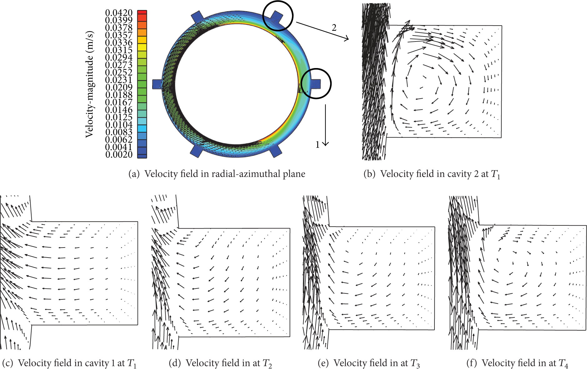
Velocity field in radial-azimuthal plane.
From the numerical calculation, the flow field in the whole model can be obtained, which overcomes the shortcomings of PIV experimental. And Taylor vortices’ number can be calculated, which is 22 pairs in plain model and 18 pairs in the 6-slit and 12-slit models. Table 1 shows the maximum value of the radial velocity and axial velocity in different models and the amplitude of axial fluctuation and axial size of Taylor vortices.
Comparison of different models.

From the data in Table 1, it can be found that the axial size of Taylor vortices in 6-slit model and 12-slit model is the same, which increased about 10% compared to that in plain model. When the slit number is 6, the maximum axial velocity increases about 4.7% compared to that in plain model. Compared with the increase of 12.7% on the radial velocity, the influence of small slit wall on the axial velocity is relatively weaker. When the slit number increases to 12, the maximum value of V r and V z has increased by 14.3% and 8.7% compared to plain model, which means that the axial and radial velocity of Taylor vortices are intensified as the slit number increases. The axial amplitude of wavy vortex in 6-slit model increases about 21.4% compared with that of plain model and increases about 40.4% in 12-slit model, which means that the axial fluctuation of wavy vortex flow changes significantly as the slit number increases.
5. Conclusion
In this paper, wavy vortex flow in plain and slit wall models was calculated by CFD. The result of experimental and CFD was compared, which proved that the CFD method used in this paper is reliable. The following conclusion was obtained by comparing the results of different models.
The flow field distribution at different time in slit models was analyzed when the Reynolds number is 200. The wavy vortex can be found in all the models considered in this study. In the slit model, by comparing the radial velocity in different radial position, it can be found the radial velocity near the slit space is larger than that near the inner cylinder, which has a maximum value in the middle of the annulus gap. And also it can be found the flow field in different slit space differs a lot because of the periodical interaction between the slit space and annulus gap. By further comparison of the results in different models, it can be found the slit wall increases the vortex size and axial fluctuation of the flow obviously, as the slit number increases from 6 to 12; there is no significant change of the vortex size, but the axial fluctuation still increases obviously.
Conflict of Interests
The authors declare that there is no conflict of interests regarding the publication of this paper.
Footnotes
Acknowledgments
This work was supported by the National Natural Science Foundations of China (51206062 and 11102073), China Postdoctoral Science Foundation (2013M540420), Specialized Research Fund for the Doctoral Program of Higher Education (20113227120012), and A Project Funded by the Priority Academic Program Development of Jiangsu Higher Education Institutions. One of the authors (Hyoung-Bum Kim) was supported by the Priority Research Centers Program (2012-048078) of the Korean Government.