
Abstract
This paper presents the mechanical and control system design of the latest humanoid robot platform, BHR-5, from Beijing Institute of Technology. The robot was developed as a comprehensive platform to investigate the planning and control for the fast responsive motion under unforeseen circumstances, for example, playing table-tennis. It has improvement on mechanical structure, stiffness, and reliability. An open control architecture based on concurrent multichannel communication mode of CAN bus is proposed to upgrade the real-time communication performance and the expansibility of the control system. Experiments on walking and playing table-tennis validate the effectiveness of the design.
1. Introduction
A humanoid robot features the body shape analogous to that of human being. This makes it possess the locomotion and manipulation capabilities similar to human being. It is expected that a humanoid robot may work or assist people in the human-centered environment without a need to adapt itself or to modify the environment. Therefore many researchers have made great efforts in this field. In recent decades, a series of humanoid robots such as ASIMO [1, 2], WABIAN [3], HRP [4, 5], QRIO [6] KHR [7], HRP3L-JSK [8], JOHNNIE [9], Atlas [10], THBIP [11], BHR [12, 13], and a robot from Toyota Corp. [14] have been unveiled. Some researchers investigated the advanced control methods for biped robots [15–17].
Beijing Institute of Technology (BIT) launched the research on humanoid robots in 2000 and has developed generations of humanoid robot named BHR (BIT Humanoid Robots). The first four generations, from BHR-1 to BHR-4, successfully perform walking and complicated coordinated motions, such as Taichi, swordplay, and facial expressions, without external cables [12, 18]. Due to the limit of the mechanical structure and mechatronics system, the previous generations of robots could not satisfy the requirements of the fast responsively coordinated whole-body motion under unforeseen circumstances; for example, they cannot play table-tennis. Hence, a new humanoid robot, BHR-5, is developed.
To achieve fast tasks, a humanoid robot should possess the property of high stiffness, light weight and inertia, high power output, and more rigorous real-time information sensing and processing capability. For BHR-5 platform, an integration design for mechanical structure and the casting manufacturing method was explored to enhance the stiffness. A two-degree of freedom (DOF) waist was added to improve agility and enlarge the workspace. The arm of the robot was changed from 6 DOFs to a redundant configuration to reinforce the agility of the manipulation. A flexible foot for landing impact absorption and foot attitude estimation was explored. An open control architecture based on concurrent multichannel communication mode of CAN (control area network) bus was proposed to shorten the periodical time of real-time communication to 2 msec. This design greatly enhanced capability of information sensing and processing and stability of the robot.
The remainder of this paper is organized as follows. The overview of the humanoid robot is described in Section 2. In Section 3, a mechanical design method is presented to enhance the robot's stiffness and reliability. In Section 4, the open control architecture is presented, which enables short communication period and good expansibility. In Section 5, the motion planning and experiments on walking and playingtable-tennis are described. Finally, the conclusions are given in Section 6.
2. Overview of the Humanoid Robot
Our latest humanoid robot platform, BHR-5, shown in Figure 1, consists of two legs, two redundant arms, a torso, and a head. It has a total of 30 DOFs. The height of the robot is 1.62 m, and its weight is 65 kg. It is capable of walking up to 2.0 km/h and manipulating a variety of objects, for example, playing Table-tennis. There are 2 color cameras, 3 gyroscopes and 3 accelerometers, and 2 six-axis force/torque sensors in the robot. There is a distributed real-time control system for the motion control and information acquisition. The mechanical frame and skeleton are made of aluminum, and the exterior is made of hard plastic. Every joint is actuated by brushless DC motor and harmonic drive gear. The robot is powered by lithium-polymer battery. The detailed specifications of legs and arms are shown in Tables 1 and 2.
Specifications of the leg.

Specifications of the arm.


The humanoid robot.
3. Mechanical Design of the BHR-5 Robot
3.1. Design Principles
The mechanical design of BHR-5 follows the main principles below.
Bionic principles: the robot should have higher similarity in structures and functions with human being and human-like height, size, DOFs, and the movement ranges.
High stiffness and light weight principles: high stiffness leads to less mechanical deformation and flexible vibration. Low weight may reduce the requirements of actuator's power and torque output. This would be useful to the balance control.
Integration design principles: to enhance the stiffness and reliability, an integration design for the mechanical structure and the casting manufacturing were employed.
Versatility principles: this robot is expected as a comprehensive research platform for robotics techniques, so it should be competent for the researcher to investigate diverse robotics issues.
Reliability and maintainability principles: there are more than 30 joints in the robot. Each joint is composed of motor, reducer, sensors, and motor controller. The mechatronics system of the robot is quite complicated. The reliability is vital to the robot. For example, even if only one joint has faulted, the robot would risk tipping over.
3.2. Mechanical Structure Design
Based on the design principles, we designed the waist, leg, arm, torso, foot, and their connections. Every active joint is driven by brushless DC motor from Maxon Company, and harmonic driver is employed as reducer in each joint. The power of all the motors in the legs is all 200 W. The harmonic gear has the features of no-backlash and high reduction ratios in small space with low weight. The total gear ratio of each joint in the legs is 320.
To reduce weight and preserve stiffness and strength, we used the integration design for the leg instead of our previous discrete design. We dug holes to decrease the weight and also employed the finite element analysis (FEA) to check the strength and stiffness of the mechanical components. Timing belt is adopted to change the gear ratio and the motion transmission link in terms of transmission mode and arrangement of the motor and moving joint. Figure 2 shows the discrete design of the thigh, hip pitch joint, and the ankle joint of the BHR-3 and the integration design for the BHR-5. Figure 3 shows the comparison of the ankle design between the BHR-3 and BHR-5. In our previous robots, the ankle joint consisting of the pitch and roll DOF are assembled by many discrete components with bolts and screws. In the newly designed one, there is only an entire cross part with a hole for the electric cables to pass through. This enhances greatly the stiffness, strength, and reliability. Analogously, the same cross part is used for the joints in hip.
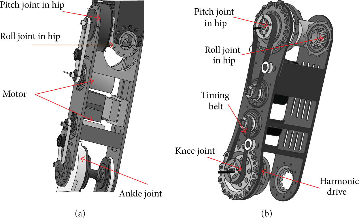
Comparison of the thigh design between BHR-3 (a) and BHR-5 (b).

Comparison of the ankle joint design between BHR-3 and BHR-5 (b).
The front view (left figure) and lateral view (right figure) of the whole right leg are shown in Figure 4.

Right leg of the BHR-5 robot.
More DOFs are required to achieve the complicated motions, like playing table-tennis. A waist can help the robot to enlarge the workspace of the arm's end-effector through yaw and roll motion. Moreover, the motion of the waist joint can be used to compensate the torque that resulted from the legs during swing. The two-DOF waist is shown in Figure 5.

Two-DOF waist joint of BHR-5 robot.
The design of the feet is crucial for humanoid robots because the feet are the main contact part between the robot and the environment. This design is to build up a new flexible robot foot capable of performing an effective role in landing impact absorption and foot attitude estimation. As a part of a humanoid robot, some basic characteristics should be met such as small size, light weigh, and capable of dealing with rough terrain, stairs, and obstacle environments [19]. The foot structure is illustrated in Figure 6. The upper panel is attached with the six-axis force/torque sensor, which is directly linked together with the leg. At the back of the aluminum base board, there is a sunken structure which provides a rail-like mechanism for the upper panel to move vertically with an appropriate clearance. Four pieces of rubber cushion are placed between the upper panel and the aluminum base board, acting as impact absorption. Four pieces of rubber cushion are sticked onto the four corners of the underside of the aluminum base board, which is expected to keep the humanoid robot away from slipping and reduce the shock of impact between the base board and floor.

Flexible foot of BHR-5 robot.
The arm of BHR-5 robot has seven DOFs configured in an anthropomorphic way: 3 DOFs in the shoulder, 1 DOF in the elbow, and 3 DOFs in the wrist. The axes of the three joints in the shoulder intersect at one point. The axes of the three joints in the wrist intersect at another point. The spherical wrist enables the arm to change the posture of the end-effector suddenly without utilizing the whole arm to imitate an abrupt wrist motion usually employed by human. The arm is fixed on a frame (torso). To enlarge the valid workspace leftward for right arm, vice versa, rightward for the left arm and to decrease the possibility of collision between end-effector and the torso, there is an angle of 10 degrees indenting along the coronal plane. The front and left view of the right arm are shown in Figure 7. The left arm is almost the same to the right arm.

Front and left view of the right arm.
The mass distribution of the designed robot is shown in the Table 3.
Mass distribution.

4. Control System of the BHR-5 Robot
Generally, a humanoid robot has more than thirty DOFs to be servoactuated and should deal with multiple sensor information, which requires high speed computing capability. Moreover, the control system must be small sized and of low weight so as to become well embedded in the humanoid body. Therefore, the performance and architecture of the control system designed for the humanoid robot are crucial problems.
Up to date, some humanoid robot, for example, WABIAN-2 [3], adopted the centralized control architecture, and some other humanoid robots such as Hubo [20] and BHR-3 [13] employed the distributed control architecture. But for the latter one, the periodical time of distributed communication is comparatively long relative to the centralized architecture. For example, the periodical control time of the Hubo is 10 ms, and BHR-3's is 5 ms. Usually, shorter periodical time is expected for a humanoid robot to acquire its current state and then to regulate itself to keep balance. In addition, as a robotics platform, a humanoid robot should have expansibility to interface with sensors, motor drivers, and controllers. To solve these problems, we propose an open control architecture based on concurrent multichannel communication mode of CAN bus to shorten greatly the periodical time to 2 ms.
4.1. Control Hardware Architecture
The control system of the humanoid robot is composed of two main parts: the vision and audio computer system and the real-time motion control system (Figure 8). The vision and audio computer system is responsible for vision and audio processing, and its operating system is Windows. The motion control system is used to coordinate the acquisition of sensors and the real-time servocontrol for all the joint controllers of the legs, arms, torso, and head. To achieve real-time capability, the operating system of the motion control computer is Linux plus RT-Linux core. The CAN bus works at 1 Mbps. The Ethernet and CAN bus are used to exchange non-real-time data and real-time data, respectively, between the vision and audio computer and the motion control computer.

Control system architecture for BHR-5 robot.
Two 6-axis force/torque sensors are located on each foot to measure the contact force and torque between the foot and the ground. And then force/torque data is acquired by a 4-channel PCI interface card to compute the actual COP (center of pressure) for stability control.
In order to enhance the expansibility of the control system, CANopen protocols are employed. Moreover, in order to reinforce the communication speed, we use three commercial CAN interface cards to make six CAN channels communicate concurrently. The algorithm for concurrently communication is shown in Algorithms 1 and 2. These algorithms result in the total time consumption of CAN bus communication in every control period that is around 0.5 ms. It should be pointed out that the CAN bus would work at the nonblock mode. To preserve enough time for carrying out motion planning and stability regulation algorithm, the periodical time of servocontrol is set at 2 ms.

Algorithm of concurrent receiving.

Algorithm of concurrent sending.
4.2. Motor Controller
The motor controller receives the reference trajectory and drives the motor to follow the reference trajectory. In BHR-5, the motor controller feeds back the encoder counter and serves as a finder of the joint home (zero) position. We developed a high power density and output motor driver for the BHR-5 robot [21]. It includes two PCB boards layered and linked with connectors. One is the control board and the other is the power board. Its size is 88 × 64 × 25 mm. Each controller regulates one motor. It has three types of control patterns: current control loop, velocity control loop, and position control loop. The rated voltage is 100 V, and the peak current is 50 A. It complies with the major entries of the CANopen DS301 and DS402 protocol. For example, we employ the object 0×2002 for position reference value and 0×6064 for position feedback value. The object 0×2002 is mapped to RPDO1 and the object 0×6064 is mapped to TPDO1 via SDOs. The interpolated position mode is used in BHR-5 to coordinate the motion of all the motors.
We determine the home (zero) position of each joint by the combination of Hall sensors with Z-pulse (index pulse) of incremental encoder. A Hall circuit board with three or six Hall switch sensors is mounted on one part of the joint, and an alnico is mounted on the opposite, as shown in Figure 9. The Hall sensors and alnico are used to detect relative displacement of joint approximately. The Z-pulse is used to determine the accurate position at each turn. In other words, the Hall sensor is used to indicate which rotary turn generates the Z-pulse. Hence, the accurate home point can be determined by this method. The board is connected to the driver. Except for zero point determination, it can also limit joint rotation angles. Two Hall sensors (number 1 and number 3) are mounted at the rotation boundaries of the joint and act as the angle limitation switch. If the joint exceeds its limitation, the driver will stop the joint rotation, which ensures the safety of the joint.

Home position determination.
5. Motion Planning and Experiments
5.1. Walking Patterns Generation
To realize smooth walking, we selected the parameters of foot trajectories and hip trajectories considering the characteristics of human walking parameters collected from human. The other joint angles parameters can be obtained by inverse kinematics after the foot trajectories and the hip trajectories are computed. We use the zero moment point (ZMP) criterion to evaluate the stability of the humanoid motion. The ZMP can be computed by the following equations [22]:

where (xzmp,yzmp,0) is the coordinate of the ZMP, m
i
is the mass of link i, g is the gravitational acceleration, N is the number of links, (x
i
,y
i
,z
i
) is the coordinate of the mass centre of link i on the absolute Cartesian coordinate system, I
ix
and I
iy
are the inertial components, and
The convex hull of the contact points between the feet and the ground is defined as stable region. If the ZMP is within the stable region, the robot is able to walk stably. Firstly, the desired angles of foot when it leaves and lands on the ground are determined. Then, we obtain a particular foot trajectory by third-order spline interpolation in terms of given parameters of walking speed, walking stride, and the height of the swing foot, and so forth. Thirdly, we generate a series of trajectory candidates of hip by changing the key parameters and compute ZMP stability margin of each trajectory. The optimized trajectory with the largest ZMP stability margin can be found by exhaustive search calculation [22].
5.2. Walking Simulation and Experiment
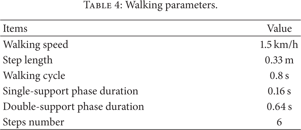
The parameters of the planning trajectory are in Table 4. Biped walking of humanoid robot is composed of two phases: a double-support phase and a single-support phase. We choose the human-like 20% double-supporting phase [23]. Figure 10 is the stick figure of 6-step walking including an initial phase of lowering the centre of gravity (COG) from the ready state and an end phase of lifting COG. We can see that the feet leave and land on the ground with the desired angles. Figure 11 shows the ZMP in X and Y direction, the ZMP is always in the convex hull, and the robot is possible to walk according to the ZMP criterion. Figures 12 and 13 are the positions of ankle and hip in the world coordinate in the sagittal plane.
Walking parameters.

Stick figure of walking in the sagittal plane.
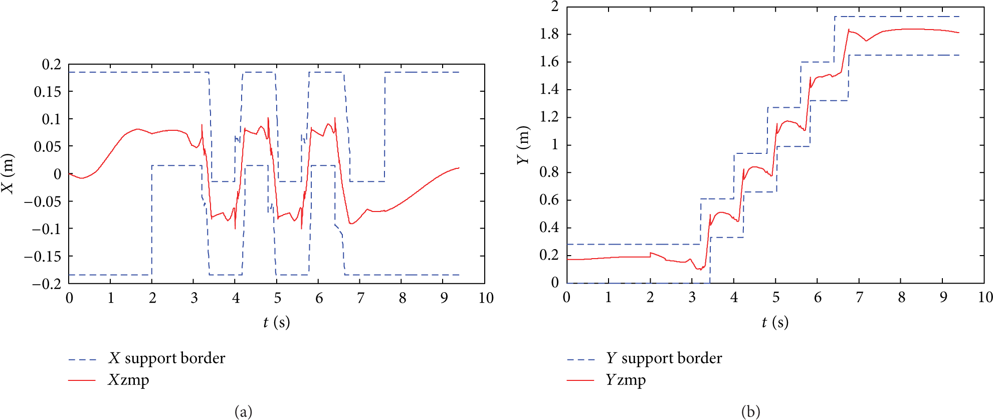
ZMP in X and Y direction.

Ankle movement trajectory in the sagittal plane.
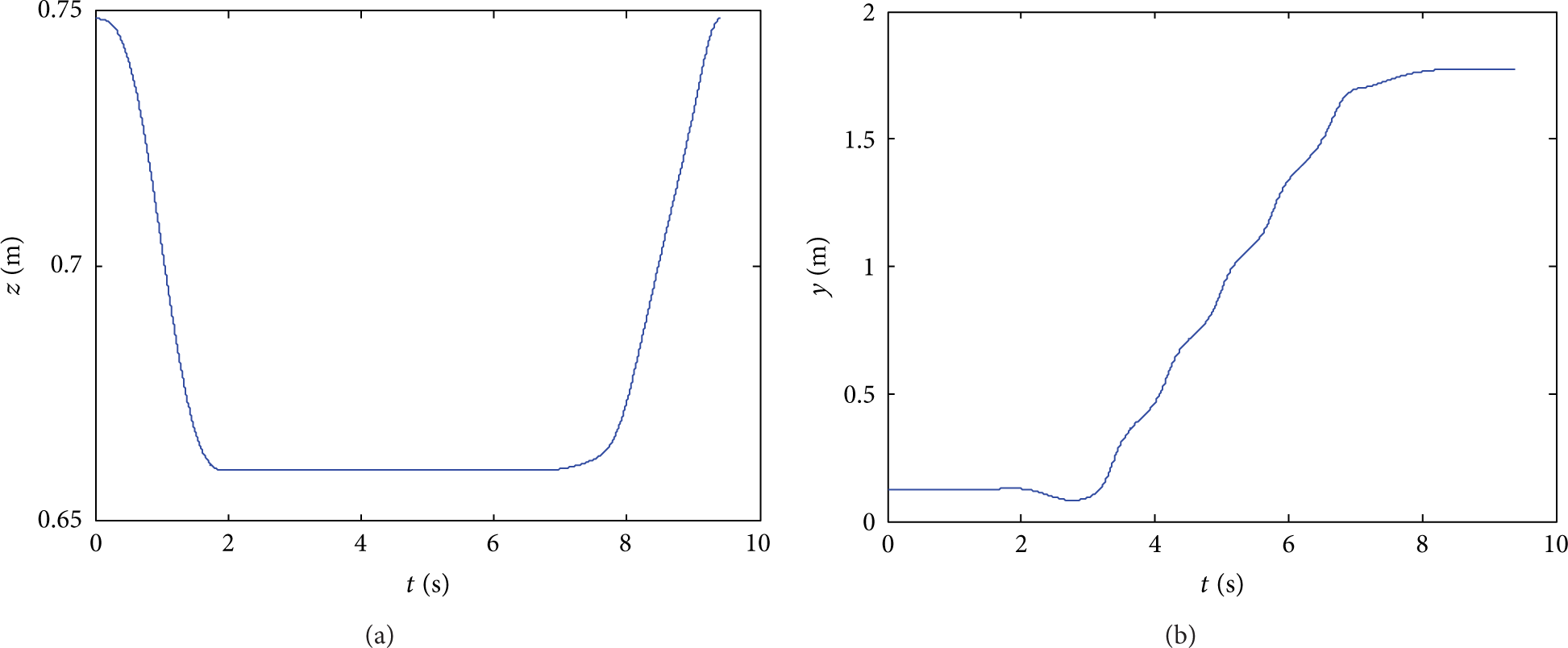
Hip movement trajectory in the sagittal plane.
We conducted walking experiment on the BHR-5 with the speed of 1.5 km/h and the step length of 0.33 m to evaluate the planning method. Figure 14 provides snapshots of walking experiment. The BHR-5 robot walked on the floor stably. In order to overcome the error of dynamics modelling and trajectory tracking and unexpected sudden events (e.g., slightly uneven terrain), we use sensory reflex control [24] to modify the off-line walking pattern real-time.

Snapshots of a video of robot walking.
5.3. Motion Planning and Experiment for Table-Tennis Task
To verify the fast responsive motion capability of BHR-5 robot, we investigated the motion of table-tennis task. As for the process of table-tennis task, the robot firstly grabs the ball images and predicts the subsequent ball trajectory using a series of ball position and velocity with aerodynamics and bounce model, then plans the interception motion, and finally drives the racket to intercept the incoming ball to fly and bounce on/off the table at the opponent's side.
We use θ(t) to indicate the joint angles vector of the arm of BHR-5; that is,

where J+(θ(t)) is the Moore-Penrose pseudo-inverse of J(θ(t)), λ is diagonal weighting matrix, I is the identity matrix, J is the Jacobian matrix of the arm, and the vector ∇ϕ is gradient of a function of joint angles θ(t). The matrix [I − J+(θ(t))J(θ(t))] is a projector in the null space of J(θ(t)). The matrix λ is positive definite to maximize ϕ(θ(t)) and negative definite to minimize ϕ(θ(t)).
And

Once the joint velocity vector
Figure 15 gives the joint trajectories of the arm in a stroke example from the ready state to interception point. Here, the initially ready joint angles of the arm are 45, −45, 90, 80, 90, 0, and 35 degrees, respectively. Figure 16 gives the snapshots from a video of the robot playing table-tennis against a human opponent.

Racket trajectories in world reference frame and joint trajectories for stroke.
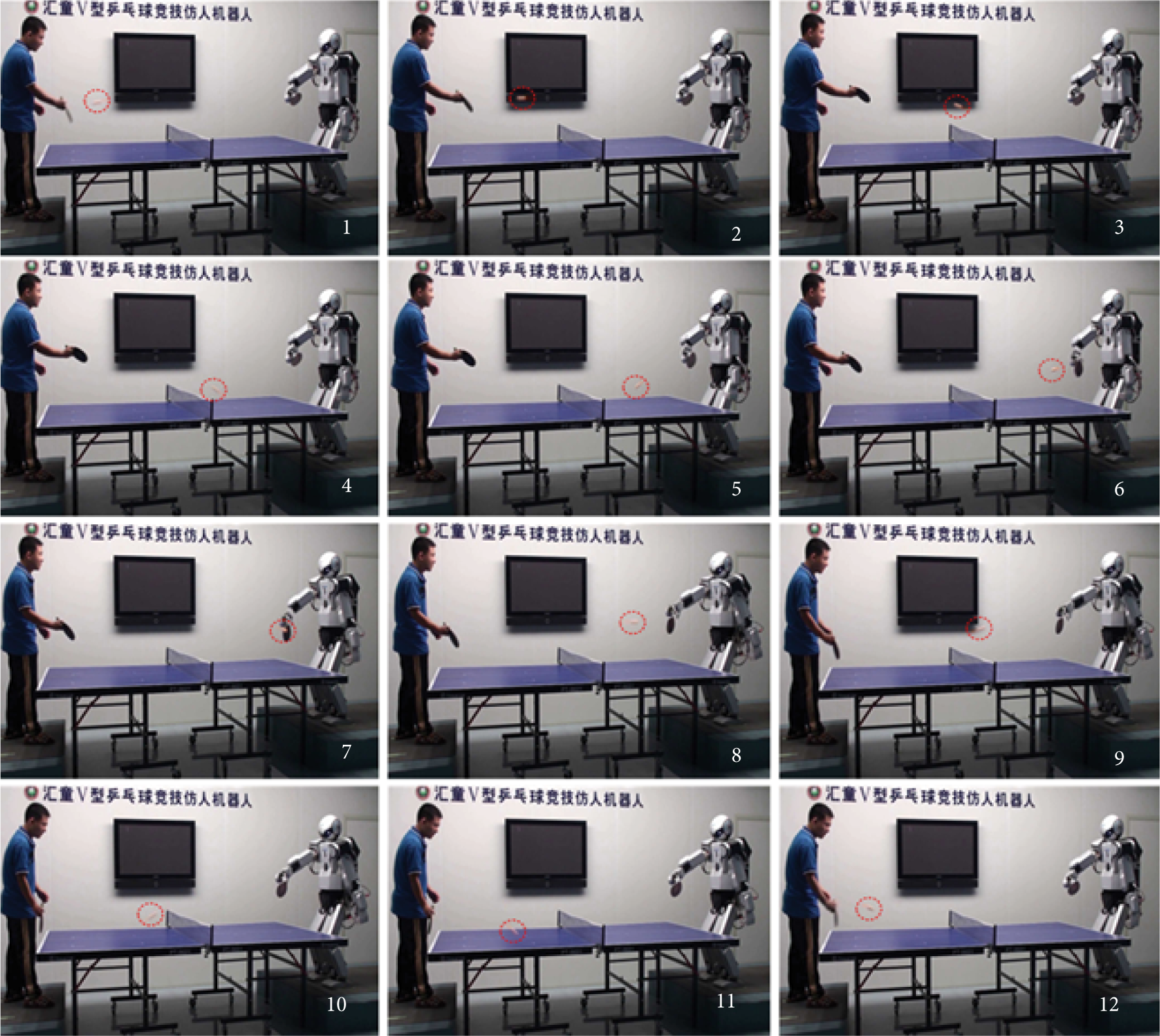
Snapshots of a video of robot playing table-tennis.
It should be pointed out that the control of the lower body and upper body is considered together while playing table-tennis. When the robot moves the right arm to intercept the incoming ball, the controller will compute the counterforce resulting from the moving arm and compensate the counterforce to keep the robot from tipping over through coordinating movement of the lower body with the left arm and the torso.
6. Conclusion
In this paper, the mechanical and control system design of the humanoid robot, BHR-5, is presented. The robot was designed as a robotics platform. The main contributions of this paper are as follows.
An integration design for mechanical structure and the casting manufacturing method was explored to enhance the stiffness and reliability of humanoid robot.
An open control architecture based on concurrent multichannel communication is proposed to reinforce the real-time communication performance and the expansibility of the control system.
Experiments on walking and table-tennis task are made to validate the effectiveness of the design.
Conflict of Interests
The authors declare that there is no conflict of interests regarding the publication of this paper.
Footnotes
Acknowledgments
This work was supported by the National Natural Science Foundation of China under Grants 61320106012, 61375103, 61273348, 61175077, and 60925014; the National High Technology Research and Development Program (863 Project) under Grant 2014AA041602; “111 Project” under Grant B08043; and the Beijing Municipal Science and Technology Project.