
Abstract
In traditional smart grid, data aggregator (DA) and distribution box (DB) send the data collected by sensors to base station (BS) through cellular interface, which is called single-hop communication mode (SCM). In smart grid, different data packets have different delay priorities and the BS cannot satisfy all the delay requirements of different data because of limited resources through SCM. In order to meet the QoS requirements of different priority data, we propose a new scheme: enhanced hybrid communication mode (EHCM), by introducing multihop communication mode (MCM) into this scenario to improve the network's performance by adding another wireless interface on each node. Our scheme EHCM consists of two parts: the intracell data transmission and the cell edge data transmission. In the first part, we propose a solution to choose a relay node according to the node's energy consumption and its residual energy and a solution to forward packets based on its priority and residual lifetime (RLT). In the second part, the tasks of data transmission can be delivered from the congested DB nodes to the adjacent idle ones to provide optimal performance. At last, the simulation shows that our scheme can satisfy the performance requirement of smart grid.
1. Introduction
Now many problems and challenges need to be addressed all around the world, including generation diversification, demand response, energy conservation, and reduction of the industry's overall carbon dioxide. It is evident that we cannot solve these critical issues within the confines of the exiting traditional electricity grid [1].
The traditional electricity grid has low energy conversion efficiency, and only one-third of fuel energy is converted into electricity, without recovering the waste heat. In addition to that, the traditional electricity grid suffers from domino-effect failures easily because of the hierarchical topology of its assets. Because of all these reasons mentioned above, the next-generation electricity grid, named as the “smart grid” or “intelligent grid,” emerges as the times require.
The smart grid is considered as a modern electric power grid infrastructure, which is equipped with improved efficiency, reliability, and safety modern communications infrastructure, through automated control, sensing and metering technologies, and modern energy management techniques and modern communication technologies [2, 3].
In general, the smart grid, which is similar to the traditional electricity grid, can be divided into two parts: transmission grid and distribution grid. The transmission grid involves the high voltage power generated from the power plant and the transmission of the power to the substations through high voltage overhead transmission lines. And the distribution grid involves the low voltage in the substations and the distribution of power to every customer through low voltage power lines. By definition, new capabilities, communication, and data management play important roles in smart grid [4]. Traditional electric power system monitoring and diagnostic systems are typically realized through wired communication. As we all know, the wired monitoring systems require expensive communication cables to be installed and regularly maintained, and, thus, in some circumstances they are not widely implemented today because of their high cost. Hence, wireless communication plays a very significant role in smart grid. Moreover, some wireless communication technologies have been brought into smart grid application environment, such as IEEE 802.11 based wireless LAN, IEEE 802.16 based WiMAX, 3G/4G cellular, and IEEE 802.20 based MobileFi [2].
Recently, many sensors are deployed in various parts of the smart grid for supervisory control, data collections, and meter readings [5]. Traditionally, transmission grid networks are distributed in the places that are far away from humans' residences. If some faults happen in the transmission grid network of traditional power grid, professionals are sent to find what is wrong in the networks and then repair it. However, this is not the case in smart grid. On account of a huge number of sensors in the transmission grid of smart grid, these sensors can collect the relevant information around the high voltage transmission lines and the electrical towers. So once some failure occurs, the data management center (DMC), which is used to analyse data information and deal with the information in smart grid, knows the location of the malfunction; if it is a small fault, the smart grid can take corresponding measures to recover and if it must be repaired by artificial maintenance, professionals can be sent to the failure site directly, which not only saves manpower, but also accelerates the recovery of the smart grid and then it can work properly.
Also, a large number of sensors are installed in the distribution grid network, such as smart meters; they are mainly used to collect the users information. Similarly, these sensors can bring many benefits to both users and power providers. On one hand, users can estimate power price through the information provided by the wireless communication system of distribution grid, and they can reduce the total power consumption when the price is higher. On the other hand, the power providers can provide real-time power price, and it can encourage the users to reduce power consumption during peak period and increase power consumption during nonpeak period, which can surely improve energy efficiency.
In smart grid, some information collected by sensors may carry urgent control messages that must be delivered to the data management center (DMC) at once, while some may be related to the environmental parameters which are less important. So different kinds of information require different ways to be forwarded to the DMC for efficient monitoring and control. In this paper, we focus on the data collection and transmission in distribution grid and smart meter grid.
The rest of the paper is organized as follows. Section 2 introduces the related work, and Section 3 introduces the system model. Then we elaborate the proposed scheme EHCM for QoS requirement in Section 4. Afterwards, the performance of our scheme is shown in Section 5. At last, we conclude our work in Section 6.
2. Related Work
Some previous works have focused on the wireless communication in smart meter grid. In smart meter grid, advanced metering infrastructure (AMI) is expected to facilitate the transmission of meter readings from a smart electricity meter to the utility provider in the other direction. The work [6] explores a cooperative communications approach to improve reliability of AMI networks based on RPL [7], which is called opportunity routing protocol for low power and lossy networks (ORPL). Two problems are investigated in [6]: one is the optimal set of RPL parents that minimizes the cost to reach the sink node and the other one is how to minimize the cost introduced by the forwarding nodes without considering the loss probability between the parent nodes. In ORPL, smart meter nodes select multiple candidate relays to facilitate reliable transmission of smart metering data to the concentrator node. The performance has demonstrated the effectiveness of ORPL in terms of superior packet delivery ratio and lesser number of retransmissions. But this paper only takes the quality of the link into account.
The authors in [8] present a cooperative transmission protocol for meter data collection in smart grid. In this protocol, power consumption demand from the nodes is measured by a smart meter and then transmitted to a meter data management system (MDMS) through the data aggregator unit (DAU) using wireless broadband access. The main idea of this protocol is that the multiple rational communities decide strategically to perform relay transmission for the DAU to transmit meter data to the MDMS according to their individual total cost, such as power cost and transmission cost.
Residual energy, energy capacity, and data priorities are not considered in those two papers, which are significant to performance of the network. And in our paper, we take node's energy and packet priorities into consideration.
The background grid network we study in this paper consists of distribution grid and smart meter grid, which is called Distribution&Smart-Meter grid in this paper, and there are mainly five components: data management center (DMC), base station (BS), smart meter (SM), data aggregator (DA), and distribution box (DB). In smart meter grid, every family has a SM, and a building has a DA. The DA is responsible for gathering the data of the SMs in the same building. The communication medium between DA and SM can be wired or wireless communication. Generally speaking, there exist a DB and dozens of DAs in the same community. Both of DA and DB need to send the collected data to DMC. And we usually put a BS in the center of the network, which is used to forward the data collected by DA and DB to DMC. So the network is similar to cellular network. In general, DA and DB are equipped with cellular interface, such as GPRS, 3G, or LTE, and both of them send collected data to the BS through cellular interface every several minutes, except urgent data. This kind of communication mode is named single-hop. Then BS transmits the data to the DMC of smart grid as shown in Figure 1.
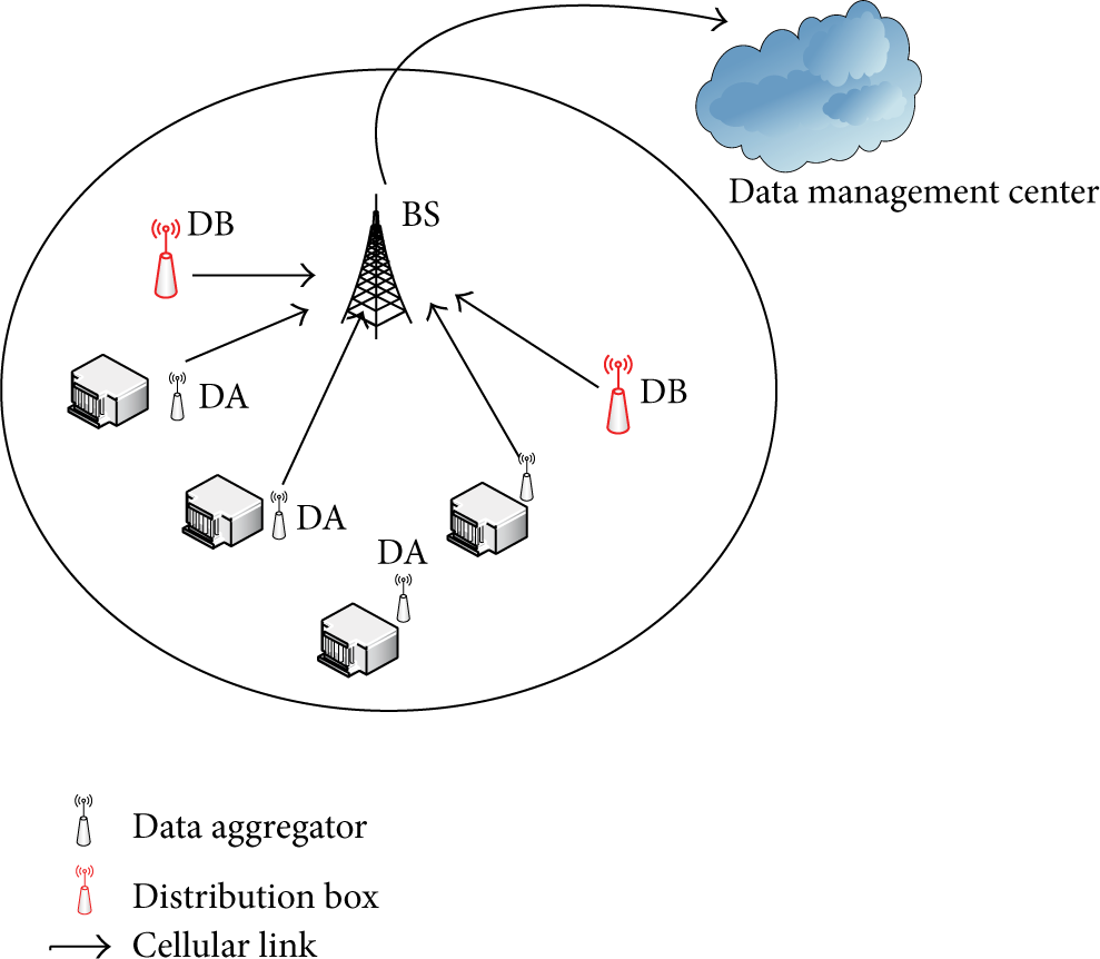
Single-hop communication mode in the Distribution&Smart-Meter grid.
However, the current Distribution&Smart-Meter grid of smart grid suffers from the problem of limited cellular frequency resources. A BS should deal with the communication connection requirements in the circle of three kilometers radius. That is to say, there are thousands of DAs and DBs which will be connected to the BS. There are too many nodes but limited resources. For example, there are some urgent information from DB to be delivered to BS immediately, but BS is in a busy dealing with other transmissions without extra frequency to be assigned for the DB, then the DB has to wait some time or the BS has to cut off some current data transmissions, which will have adverse effect on efficient monitoring and control. In fact, different data have different requirements on delay in smart grid. What should we do to satisfy the delay requirements of different data?
In order to solve the problem resulting from limited resources and to meet the delay requirements of different data flows, we introduce multihop communication into current Distribution&Smart-Meter grid of smart grid by adding another wireless interface on each node (DA or DB), such as WiFi or ZigBee. In our paper [9], we proposed a scheme hybrid communication mode (HCM), in which there are two communication modes: single-hop communication mode (SCM) and multihop communication mode (MCM). Data transmission in a single cell is studied in HCM. Our main idea in paper [9] is that each node decides which communication mode the packet should use based on its priority and residual lifetime (RLT). According to packet's RLT, one node can decide whether it should send it right now through SCM or put it into the corresponding queue and then send it to the next hop (MCM) or drop the packet. In this paper, we study intracell data transmission, we also focus on the cell edge data transmission that the tasks can be delivered from the congested DB nodes to the adjacent idle ones to provide optimal performance. And we name our new scheme enhanced hybrid communication mode (EHCM). To our knowledge, we are the first to introduce multihop into Distribution&Smart-Meter grid for the purpose of QoS requirement.
3. System Model
In the traditional Distribution&Smart-Meter grid of smart grid, every node, DA or DB, is equipped with cellular interface. They deliver data to BS directly through cellular interface. In a general way, DB is equipped with large battery and high power antenna. And DA has less capacity battery compared with DB. In our system model, we add another wireless interface to each node. As a result, the node can communicate with its neighbors through this wireless interface. Therefore, each node may have more than one path to BS through multihop.
In addition, by introducing multihop communication, an original long cellular communication link is broken into two or more shorter other wireless links, which could reduce the required transmission power of each node, and the reduced transmission power could also lead to a lower interference level. So in our system model, data flow has two kinds of communication modes to choose; one is single-hop mode in which data are delivered to BS directly through cellular interface and the other is multihop mode in which data are delivered to BS through multihop by wireless interface and the last hop by cellular interface.
4. Scheme for QoS Requirement
In general, a QoS requirement usually includes specifications like delay, jitter, and connection outage probability. In our paper, we mainly consider delay requirement. It is worth noting that there are different kinds of data collected by different sensors attached on nodes in smart grid. And they have different requirements for delay. In this paper, data flows are divided into three classes according to their priorities: very high priority (VHP), high priority (HP), and common priority (CP). We will recommend how to choose communication mode on the basis of delay requirement of different data later.
By introducing multihop into the Distribution&Smart-Meter grid, every DA can find a path through wireless interface to a suitable DB with large battery which in most cases is located in the same residential quarter with the DA. The general idea of multihop communication in our scheme is to elect DB to be the head cluster, which helps to collect the DAs' data in the same residential quarter and then send all the data to the BS through cellular interface. Additionally, according to [10], if a node wants to transmit data packets to the center sink node, when the length of the path is two hops, the network can perform very well. However, when the length of the path is more than two hops, the routing protocol and the system will be more complex; besides, the control message will waste more frequency bandwidth. The network model in [10] is similar to ours'. They have one thing in common that the data packets in a cell need to be forwarded to the sink node, and in our network model, the DB node can be regarded as a sink node in a small scale cell. So we also limit the length of the path between DA and DB node to be two hops.
In our HCM scheme, each node chooses one of the two communication modes to deliver data: one is to send data to BS directly (SCM) and the other one is to find one of its neighbors to help to forward data to DB, and then DB sends data to BS (MCM). For example, as shown in Figure 2, DA node A needs to transmit data to BS; it chooses MCM to transmit data; that is,

Intracell data transmission in Distribution&Smart-Meter grid.
4.1. Intracell Data Transmission
The first part of intracell data transmission consists of two parts: packet forward and the selection of relay node.
(1) Packet Forward. When data packets reach a node, what should the node do? And now we will present our scheme about packet forward in a node in detail. Each node, DA or DB, owns three priority queues for the three priority data packets: very high priority queue for very high priority data (VHPQ), high priority queue for high priority data (HPQ), and common priority queue for common priority data (CPQ). The priority data in a node may be from other nodes or may be generated by the node itself. Here we define residual lifetime (RLT) of a packet, whose calculation formula is given by

When a data packet is delivered to a node, the node will do the following steps.
Firstly, the node calculates the packet's RLT and compares it with
If the packet's RLT is less than Then, the node puts the data packet into the right priority queue according to its priority. In each queue, when the first packet should be forwarded, the node combines all of the data packets in this queue and then sends them to the next hop.
From the above steps, the packets will be delivered to BS on time or be dropped. And the procedure of packet forward is shown in Figure 3.

Procedure of packet forward.
(2) Selection of Relay Node. As what we have mentioned before, packets generated by DA node will be forwarded to DB along a path which contains DA relay nodes. In this section, we will explain how to find the relays between a DA and a DB.
At first, we introduce a definition of lifetime of the Distribution&Smart-Meter grid. In this paper, the lifetime of the network is the smallest time when a node's battery in this network is used up. To some certain extent, our Distribution&Smart-Meter grid network is a special wireless sensor network (WSN), but our definition of lifetime is different from the one of traditional WSN, which says that the lifetime of WSN is the interval of time, starting with the very first transmission in the wireless network during the setup phase and ending when the percentage of reports from sensor nodes falls below a specific threshold, which is set according to the type of the application [11]. In other words, a WSN lifetime can be defined by a threshold of
In order to prolong the lifetime of Distribution&Smart-Meter grid, we should average the energy consumption on every node; otherwise, some burdened nodes will use up limited battery resources quickly, which will decrease the lifetime of the network.
In the Distribution&Smart-Meter grid, the node, DA or DB, is mostly static, and the link between two nodes is relatively stable. When a DA node has neighbors, which node should be the relay node? In our scheme, we limit that the hop count between DA and DB is no more than two; in other words, any source node needing to forward data to DB at most chooses just one relay node. We choose the relay node according to the neighbor's energy consumption and its residual energy. Considering these two factors is because if we just take energy consumption into account, there is no doubt that we can find the most efficient node, but if it has a little battery remaining, its battery will be used up rapidly, which will have negative impact on the lifetime of the network. On the other hand, if we only consider node's residual energy, perhaps we will find one neighbor that is farther to the DB than this node, which not only is useless for the data transmission, but also wastes precious battery resources.
In this paper, we would like to choose the node that satisfies the following formula to help to forward data:

In some special situations, the link between two adjacent nodes is broken because of some obstacles, or the source node has no neighbors and the source node will deliver the packets to BS directly through cellular interface.
According to the solution mentioned above, we could find the suitable relay node to help forward packets.
4.2. Cell Edge Data Transmission
In fact, we can find a proper route for each data flow in a single cell from the solution in Section 4.1. However, the wireless link is not stable, and it may be broken because of a running trunk or other large obstacles. When the wireless link between BS and DB is disconnected, how does the DB forward its data to the BS? The traditional way is that the DB waits until the link is available. We know that different cells have different information to deal with, and in some circumstances there are so many connection requirements that the BS cannot allocate proper frequency resources in the same time, which will result in some requirements being delayed.
In our real life, a single cell is surrounded by several other cells, and we call them neighboring cells. We know that at the edge of a cell and its neighboring cells, the DB nodes are likely to reach other DB nodes in their neighboring cells. Just like the situation in paper [13], when the one cell is congested, it puts a fix relay node in the cell to help to forward data packets to its neighboring noncongested cell. So we can make use of the link connection between DB nodes in neighboring cell to help to transmit data information.
In this part, we offer a solution in which we can solve the problem of cell edge DBs' data transmission failure, by transferring some connection requirements to its neighboring cells. For example, in Figure 4, when DB1 finds that its BS (BS1) is not available, it performs the following steps until its local BS is available again.
DB1 broadcasts the Find_Agent_Node message to its DB neighbors and records the time The neighbor who receives the message records its own information in the Agent_Node message, except the neighbors in the same cell who will discard the Find_Agent_Node message, and then the DB neighbor in other cells send its Agent_Node message back to DB1. And DB1 records the time DB1 waits to receive the Agent_Node message until time

EHCM in the Distribution&Smart-Meter grid.

Agent_Node message structure.

Find_Agent_Node message structure.
Now the problem is how to choose the appropriate DB neighbor. And we offer a solution that is similar to the way used to choose a proper relay node in Section 4.1. We select the node that satisfies the following formula to help to forward data:
In Figure 4, when the BS1 is busy or the cell1 is congested or the link between DB1 and BS1 is broken, DB1 will find a new path to transmit data; that is,
From the way mentioned above, we can overcome the congestion problems and the problem of broken link at the edge of a cell [13]. So our scheme EHCM could strengthen the stability of the system, and it can also realize the dynamic load balancing by diverting some connection requirements from congested cells to other noncongested cells.
5. Performance of Our Scheme
In this section, we will study the performance of our scheme. We simulate the performance of nodes in two cells. The parameters of simulation scene are shown in Table 1.
Simulation parameters.
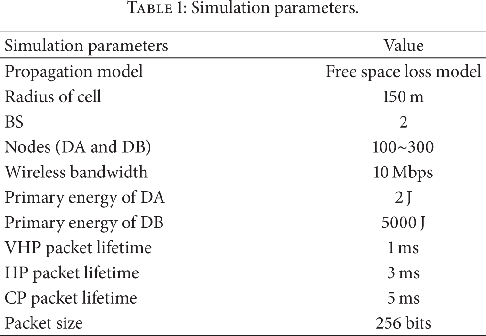
In our simulations, the propagation model is free space loss model. Suppose that the distance of the sender and the receiver is d meters; if the sender sends k bits data to the receiver, then the sender will consume energy as in the following formula:

The following three metrics are used in this study to compare the performance of our scheme EHCM and that of traditional one SCM.
Packet delivery ratio (PDR) is the ratio of the number of packets received to the total number of packets sent. This matrix aims to capture what fraction of packets sent by the sources are actually delivered to the BS on time. Some packets are dropped in the process of transmission because their lifetime is outdated. Through this matrix, we can judge which scheme can meet the QoS requirement better. Lifetime of the network is the shortest time in the network when a node's battery is used up. This metric is particularly significant because lifetime directly affects the performance of the network. Connection reject ratio (CRR) is the ratio of the number of nodes' connection requirements being rejected to the total number of connection requirements. The matrix can be used to evaluate the network service level for users.
Figure 7 shows the PDR performance attained by our scheme EHCM in comparison with the traditional one SCM when nodes change. Result of the experiment shows that with the increasing of the number of the nodes, the two schemes' performances are degrading, but as a whole our scheme shows a better PDR performance.

Packet delivery ratio performance.
That both of the schemes have lower PDR performance is because, with the increase of the node, BS has to deal with more connection requirements from nodes, but frequency resources are limited, which definitely will decrease the probability of a node connecting to BS successfully, leading to a lower PDR performance. Compared with the traditional one, our scheme has a better PDR performance. The reason is that our scheme offers an alternative communication proposal by introducing multihop. When one node cannot connect to the BS through cellular interface, it can have multihop choice to transmit packets. What is more, in the traditional Distribution&Smart-Meter grid network, too many nodes need to connect to the BS with limited resources; the BS cannot deal with all the connection requirements simultaneously, resulting in some requirements failure, and some packets may be dropped directly because of their delay requirements, which will decrease PDR. Moreover, in our scheme, DB nodes can find another DB node in adjacent cells to help to transmit data, while its local BS has no extra frequency resources to allocate, which can definitely increase the PDR performance of the network. That is why SCM's performance curve falls sharply, number of nodes is bigger than that BS can respond simultaneously smooth when the nodes are more than what BS can respond.
It is evident from Figure 8 that our scheme provides longer lifetime in comparison with traditional network. The benefit is significant when there are more nodes. This is intuitive because more nodes signify that one node may have more neighbors; it has more potential relays to help forward packets, which will lead to average energy consumption. Besides, we use DB node to gather and combine all the packets and then deliver them to BS. By this way energy consumption is transferred to the DB node with large battery resources, so other nodes could use less battery to transmit data, which leads to the longer lifetime of the network.

Lifetime performance.
Figure 9 shows the CRR of the network with the increase of the nodes between EHCM and SCM. It is evident from this figure that EHCM has lower CRR than SCM as a whole. At the beginning, when the frequency resource is enough for the connections between nodes and BS, all the connection requirements can be accepted, so the CRR almost is equal to 0.0%. Then, with the increase of the nodes, some connection requirements may be rejected because no frequency resource can be allocated to them. The CRR of SCM rises up more quickly than that of EHCM. That is because in scheme EHCM, DB nodes can help to collect the DAs' data packets and then send them together, which can save a lot of frequency resource. What is more, at the cell edge, DB node in congested cell can find a relay node in noncongested cell to forward data, so this DB node's connection requirement can be accepted, which of course can lower the CRR of the network.

Connection reject ratio performance.
Figure 10 shows the lifetime variation of the network with the change of α, and Figure 11 shows the PDR performance with the change of α when using EHCM scheme. Different α means different energy consumption and residual energy, so that α can affect both the lifetime and the PDR performance of the network. From the simulation result, we cannot say which value is better, but we claim that we can choose a suitable value for α according to the status of the network.

EHCM: lifetime performance with variation of α.

EHCM: packet delivery ratio performance with variation of α.
In summary, compared with SCM, EHCM could improve network's PDR performance and network reliability by introducing multihop communication into this network.
6. Conclusion
In this paper, we analyze the shortcomings of the traditional Distribution&Smart-Meter grid network of smart grid, in which single-hop communication mode is used. To deal with this issue, we propose a new scheme called EHCM, in which a node may have two communication modes to choose according to the packet's delay requirement, by introducing multihop communication mode into the Distribution&Smart-Meter grid network of smart grid. In this scheme, we present a way to choose a relay node based on energy consumption and residual energy in the multihop communication mode, and we also propose a solution to choose a suitable DB agent node in neighboring cells to help to transmit data.
The simulations show that our scheme achieves better PDR performance and longer lifetime than the traditional network. In the future, we plan to study the energy conservation in the Distribution&Smart-Meter grid network. We will try to develop intelligent communication mechanisms based on traffic demand and communication cost in the future research.
Footnotes
Conflict of Interests
The authors declare that there is no conflict of interests regarding the publication of this paper.
Acknowledgments
This research has been sponsored by NSFC 61370151 and the National Science and Technology Support Program of China 2012BAI22B05.