
Abstract
To reduce friction drag with bionic method in a more feasible way, the surface microstructure of bird feather was analyzed attempting to reveal the biologic features responding to skin friction drag reduction. Then comparative bionic surface mimicking bird feather was fabricated through hot-rolling technology for drag reduction. The microriblet film was formed on a PVC substrate through a self-developed hot-rolling equipment. The bionic surface with micron-scale riblets formed spontaneously due to the elastic-plastic deformation of PVC in high temperature and high pressure environment. Comparative experiments between micro-structured bionic surface and smooth surface were performed in a wind tunnel to evaluate the effect of bionic surface on drag reduction, and significant drag reduction efficiency was obtained. Numerical simulation results show that microvortex induced in the solid-gas interface of bionic surface has the effect of shear stress reduction and the small level of an additional pressure drag resulting from pressure distribution deviation on bird feather like surface, hence reducing the skin friction drag significantly. Therefore, with remarkable drag reduction performance and simple fabrication technology, the proposed drag reduction technique shows the promise for practical applications.
1. Introduction
Skin friction drag reduction has been reemphasized in the last decades due to the practical values in engineering applications, including vehicles, aircrafts, ships, and fuel pipelines. Many control methods and technologies have been suggested to reduce the friction drag, but most of them are active ones which require additional power input and complicate the devices [1, 2]. Actually, to explore the underlying drag reduction mechanism and to further reveal the exceptional features of animals in nature would provide us a novel approach for friction drag reduction [3]. Along with the rigorous selection process of evolution, survived living organisms have successfully developed extraordinary abilities to adapt to the environment and offer multiple examples of surfaces that are optimized to control friction. Based on bionics theories, many drag reduction devices such as microstructured bionic surface like riblets and other nonsmooth surfaces have been developed and regarded as a most portable way to be implemented in engineering field [4–6].
Nevertheless, the designed microstructured surface is mostly fabricated with methods, such as PDMS (polydimethylsiloxane) replica [7], vacuum casting [8, 9], and polymer coating [10, 11], which are generally limited to small size and have hampered the implementation in the industries. Actually, an interfacial elastic-plastic deformation theory may provide us a novel and feasible method for the fabrication of microstructured surface [12]. Applications of interfacial elastic-plastic deformation are numerous, especially in mechanical engineering and casting processing. In the last several years, interfacial elastic-plastic deformation in the presence of small-scale structures has been a subject with increasing investigation, and a few applications in microstructured surface fabrication have been reported in the literature [13–15].
In the present study, the surface microstructure of bird feather was analyzed attempting to reveal the biologic features responding to skin friction drag reduction. Then microstructured bionic surface mimicking bird feather was fabricated through hot-rolling technology for drag reduction. Comparative experiments between bionic surface and smooth surface were performed in a wind tunnel to evaluate the effect of bionic surface on drag reduction. The effect mechanism was also numerically analyzed through computational fluid dynamics (CFD).
2. Surface Analysis of Bird Feather
2.1. Sample Preparation of Bird Feather
For sample preparation, flight feather of volant birds was picked with the assistance of Beijing Zoo, and six samples from the above flight feather were gathered. Feather samples were immersed in the mixed liquor of diethyl ether (C2H5OC2H5) and 95% ethanol (C2H5OH) with a ratio of 1: 1 to degrease for one hour for preliminary cleaning. After being further cleaned in the ultrasonic cleaning tank with distilled water for 2 min and natural drying, the feather samples were fixed with the slides for surface analysis.
2.2. Surface Topography Characteristics of Bird Feather
The feather of birds is composed of pinnule, barbule, and pinna rachis. Flight feather and tail feather of bird possess three typical barbules: nodular, hooked, and nonhooked. Hooked barbules and nonhooked barbules engage with each other and would form massy surface to reduce the flight drag. Characteristics of the drag reducing surface of feather are illustrated in Figures 1 and 2.

Sketch map of the alignment and microstructure of flight feather of toucan.

Micrographs of the feather surface structure of toucan obtained by a 3D topography interferometer. (a) Riblet morphology of toucan feather surface; (b) geometry of single riblet.
From the photo shown in Figure 1, we could find the typical riblet structure aligned beside the pinna rachis of toucan flight feather. A similar microstructure could be seen in nearly every flying bird and six typical birds (swan, toucan, flamingo, white dove, marabou stork, and sparrow) are chosen as samples to study the details of feather riblet structure. 3D topography interferometer is used to investigate the microstructure of flight feather and tail feather. Regular microriblets are validated and autosecretory grease could offer sufficient bonding to maintain the riblet structure in case of predation and escape for birds. Detailed geometry of single riblet is shown in Figure 2(b). The measurement depth of single riblet is about 20 μm~30 μm for toucan. From the flight direction of birds and the growth direction of riblets, a certain angle is observed and this indicates that vertical riblets may lead to more significant drag reduction.
For high level of drag reduction, optimization of riblets is often carried out and many scientists have explored the drag reduction level relating to the shape and size of riblets through experiments and simulations. Accordingly, scale of riblets of six typical flight feathers is measured and listed in Table 1. For swan, the depth of riblets is more than 30 μm while it is about 16 μm for sparrow.
Scale of feather microriblets of six typical birds.

The surface microstructure analysis of bird feather may help us to reveal the biologic feathers responding to skin friction reduction and explore the underlying drag reduction mechanism. Furthermore, the fabrication of microstructured bionic surface imitating bird feather with a simple method may provide us a novel approach for drag reduction technologies to be implemented in the industrial applications.
3. Experimental Methods
3.1. Bionic Surface Manufacture
Bionic surface imitating birds' feather was manufactured through hot roll pressing technology (HRPT). Compared to the present bionic surface manufacture technologies PDMS-Si mold and imitation shark skin riblet surface manufacture, the significant advantage of hot roll pressing technology is high level of production efficiency with high accuracy especially for micrometer-size riblets. HRPT induced in this paper could offer high accuracy of riblet geometry (such as depth d, angle α, and distribution density) through the manufactured “microprotrusion” on the mold surface.
The riblet structure is manufactured on the basis of a smooth PVC film. A specified mold is designed with triangular protuberance on the surface. Depth, angle, and distribution density of protuberance are related to the shape and size of riblets formed on the smooth film. After the pressing process in the condition of high temperature and high pressure, elastoplastic deformation of PVC film would lead to the deformation of riblets on the surface and geometry of riblets results from the shape and size of protuberance. Deformation of riblet film through hot roll pressing technology is illustrated in Figure 3.

Sketch figure of the deformation of feather-like riblet film through hot roll pressing technology.
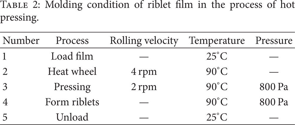
Table 2 listed the molding condition of riblet film in the process of hot pressing. Hot roll loaded 90°C and 800 Pa pressed the smooth film at the rate of 2 rpm and maintain for 3 min. After melt and deformation of PVC film, riblets will be formed on the surface. Synthetic diamond also was used to cut duralumin in the process of mold manufacture for high accuracy of protuberance geometry.
Molding condition of riblet film in the process of hot pressing.
3.2. Drag Reduction Test of Bionic Surface
To evaluate the effect of bionic surface on drag reduction, comparative experiments between bionic surface and smooth surface were performed in a high-speed wind tunnel FD06 shown in Figure 4. FD06 was an intermittent wind tunnel and air was stored in a tank before experiments. High air flow was injected into the tunnel or through the indraft induced by the vacuum tank. As shown in Figure 4, FD06 wind tunnel was composed mainly of air source, honeycomb, supersonic diffuser, subsonic diffuser, and valves. For subsonic experiments (0.3 M~0.9 M), flow velocity would be driven by the atrial pressure. For supersonic experiments, it is necessary to exchange the binary effusion to achieve the flow velocity. Main advantages of FD06 lie in the following points. (1) Dry air was used in the circulation system without heating. (2) High quality of air flow in the testing section of the tunnel was due to the optimized design of tunnel shape. (3) High level of measurement accuracy was achieved with the use of PS18400 electron scanning system and scanning accuracy was ±0.05%.

Schematic diagrams of FD06 wind tunnel.
The skin friction drag was measured in FD06 wind tunnel, as shown in Figure 5. The experimental sample was propped by a central axle through a bolted connection. Force of the sample in x direction was measured through a six-component balance. When the flow flowed through the testing section, force of the sample in x direction composed of friction and pressure drag in the head would be transferred to the balance. Temperature of air flow was measured with the use of senor located in the tunnel wall. Pressure at the end of the experimental sample was measured by pressure tubes. Arrangement of temperature sensor and pressure tubes was shown in Figure 5.

Test section for force measurement in wind tunnel FD06.
Figure 6 showed the structure of experimental sample used in the research. Riblet film manufactured through hot roll pressing technology was covered on the surface of experimental sample. For the comparison between smooth surface and riblet surface, the experimental sample was composed of head, connector, and testing section. Test section was connected with the connector through four-threaded hole. Only the test section was exchanged in the experiments of riblet surface and smooth surface.

Sketch figure of the deformation of feather-like riblet film through hot pressing technology.
The skin friction drag of experimental with riblet film and with smooth surface was measured utilizing the wind tunnel at flow speed ranging from 0.4 M to 0.9 M. The drag reduction percentage of bionic surface compared to smooth surface was defined as
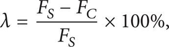
where λ was the drag reduction percentage of bionic surface, F S was the skin friction drag of smooth surface, and F C was skin friction drag of bionic surface.
4. Results and Discussion
4.1. Surface Topography Characteristics of Bionic Surface
The surface topography of riblet film covered on the surface of experimental samples was measured through MicroXAM. As shown in Figure 7, high quality of feather-like riblets aligned on the film surface was observed. A group of geometrical parameters were used to describe regular distributed riblets surface. For maximum drag reduction, length L, depth d, angle α, and attitude angle γ of riblets were used to describe the bionic surface. A series of bionic surfaces with various geometries was designed and used for wind tunnel experiments to investigate the effect of riblet geometry on drag reduction at various flow rates.

Surface topography of bionic surface under MicroXAM. (a) Optical micrograph of the film surface, darker areas representing micron-scale riblets. (b) 3D image of micron-scale riblets. (c) Transverse view of riblets.
As shown in Figure 7, the depth of riblets d was about 40 μm and the angle of riblets was about 60°. For the comparison between smooth surface and bionic surface, smooth surface was manufactured with maximum peak-valley value of surface contour line which was below 120 nm. Due to the modified cutting technology, high level of cutting accuracy was achieved in the process of manufacture of smooth surface and bionic surface. Figure 7 illustrated that distribution of riblets was well distributed with distinct edge of riblets and straightness of bionic surface was manufactured with high quality. Due to the slight wear of cutter, the bottom of bionic surface was coarse.
4.2. Deformation Mechanism Analysis of Bionic Surface
PVC film was elastoplastic material and the deformation in the process of bionic film manufacture would affect the riblet geometry. Accordingly, the level of drag reduction depends on the elastoplastic deformation of PVC film. In this section, we analyze the law of deformation in the process of bionic film manufacture and establish a mathematical model to investigate the impact of elastoplastic deformation on riblet geometry.
Figure 8 illustrated the deformation mechanism analysis of bionic surface. The red line in Figure 8(a) was the riblet geometry after hot roll pressing and before the elastoplastic deformation. Elastic deformation together with plastic deformation resulted in the geometry of bionic surface. After the revert process of elastic deformation of PVC film, black line in Figure 8(a) was the geometry of riblets after elastic deformation. We could find out that the geometry of bionic surface was greatly changed. Riblet depth d was the most significant changed parameter along with the elastic deformation. For better understanding of the relationship between the geometry of bionic surface and the elastic deformation, we carried out a series of experiments to investigate the influence of elastic deformation on riblet depth d and it could be described by the following formula:


Deformation mechanism analysis of bionic surface. (a) Riblets in the process of hot roll pressing technology; (b) mathematical model of bionic surface deformation.
According to the formula, we could find out that the depth of bionic surface would result from the elastic deformation and final depth of riblets was about half of the pressing depth. Riblet geometry resulted from the protuberance of hot roll and the shape and size of cutter decided the protuberance. Final geometry of riblets (αfinal, dfinal) could be calculated through the following formula:

It revealed that the angle of bionic riblets was only related to the angle of cutter regardless of the pressing depth dpressing and the length of the smooth section of cutter. Better understanding of the deformation of bionic surface would be of benefit to achieve high accuracy of riblets for better drag reduction in experiments introduced in the following section.
4.3. Drag Reduction Performance of Bionic Surface
Experiments of the effect of bionic surface on drag reduction were carried out in wind tunnel FD06 with air flow rate ranging from 0.3 M to 0.9 M. To reveal the drag reduction effect, comparative experiments were conducted between smooth surface and bionic surface. Precursor axial force of experimental molds with smooth surface was measured along with Mach number ranging from 0 to 4.0, as shown in Figure 9. Three periods of precursor axial force were observed from the curve: linear period (Area01), steepened period (Area02), and slowly decent period (Area03). Regardless of the shock wave that occurred in the head of experimental molds, comparison experiments between smooth surface and bionic surface were carried out in linear period with a lower component of pressure drag.

Precursor axial force fluctuation along with Mach number ranging from 0 to 4.0.
Figure 10 showed the maximum drag reduction of bionic surface achieved through a series of experiments in wind tunnel FD06. Precursor axial force of experimental molds with smooth surface and three optimized bionic surfaces was measured with the Mach number Ma ranging from 0.4 to 1.15. An obvious drag reduction at the flow rate Ma ranging from 0.4 to 0.9 was observed in the experiments, as shown in Figure 10(a). An average drag reduction rate of 10% in various Ma was achieved and drag reduction rate was proved closely related to the geometry of bionic surface. As shown in Figure 10(b), maximum drag reduction rate when Mach number Ma is below 1.0 could be achieved through the optimization of bionic surface.

The drag reduction efficiency of bionic surface under the changing Mach number Ma ranging from 0.4 to 1.15. (a) Measured precursor axial force of experimental molds with smooth surface and riblet surface. (b) Drag reduction rate through the comparison of smooth surface and riblet surface.
But for supersonic air flow, bionic surface would lead to significant drag increasing result, shown in Figure 10(b). In this paper, only the effect of bionic surface on drag reduction under subsonic air flow (Ma < 1.0) was discussed.
4.4. Effect Mechanism Analysis of Bionic Surface on Drag Reduction
Force analysis on bionic surface was investigated in detail through computational fluid dynamics (CFD). Size of riblets is ranging from several microns to dozens of microns. Physical surface of bionic surface is shown in Figure 11(a). Considering the identical riblets aligned on the surface, single riblet shown in Figure 11(b) is used as the numerical model to represent the bionic surface.

Numerical method of theoretical study of bionic surface on drag reduction. (a) Physical surface; (b) numerical model.
In the calculation study, RANS K-∊ turbulence model is adopted with the consideration of pressure gradient. Details of parameters setting are listed as follows.
Discrete momentum equation: quick; initial condition is standard condition (101325 Pa, 25°C). Convergence standard: 1e − 6 (continuity equation); 1e − 5 (others). Discrete pressure: PRESTO; solver: pressure based; gradient: green-Gauss node based; medium: air.
Simulation results indicated that microvortex induced inside the bionic riblets was the dominant factor resulting in drag reduction. Figure 12 illustrated the induced vortex inside riblet of bionic surface.

Microvortex induced inside riblets of bionic surface.
Viscous force and pressure force were revealed as the main type of forces on bionic surface. On smooth surface, pressure drag was zero due to no microvortical structure. On bionic surface, deviation of static pressure on the front and rear end of the riblets would result in an additional pressure drag beside the reducing viscous drag. Due to the strong shear on smooth surface, wall friction was totally composed of viscous force. Differing from smooth surface, microvortex induced in riblets of bionic surface would lead to a pressure drag component of wall friction besides viscous force.
Microvortex inside riblets of bionic surface at Ma = 0.8 was given in Figure 12 as a sample. Center of microvortex leaned to the front end of riblet and resulted in high pressure zone at this area. When Ma = 0.8, the average line speed of microvortex is about 42.8 m/s~57.0 m/s (estimated). High-speed rotation of microvortex resulted from the energy and momentum transfer at the turbulence boundary layer. Linear speed and wall shearing were greatly degraded compared with smooth surface, which resulted in the viscous drag reduction. Table 3 showed the force on smooth surface and riblet surface while Ma = 0.8. On smooth surface, pressure force was zero without static pressure distribution deviation. And viscous force was about 1.6 × 10⁻² N. So, the total force on smooth surface was equal to viscous force (value was 1.6 × 10⁻² N). While on bionic surface, pressure force was about 2.5 × 10⁻² N due to the static pressure distribution deviation and viscous force was about 13.1 × 10⁻² N which was obviously degraded compared with that on smooth surface. The total force was less than that of smooth surface.
Comparison of forces on smooth surface and bionic surface (×10−2 N).

Figure 13 illustrated the static pressure distribution on bionic riblet at Ma = 0.4. Center pressure of high pressure zone with the value of 19000 Pa was located at the windward side of riblets while low pressure zone with center pressure 4943 Pa was located at the leeward side of riblets. Center pressure of high pressure zone was twice of that of low pressure zone. Accordingly, the pressure drag of single bionic riblet with the value 2.5 × 10⁻² N occurred on the bionic riblet surface at Ma = 0.4. Exponential growth of static pressure drag along with flow rate was observed, as shown in Figure 13(b). For a certain geometry of riblets, exponential growth of static pressure could be described by the following formula:

where y was the center pressure of high pressure zone and x was Mach number. A1, t1, and y0 were the parameters relating to riblet geometry. The curve in Figure 13(b) described the exponential growth for a certain geometry riblet surface. It implied that pressure drag would grow exponentially along with Ma and probably lead to drag increasing result on bionic surface in air flow with higher Ma.
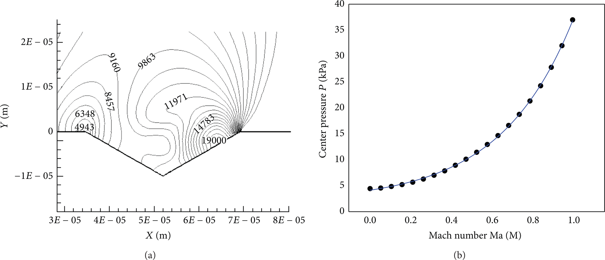
Static pressure distribution inside riblets on bionic surface and the changing center static pressure along with Ma ranging from 0 to 0.9 M. (a) Distribution of static pressure on bionic pressure at Ma = 0.4; (b) changing center pressure inside riblets of bionic surface along with Ma ranging from 0 to 0.9.
To achieve maximum drag reduction, optimization of riblets was conducted on the basis of feather-like bionic surface. As discussed above, pressure drag was the dominant factor resulting in increasing wall friction and hindered a higher level of drag reduction. In our study, a reduced pressure drag through optimization of riblets was the key research topic. Figure 14 illustrated static pressure distribution of four riblet geometries with various depths d and angles α when Ma = 0.35. Geometry of the four riblets is listed (α: angle of riblet; d: depth of riblet):
α = 90°, d = 10 μm (green line);
α = 90°, d = 20 μm (black line);
α = 120°, d = 10 μm (blue line);
α = 120°, d = 20 μm (red line).

Deformation mechanism analysis of bionic surface.
It is indicated from Figure 14 that (1) static pressure distribution depended on the depth d and angle α of riblets; (2) accordingly, pressure drag on the bionic surface would be changed along with the redistribution of static pressure drag; (3) it was meaningful for riblet optimization for a higher level of drag reduction. The pressure drag coefficient fluctuations along with static pressure distribution on bionic surface shown in Figure 14 exhibited an obvious valley with much lower pressure drag. In practical field, it had a very high value for drag reduction and energy saving.
5. Conclusion
To investigate the possibility of reducing friction drag with bionic method in a feasible method, the surface microstructure of birds' feather was analyzed, and microstructure bionic surface mimicking birds' feather was manufactured through hot roll pressing technology. Comparative friction drag test was conducted in wind tunnel FD06 to evaluate the effect of bionic surface on drag reduction. Mechanism of drag reduction on bionic surface was carried out through computational fluid dynamics (CFD). According to the experimental and simulated results, the following three conclusions could be summarized.
Micron-scale riblets with average depth of 10 μm~100 μm and discontinuous smooth surface disperse regularly on the surface of birds' feather, which is a conceivable biological feature for birds' feather to reduce the skin friction drag when flying.
Comparative bionic surface with micron-scale riblets mimicking birds' feather formed spontaneously after the elastoplastic deformation of PVC film in the process of hot roll pressing technology. Mathematic model was established to investigate the relationship between hot pressing roll and the final riblet structure for a high manufacture accuracy of riblets.
Experiments of the effect of bionic surface on drag reduction were carried out in wind tunnel FD06 with air flow rate ranging from 0.3 M to 0.9 M. Comparative experiments were conducted between smooth surface and bionic surface along with Mach number ranging from 0 to 4.0. An obvious drag reduction at the flow rate Ma ranging from 0.4 to 0.9 was observed in the experiments, and the average drag reduction rate of 10% in various Ma was achieved. But for supersonic air flow, bionic surface perhaps leads to significant drag increasing result.
Conflict of Interests
The authors Beibei Feng, Darong Chen, Jiadao Wang, and Xingtuan Yang declare that there is no conflict of interests regarding the publication of this paper.
Footnotes
Acknowledgments
This work was supported by the National Natural Science Foundation of China (no. 31400849) and Specialized Research Fund for the Doctoral Program of Higher Education (no. 20130002120017).