
Abstract
This paper aims at realizing an automatic parking method through a bird's eye view vision system. With this method, vehicles can make robust and real-time detection and recognition of parking spaces. During parking process, the omnidirectional information of the environment can be obtained by using four on-board fisheye cameras around the vehicle, which are the main part of the bird's eye view vision system. In order to achieve this purpose, a polynomial fisheye distortion model is firstly used for camera calibration. An image mosaicking method based on the Levenberg-Marquardt algorithm is used to combine four individual images from fisheye cameras into one omnidirectional bird's eye view image. Secondly, features of the parking spaces are extracted with a Radon transform based method. Finally, double circular trajectory planning and a preview control strategy are utilized to realize autonomous parking. Through experimental analysis, we can see that the proposed method can get effective and robust real-time results in both parking space recognition and automatic parking.
1. Introduction
With the increase in population and economic development of modern society of world, more and more people have cars of their own. The result is that traffic jam is more often than ever before. What is worse, in the increasingly crowded cities, the embarrassment in parking is one of the most difficult problems for drivers. People often have to waste a lot of time on searching for free parking spaces. Sometimes, it is a quite challenging task for drivers to park their cars in a limited space. In this context, the researches on PAS (Parking Assistance Systems) and automatic parking systems have become one of the hotspots in the field of intelligent vehicles. J. D. Power's 2001 Emerging Technology Study shows that over 66% of consumers are likely to purchase parking assistance systems [1].
There are several categories of parking assistance systems [2]. The most prevailing approach now is to use sensor-based techniques, such as laser scanners, ultrasonic radars, and vision sensors. Laser scanners have high stability and accuracy, but they are of high cost and short life and easily affected by the rain and snow weather. Ultrasonic and short range radars are of low cost, long life, and small size. However, their accuracy is low and the detection range is short and, therefore, they cannot be applied in vertical parking mode. Vision sensors, such as cameras, are of low cost as well as long life and their precision is also fairly high. In addition, they can provide real-time vision assists and rich image information to drivers [3]. But vision sensors have poor performance in darkness conditions which have no additional light sources.
As a main trend for parking assistance systems, the vision-based systems are promising and many researchers and companies have developed their systems by using cameras. However, it is very difficult to maneuver vehicles by using one single camera, since the blind spots are inevitable in some complicated conditions, such as narrow valleys and the reverse parking. In this paper, a low-cost bird's eye view vision system is constructed by installing four fisheye cameras around the vehicle to provide the image covering all the vehicle surroundings.
Generally, an automatic parking system consists of three components: path planning including free parking space detection, automatic steering, and braking system used to implement the planned trajectory, and a HMI (Human Machine Interface) which can provide information (such as visual and audio) of the ongoing parking process [4].
To find free parking space, various vision methods are proposed, which can be classified into three categories. Some recognize adjacent vehicles by using the 3D structure of parking lots [5, 6]. Some detect the parking space markings [7, 8]. The others recognize both adjacent vehicles and parking space markings [4, 9]. For example, Fintzel et al. developed a stereovision-based method for parking lots [5]. Xiu et al. developed a monocular vision-based parking lots marking recognition using neural networks [7]. The proposed method belongs to the second category.
Hough transform is often used for detecting the line marking in the parking space [8, 10–12]. However, the performance of Hough transform is not robust to challenges due to the noise, clutter, and variation in illumination and weather conditions in detecting parallel line pairs [13]. Furthermore, in the parking assistance system, the wide-view images of the vehicle surroundings often cover multiple parking spaces. Almost all parking spaces are parallelograms. Nevertheless, under the influence of the noise in image, Hough transform is inefficient in detecting multiple parallelograms simultaneously, compared with the Radon Transform [14, 15]. In this paper, we employ the Radon transform rather than the Hough transform to enhance the robustness and detection accuracy. We also introduce clustering and filtering [16] to improve robustness against the challenges, such as shadows.
The remainder of this paper is organized as follows: Section 2 introduces the bird's eye view vision system based on four fisheye cameras. Section 3 describes the details of parking space detection based on the Radon transform. In Section 4, the methods of path planning and path tracking for automatic parking are introduced. The experiment results implemented in the real scenes are given in Section 5, which substantiated the effectiveness and robustness of the proposed method. Finally, the conclusion is drawn in Section 6.
2. Bird's Eye View Vision System
The Bird's eye view vision used in the proposed system is based on four fisheye cameras with 180-degree field of view around vehicle. The system consists of two phases: calibration and image mosaicking.
2.1. Calibration
The camera imaging model is geometric mapping from three-dimensional space to two-dimensional pixel space. Camera calibration is to find out the parameters of this mapping relation, that is, camera parameters, which can be divided into intrinsic parameters and extrinsic parameters.
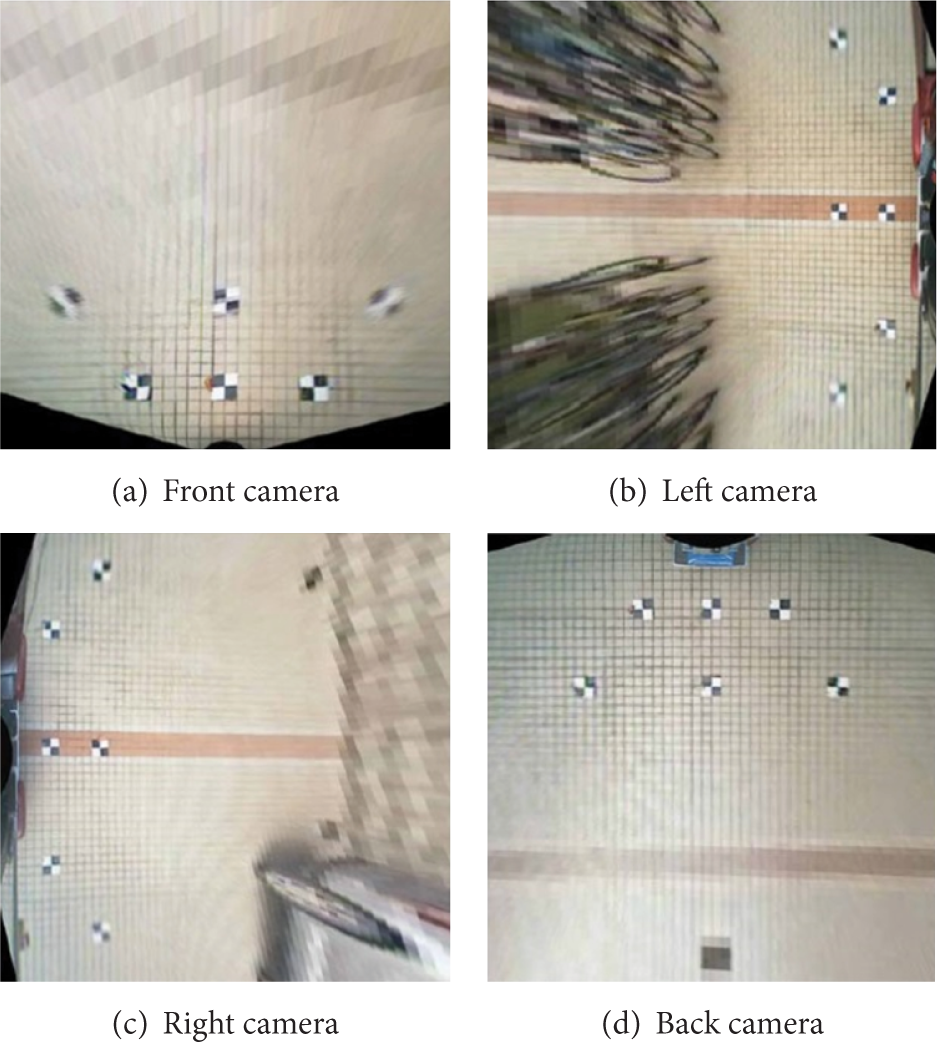
In the real calibration process, we took the flat calibration method proposed by Zhang [17]. The original images captured from the fisheye cameras are distorted; see Figure 1. In order to get high accuracy performance, the following steps are performed. Firstly, the four fisheye cameras are calibrated by using a chess board to obtain their intrinsic parameters and extrinsic parameters, respectively. Secondly, a polynomial distortion model [18] based method is used to correct each camera's distortion. Lastly, according to the inverse perspective mapping (IPM) [19] from the image coordinate to the world coordinate, the undistorted images are transformed to the IPM images in the same ground plane by using the extrinsic parameters. Furthermore, nonlinear Levenberg-Marquardt optimization algorithm [20] is also used to optimize camera parameters.

The calibration images from different cameras.
From experiments we find that the above procedures can obtain comparatively ideal results; the more control points are selected, the more accurate intrinsic parameters and the better results after calibration can be obtained. In this paper, 20 control points are selected on each image and the final results, including calibration effects as well as intrinsic and extrinsic parameters, are, respectively, shown in Figure 2 and Tables 1 and 2.
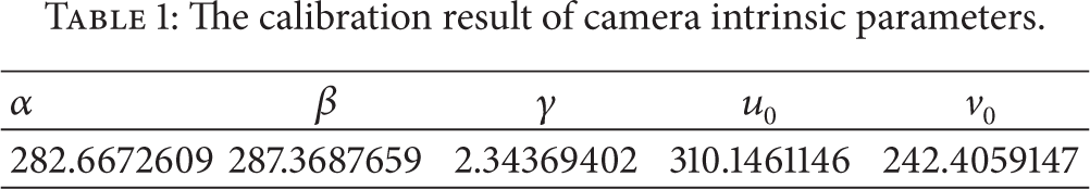
The calibration result of camera intrinsic parameters.
The calibration result of camera distortion coefficients.


The distortion removed images in different cameras.
2.2. Image Mosaicking
In order to obtain the omnidirectional information, the four perspective images are combined into the one synthesized image. We firstly apply vehicle coordinate system-camera coordinate system joint calibration to decide inverse perspective transformation parameters. Then, the Levenberg-Marquardt algorithm [20] is applied to optimize inverse perspective parameters by minimizing the error of feature points. Besides, in order to improve image quality after inverse perspective transformation, the bilinear interpolation algorithm and the white balance procedure are introduced. An example after inverse perspective transformation and an example of the final bird view image are, respectively, shown in Figures 3 and 4.
The calibration result between the cameras and car.

Bird's eye view vision system. Images F f , F l , F r , F b are captured from the front, left, right, and back fisheye cameras mounted on the CyberC3 vehicle. The image in the center is the bird's eye view image synthesized from the four fisheye images.
3. Parking Space Detection
3.1. Overview
Generally, the parking space is often located on one side of the moving vehicle. Therefore, in order to improve the real-time performance of the automatic parking, only the fisheye cameras on the parking space side will be used to detect the free parking space, while all of the cameras are used when the parking spaces are around the car. Subsequently, the IPM (inverse perspective mapping) images are used as the input for the free parking space detection. Furthermore, in this paper, we suppose that roads are flat. Since visual field of fisheye cameras is small, usually within 2 meters of the vehicle, such assumption is generally tenable.
3.2. Radon Transform
The Radon transform is named after the Austrian mathematician Johann Karl August Radon (December 16, 1887–May 25, 1956). Applying the Radon transform in an image I(x,y) for a given set of angles can be regarded as computing the projection of the image along the given angles. The resultant projection R(θ,ρ) is a line integral which is the sum of the intensities of the pixels in each direction. In other words, the liner integral value R(θ,ρ) is the projection of the geometry image along the direction θ, as shown in Figure 5.

Radon transform.
The formulation of the Radon transform is as follows:

where δ is the Dirac Delta function. (θ,ρ) is the parameter space about the Radon space. R(θ,ρ) is the value of Radon space at (θ,ρ) points.
Radon transform and Hough transform both transform the two-dimensional image plane (u,v) to the parameter space, defined by (θ,ρ). Therefore, for both of these two transforms, any line in the image plane has corresponding points in the parameter space.
However, Hough transform quantifies the parameter space to a lot of small lattices, each of which is an accumulator. Points in the image plane will be accumulated in the corresponding small lattices through the parameter transform. After the transform, all the small lattices will be detected, and values in accumulators reflect the condition of the detected line. Therefore, the detection result is easily influenced by noise, such as illumination and shadows, and the detection accuracy and robustness are not very high.
Radon transform is a mapping from the image plane to the parameter space instead of discrete quantified lattices. In Radon space, the corresponding mapping value of the detected line in the image plane is the linear integral value, that is, the projection value of the pixels’ intensities in the image along every single direction θ. The projection value is closely related to the pixels’ intensities of the detected line. Therefore, Radon transform has better noise-tolerance ability and robustness as well as accuracy in detecting lines with gray information, which is the reason why Radon transform is employed to detect the free parking space.
Figure 6 shows the comparison between the image transformation results derived, respectively, from Hough transform and Radon transform. From the comparison, we can conclude that the features in Radon space, that is, light spots in Figure 6(c), are apparently more notable than those in Hough space, and the number of light spots in Radon space is equal to that of lines in the edge image. Therefore, we proposed a method for detecting the free parking space based on this merit.

The contrast between Hough and Radon transform. (a) The edge image with gray information. (b) Hough space. (c) Radon space.
In China, the colored parking line markings are usually either white lines or yellow lines, which have high intensities in the G and B channels of the RGB (Red, Green, and Blue) color model. In the paper, the G channel is used as the gray image for the edge detection. The Canny kernel detector is used to obtain edge image from the gray image. Meanwhile, the intensity values of the edge points in the edge image are preserved. This is very important to make good use of the feature of Radon transform mentioned previously, which ensures the high accuracy and robustness of the proposed system to the noises shadows or obstacles, compared with the system using the Hough transform.
Furthermore, the parking space orientations can be obtained by voting in the angle histogram based on the liner integral value R in Radon space along the θ in the range of [0, 180°); see Figure 7. From the figure we can conclude that since there exists a certain angle between the parking space marking lines, the corresponding angle histogram has two main peaks and the transverse angle between these two peaks just meets the fixed angle relation. Therefore, we can obtain the parking space orientations from the angle histogram.

The angle histogram.
However, with the influence of adjacent vehicle disturbance or noise, such as uneven light or shadows of trees, there will exist several main peaks in one angle histogram, and in the condition with severe noise, the real parking space marking lines may get submerged; see the third row of Figure 7. Therefore, the method talked above should be modified. In this paper, we propose to use the relation between the principal direction and secondary direction of the parking space to superimpose the angle histogram of θ ∈ [0, 180°) on that of θ ∈ [0, 90°) and mark the principal direction and secondary direction. The modified angle histogram is shown in Figure 8. From the figure, we can see that the accuracy and reliability are very high with the modified angle histogram.

The modified angle histogram.
However, the real parking space marking lines do not necessarily follow strict vertical or fixed angle relation and errors usually exist. Therefore, in order not to lose generality, we, respectively, take the neighborhood with a certain range of the principal and secondary directions as regions of interest.
3.3. Features Extraction
Vehicle parking space markings are often constructed with several fixed widths and colored parallel line segment pairs. According to the Radon transform, the lines are mapped to the bright spots (BS) in the Radon space. As shown in Figure 9, they are in one-to-one correspondence.

(a) Lines L1, L2, L3, and L4 are the parking space marking lines in inverse perspective image. (b) P1, P2, P3, and P4 are the bright spot pairs of the lines corresponding in Radon space.
It should be noted that the parallel line segment pairs in the edge image will produce BS pairs in the Radon space. The two BS points in one pair have the same value θ and a fixed width. Based on this feature, a method to detect the center of the BS pair in the Radon space is proposed. Considering the influence of noises, clutters, and vehicles in the edge image, it is necessary to take the area around the BS as the region of interest. The detector structure is shown in Figure 10.
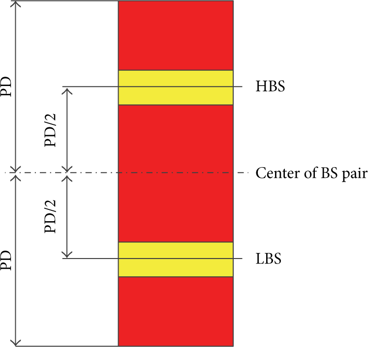
The structure for BS pairs detection. The yellow color is the BS pair in Radon space.
HBS is the high bright spot of the pair and LBS is the low bright spot of the pair. PD is the two BS pixel distances of the fixed width mapped from the line pair:

where V(θ,ρ) is the temporary value of the designed detector. R(θ,ρ) is the line integral value in the Radon space at (θ,ρ). Correspondingly, RHBS, RLBS, R(θ,ρ + PD), R(θ,ρ − PD) are the line integral values in the Radon space, respectively. K s is a factor related by the extent of the difference between RHBS and RLBS. The value is defined as follows:

However, the real lines pair of the parking space markings is not strictly with a certain width. In order to avoid the influence of the line width errors, RHBS and RLBS are taken as the local maximum of their neighborhood near the BS along direction ρ.
Finally, in order to extract the center of the bright spot pair, we limited the temporary value V(θ,ρ) to be in the range of [0, 1] by using the transform as follows:
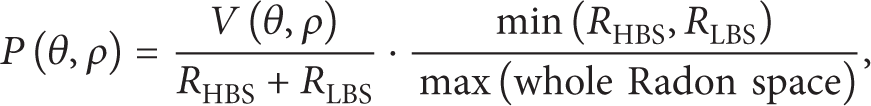
where P(θ,ρ) is probability set of the center about the BS pairs. The higher probability of P(θ,ρ) is, the more likely the parking space exists. With known parking space orientation, the set C can be obtained by series candidate feature points about the possible parking space line segment pairs. The detection result is shown in Figure 11.
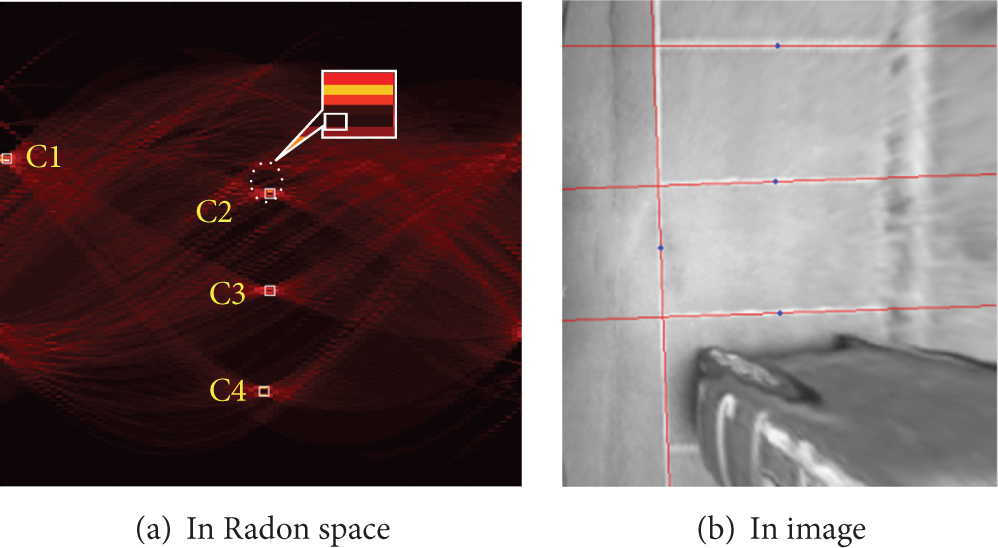
The center detection result of the BS pairs of parking space lines. (a) C1, C2, C3, and C4 are the candidate points detected by the proposed method in Radon space. (b) The red lines are the detection result of the points in image space.
It should be noted that a number of factors, such as the car body lines, shadows, and the wear of the line markings, may often affect the detection accuracy, as shown in Figure 12.

The car body lines of the car interfere with the detection in Radon space. (a) The points marked in yellow area are the interfering points in Radon space. (b) The lines marked in blue area are the interfering lines of the car's body.
In order to get accurate parking space marking lines, some measures to remove the noise factors should be taken.
3.4. Clustering and Filtering
The line segment pairs of the parking space markings are not always strictly in parallel in the real world. To solve this problem, the local maximum along the direction of θ near the candidate points is performed. Furthermore, although almost candidate points of the set C belong to the parking space line segments, it cannot deal with the challenges due to shadows or the body lines of the car parked; see Figure 12. Therefore, we perform the K-means cluster algorithm first and then filter the intervening points of the set C by using the parking space geometry shape features. Finally, the center points of the BS about the parking lines can be fixed in the set C.
The final detection result is shown in Figure 13, which shows that the proposed method of designed line detector, clustering, and filtering can effectively and accurately detect the parking spaces in various scenes. Furthermore, the proposed method demonstrates the high robustness against the challenges, such as shadows.
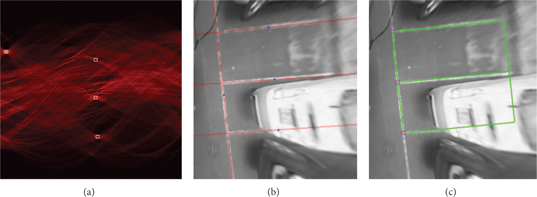
Result of parking space detection after clustering and filtering. (a) The detected points are the center of the BS pairs about the parking space marking lines in Radon space. (b) The red lines are the result of the detected points mapped to image coordinate. (c) The green rectangles are parking space.
Figure 14 shows the proposed methods take good performance in different scenes for parking space detection.

The proposed method detection experiments of the parking space in different scenes.
3.5. Empty Parking Space Extraction
The method talked above detects both the empty parking spaces and occupied parking spaces. Since, when parking cars, we are usually concerned with empty parking spaces, empty parking spaces should be extracted.
After parking space detection, the principal direction can be used to have image rotation calibration and the effect after calibration is shown in Figure 15.
Principal direction correction.
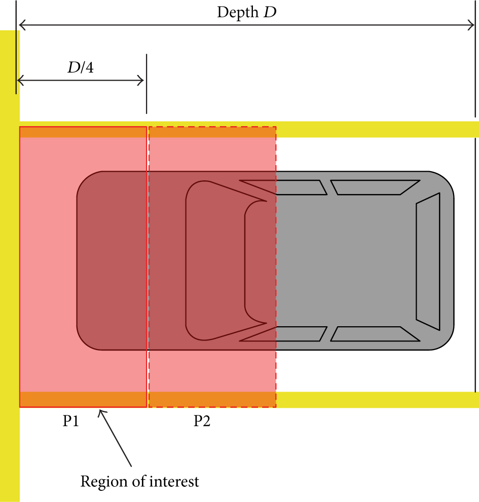
After image angle calibration, a certain parking space is taken as the research object. Considering accuracy, robustness, and real-time performance, a quarter of the parking space depth is taken as the region of interest; see Figure 16, and the image area of the region of interest is taken as the feature to decide whether a certain parking space is empty or occupied. The rate of the image area (image pixel numbers) to the area of regions of interest (total pixel numbers in region of interest) P1 and P2 is, respectively, defined as S1 and S2, and a high threshold T H and average threshold T M are set. Firstly, compare S1 with T H . If S1⩾T H , consider this parking space as occupied and go to the next parking space. Otherwise, go to the region of interest P2. Secondly, compare S2 with T H . If S2⩾T H , consider this parking space as occupied and go to the next parking space. Otherwise, calculate S m :

Finally, compare S m with T m . If S m > T m , consider this parking space as occupied, and go to the next parking space. Otherwise, consider this parking space as empty.
The region of interest for recognizing the free space.
4. Path Planning and Path Tracking
In this section, the method of path planning and tracking for vertical automatic parking based on the detection results of the free parking space is described.
4.1. Path Planning
Given what has been talked about previously, it is able to get the position information of the parking space. In this situation, a path planning method is needed for the automatic parking. Up to now, there are two path planning methods which are usually used for parking vehicles, that is, single circular trajectory based path planning method and double circular trajectory based path planning method.
The traditional single circular trajectory based path planning method can be divided into three parts, that is, a straight line for the first part, a circular arc for the second part, and another straight line for the third part. However, this method is always constrained by the size of parking spaces, obstacles, space for parking, and so forth, which will lead to failure of automatic parking. Considering all these defects, the traditional double circular trajectory based path planning method has done a lot of improvement. Yet, this method does not take into account the initial position of cars relative to the target parking space. As a result, this method cannot plan a parking trajectory which can be easily controlled. Under this circumstance, we proposed an improved double circular trajectory based path planning method.
Figure 17 shows the details of this method. XOY coordinate is the world coordinate. P1 and P2 are the entrance guidance points obtained from the parking space detection result in the image coordinate by using the inverse perspective mapping. Correspondingly, WD is the parking space depth. The planned path is based on a double circular trajectory, which has three switch points A, B, and C.
Before point A, drive the car along the straight path till it reaches point A.
In the circular arc AB, drive the car with a certain steering angle for the circular motion.
In arc BC, reverse the car in another certain steering angle for the circular motion till reaching point C.
After point C, drive the car along the straight path.

Parking path based on a double circular trajectory.
In order to improve the parking performance in a continuous operation, it is very important to minimize the turning radius to fit the parking space. However, the smaller the turning radius is, the more likely the car may hit the neighboring vehicles. Therefore, the turning radius is calculated with the constraint of the geometry relation as shown in Figure 18:
where, L is the wheel base of the car, w is the width of the car, and ϕmax is the maximal steering wheel angle. R1 is turning radius in the first turn. Here, it is the minimum turning radius of the vehicle. R2 is the turning radius of the second turn. d is the distance from the car coordinate center to the lines between parking space entrance guidance points. D_road indicates the whole space of the car used during the parking procedure. According to the above formulations, it is able to get the position of the switch points and steering wheel angle α by setting an appropriate D_road.
Geometry relation in path planning. (a) Path planning. (b) The minimum turning radius in R2.
4.2. Path Tracking
Path tracking is mainly to solve the problem how to determine the steering wheel angle and speed at each time for the vehicle to follow the planned path. Generally, the speed of the vehicle is often low during the whole parking process. Therefore, we only consider tracking of the steering wheel angle of vehicle.
We employ the preview follow based on the PID (proportional-integral-derivative) strategy since it is simple and efficient for the vehicle control [21].
The principle is shown in Figure 19. The preview point is taken in front of the vehicle with a certain distance. Subsequently, the distance between the preview point and the target path is taken as the input of the PID controller. However, such method often has slow response and difficulties to control accurately when the curvature of the path is large. To overcome this problem, we proposed an improved method of the PD controller based on the feed forward for the vehicle control.

Improved method for circular motion.
Preview point A uses a typical preview with straight line method to get minimum distance e1 between point A and the target circular path. Subsequently, the preview point B is estimated by DR (Dead Reckoning) in the current pose of the vehicle in circles. Correspondingly, e2 is the distance using the same method with e1.
The feed forward parameter is the steering wheel angle ϕ calculated by the previous formulation. So the final steering wheel angle is calculated as follows:

where the e i 1 is the e1 in the moment of i and the e i 2 is the e2 in the moment of i. K p and K d are parameters of PD controller.
5. Experiments and Results
5.1. Experimental Platform
The proposed system was implemented in our experimental platform based on the CyberC3 [22, 23], which has four fisheye cameras mounted around the vehicle. The angle encoder for measuring the steering wheel angle and the odometer encoder are also installed on the platform. Details are shown in Figure 20.

The CyberC3 vehicle mounted four fisheye cameras system images C f , C r , C l , and C b are the fisheye cameras mounted in the front, right side, left side, and back of the car.
5.2. Detection Accuracy
Figure 21 shows the proposed method based on the Radon transform is more robust than those based on the Hough transform in the noisy environment. Figure 22 shows that the Radon transforms can obtain a good performance in detecting multiple parking spaces simultaneously. This was also verified in [14] for detecting for rectangles and [13] for parallelograms.

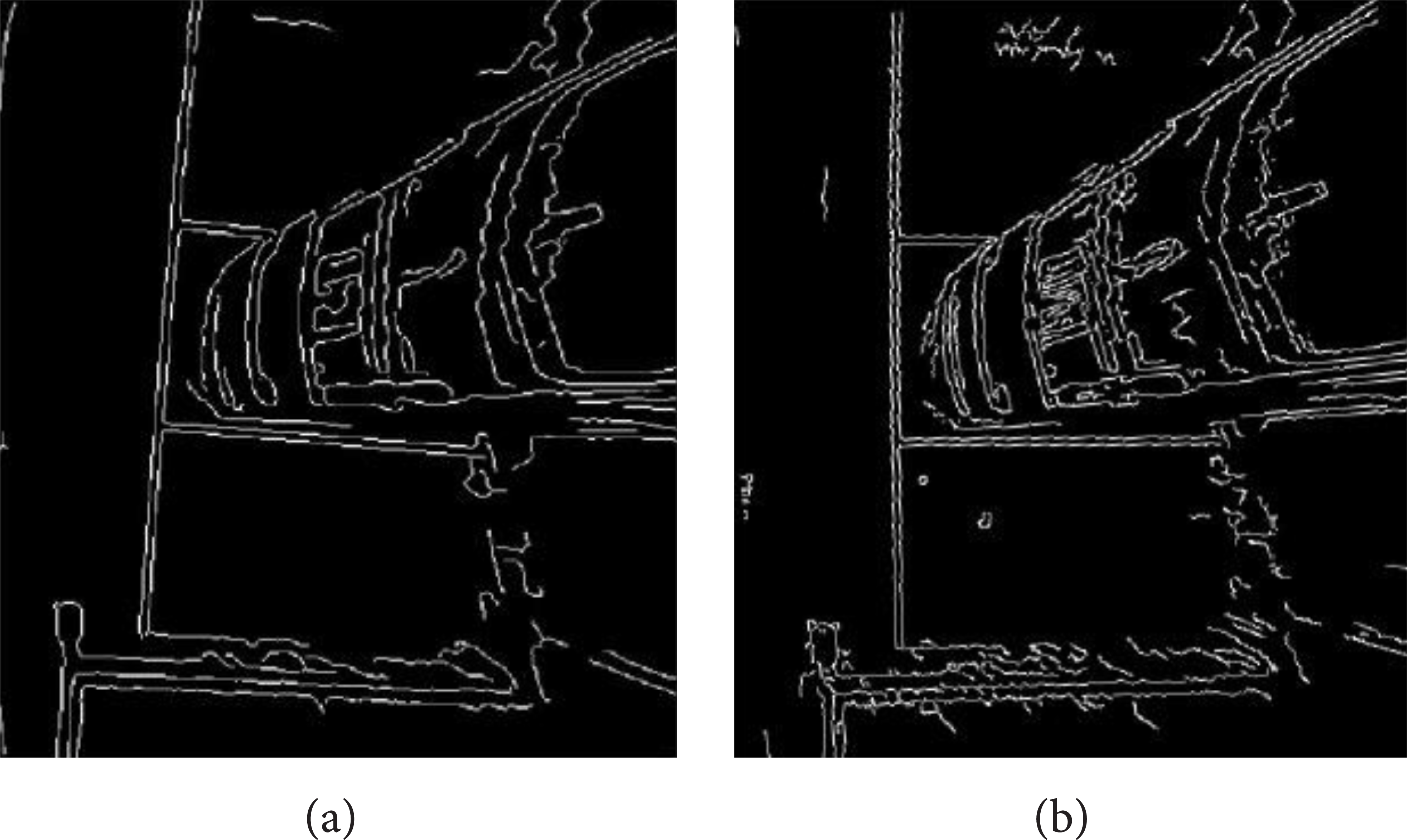
The robustness of Radon space in detecting parking space is better than Hough transform in the same conditions, including the same detector, clustering, and filtering. (a) The ground cracks noise in the edge image affects detection points in Hough space. (b) The noise has no influence on detecting space in Radon space.
The performance of Radon transform has more accuracy than Hough transform in the same conditions, including the same detector, clustering, and filtering. (a) The detection of parking spaces in Hough space. (b) The detection of parking space in Radon space.
In the experiments, there were totally 2626 frames used to compare the performance of the proposed method against those based on the Hough space under the same condition. The comparison results are shown in Table 3.
Comparing the parking space detection of the proposed method with Hough space.

The precision and recall used in Table 3 are computed as follows:

where the true positive is the frequency of the correct detections of the parking spaces. The false positive is the frequency of false detections and the false negative is the frequency of the missing detections.
From the experimental results we can see that the proposed method performs robustly and accurately despite of the challenges due to shadows and other vehicles.
5.3. Empty Parking Space Extraction
Figure 23 is the experiment result of empty parking space extraction. In this figure, the red rectangles are occupied parking spaces while the green ones indicate empty parking spaces.

Experiment result of free parking space.
In the experiment of empty parking space extraction, we took 327 images of different environments and the quantitative evaluation results are shown in Table 4. In this table, false positive detection number means the number of wrongly indicated parking slots that are not empty.
The statistical result of empty parking space extraction.

Based on the experiment results, we can see that the empty parking space extraction method, which is based on regions of interest, has very high accuracy.
5.4. Automatic Parking Simulation Experiment
In order to evaluate the proposed path planning and path tracking method, a simulation of the path planning is executed in MATLAB. The scale size is determined by the inverse perspective image. The coordinate is transformed to the inverse perspective image coordinates. One pixel represents 2 cm in the real world coordinate. Furthermore, the proposed path tracking simulation is executed in TORCS (The Open Racing Car Simulator).
From the simulation results (see Figure 24), it can be found that the proposed path planning is a good trajectory for automatic parking. Furthermore, the improved method of path tracking is more fast and accurate than traditional method (Pure PID method).

The simulation result of the proposed method for path planning and path tracking.
6. Conclusion
In this paper, a low-cost bird's eye view vision assistance system with four fisheye cameras has been developed, which can provide the surrounding view of the host vehicle. The system can rectify the images captured by the fisheye cameras and mosaic them into a bird's eye view image in real-time. Furthermore, a method for detecting the free parking space has been proposed based on the Radon transform. The detector for the center of bright point pairs is completed in the Radon space. By using the clustering and filtering based on the shape features of the parking space, we can alleviate the effects of noises effectively. In particular, we compared the performance of the proposed system against those based on the Hough transform in the experiments. The experimental results show that the proposed method has more accuracy and robustness in detecting the free parking space. Finally, a simulation of the path planning and path tracking is executed to evaluate the proposed method for automatic parking.
Conflict of Interests
The authors declare that there is no conflict of interests regarding the publication of this paper.
Footnotes
Acknowledgments
This work was supported by the General Program of National Natural Science Foundation of China (61174178/51178268), the Major Research Plan of National Natural Science Foundation of China (91120018/91220301), and National Magnetic Confinement Fusion Science Program (2012GB102002).