
Abstract
An overview of the most important development stages of floating point absorber wave energy converters is presented. At a given location, the wave energy resource has to be first assessed for varying seasons. The mechanisms used to convert wave energy to usable energy vary for different wave energy conversion systems. The power output of the generator will have variations due to varying incident waves. The wave structure-interaction leads to modifications in the incident waves; thus, the power output is also affected. The device has to be stable enough to prevent itself from capsizing. The point absorber will give optimum performance when the incident wave frequencies correspond to the natural frequency of the device. The methods for calculating natural frequencies for pitching and heaving systems are presented. Mooring systems maintain the point absorber at the desired location. Various mooring configurations as well as the most commonly used materials for mooring lines are discussed. An overview of scaled modelling is also presented.
1. Introduction
Ocean waves are one of the most promising sources of renewable energy with an estimated potential of 2 TW around the world [1]. Waves are created by a generating force. The common generating forces are bodies moving on or near the surface of the ocean, winds, seismic disturbances, and waves generated by the lunar and solar gravitational fields. The most common types of waves considered for engineering analysis are those created by the wind or swells [2]. Winds transfer energy to waves from the direct push of the wind on the upwind faces of the waves, from frictional drag between the air and the sea surface, due to pressure differences in the air just above the water.
Point absorbers are floating wave energy converters (WEC's) whose dimensions are much smaller than the wavelength. They oscillate with the ocean waves with one or more degrees of freedom. A point absorber is capable of absorbing wave energy from a wave front greater than the physical dimensions of the device itself [3]. A feasibility study of the ocean wave energy resource in a given location is essential for design of WEC's [4]. The designs of offshore marine structures require a thorough understanding of the ocean characteristics and behavior [5]. A study of the ocean wave characteristics allows the engineer to assess the energy available in the waves at a particular site and to design an appropriate WEC to get optimum performance. Wave energy converter devices could be located offshore or inshore. The important parameters to describe waves are the wavelength, wave height, period, and the water depth over which they are propagating [6]. There are some well researched theories which are able to predict the wave characteristics at different water depths. However, these theories are approximations and the real ocean wave characteristics can vary largely [2].
A point absorber WEC utilizes the motion of the surface waves to generate electricity. Wave energy conversion process can be basically defined as the force or torque produced in a WEC by an incident wave that causes relative motion between an absorber and a reaction point [7]. A point absorber responds to the wave action and produces mechanical work [4]. Any structure present in the path of the waves will lead to modification of the waves by altering the fluid flow and the associated flow field [8]. The wave-structure interaction of the point absorber and the waves need to be studied in order to be able to judge the motion response of the device. The wave-structure interactions greatly affect the wave energy conversion [2], as well as the stability, natural frequency, and the mooring of the device.
A point absorber will experience many external loads, (such as winds, waves, and currents) and internal loads (such as shifting masses in the device). It should be stable enough to be able to withstand these loads and prevent itself from turning over [9, 10]. The response of a point absorber depends on the frequency of the oscillating waves. The motions of the point absorber are more pronounced with maximum power absorption when the wave frequencies correspond to the natural frequency of the device [11]. Normally, for point absorbers, due to their small size, the band of wave frequencies for which the WEC gives optimum performance is very low. Floating WECs need to have good power capture from the incident waves for most common frequencies [12]. In order to prevent the point absorber from drifting away from the desired location, the device is moored using mooring systems. A point absorber and its mooring system face large oscillatory forces [13, 14].
Model testing provides valuable information which can be used to predict how a prototype would behave under similar conditions. Scaled modeling should ensure that the model correctly represents the prototype [8]. A pilot device is a scaled down model of the final proposed device. Pilot device testing confirms the operational parameters that are predicted in scaled model testing. The results from pilot tests can be used to make changes if required in the final device.
This paper presents an overview of the development stages involved in planning a floating point absorber WEC. The parameters mentioned above are presented in Figure 1. Even though it is not a complete list, all these factors at a minimum should be researched on before implementing a floating point absorber WEC. A complete review/classification of WECs is presented by Falcão [15]. Some other important factors that should be considered in the design (but not included in this paper) are the life cycle analysis, reliability and cost, factor of safety, fire protection, construction, maintenance, and survivability. Guidelines for design and operation of WECs that covered such details are given in [16]. It should be kept in mind that working in the ocean is both dangerous and expensive. Thus, it is more cost effective to sacrifice some wave energy conversion efficiency to ensure the safety and survivability of the system [2].

Summary of steps that should be considered when planning a floating point absorber WEC.
2. Ocean Waves
2.1. Wave Energy Resource
Energy harnessing involves determining the activities in the target society that requires energy, determining the available energy resources, and a plan to match the demand and the supply [17]. A feasibility study of a WEC requires a detailed spatial and temporal distribution of wave energy and wave frequency in the chosen area of installation. The variations of wave characteristics on a yearly basis are also important [4]. The ocean wave characteristics and thus the wave energy have regional and seasonal variations [18]. Figure 2 shows a 10-year power estimate in kW/m. It can be seen that regions between 40° and 60° latitude have higher average yearly wave energy compared to other regions. The wave energy is also different for different seasons (shown for January and July) [19]. Another important aspect in selecting prospective farm sites is wave refraction due to the concentration of wave energy in certain inshore areas as a result of the irregular bathymetry [20, 21]. Higher energy is generally available in deeper water compared to shallow water where the waves get affected by the seabed, leading to refraction, shoaling, and diffraction [22–24].

Variation in mean monthly and (c) annual wave power against latitude [19].
Waves are a regular source of power and can be predicted in advance. It has the highest energy density among all other renewable energy sources [1]. The swell, which has a high relative energy, has a relatively great length and a small wave height and is the most frequently observed wave and, as such, is of primary interest in wave energy conversion [2].
The energy loss in the waves occurs due to turbulence in water motion as a result of breaking waves. Some energy is also lost due to viscous effects. If no energy is lost from the waves, they would continuously grow for as long as the wind fed energy. However, this is not possible. Once waves reach their height limit due to breaking and if more energy from the wind is still available, the energy gain is reflected in the growth of the wavelength [25]. The energy gains and losses of the ocean waves (for deep water) can be represented in an energy balance. The energy balance, (1), represents the physical source functions of the generation of waves by wind and the energy dissipation due to white-capping and nonlinear wave interactions [26, 27]

where Sin represents wave generation by wind, Snonlin represents the nonlinear energy transfer by wave-wave interactions, and Sdissip is the energy dissipation by wave breaking and viscous effects [27]. For steep waves, wave-wave interactions transfer energy from one wave component to another and may couple the phases of the wave components involved. These processes are mostly quadruplet wave-wave interactions and white-capping in deep water [26]. When the energy balance is reached, the sea state can be stated as a fully arisen sea [25]. The energy gains and losses of the whole ocean can also be represented in an ocean energy balance [28].
Surface water waves have energy associated with them, kinetic energy of the water particles motion and gravitational potential energy associated with vertical position of water from the mean level [29]. Higher energy is generally available in deep water waves compared to shallow water where the waves begin to feel the bottom [22, 23]. In deep water, the approximate expression for wave power transmitted per unit width is given as [30]

where H s is significant wave height, T e is the energy period defined in terms of spectral moments, ρ is seawater density, and g is the acceleration due to gravity.
Site assessments are made by monitoring the wave climate over a significant period to determine the resource contained at various sea states and seasons [19]. At least 15 months of wave data should be collected before conclusions about the available resource at a particular site could be made. The first 12 months of data measurement will show the wave data over different seasons. The extra 3 months will show the repeatability of the data.
The wave parameters are usually recorded as a discrete time series [19]. The energy contained in the surface waves can be represented by a wave spectrum, which gives the energy distribution of the waves in a finite area at a given location [27]. Figure 3 shows a schematic of the different ways of representing the wave spectra.

Schematic representation of the wave spectra [93].
2.2. Wave Characteristics
Ocean waves are generally a combination of several different wave types. Different wind conditions generate waves with different wavelengths, frequencies and height, and sometimes different wave profiles [5]. Changes in weather patterns also affect the wave climate. Since waves of different wave lengths travel at different speeds, waves of different sizes combine and recombine in a constantly changing interference pattern [25]. Ocean waves can be said to be the superposition of a large number of sinusoids going in different directions [6]. Ideally, the water particles for both deep water and shallow water waves undergo orbital motion. The orbit is circular in deep water waves but elliptical in shallow water waves with the major axis in the horizontal direction. The kinetic energy and the size of the orbits are larger near the surface and reduce with increasing water depth [31, 32]. For deep water waves, the effect of the surface wave motion is reduced to about 4.3% of its surface amplitude at a depth of approximately half the wavelength [31]. In shallow water, the effect of surface waves is felt till the bottom [33].
The wave height and period are two measurable properties of ocean surface waves. These properties are measured by using wave gauges or estimated by sight. The observed wave height corresponds more to the average of the one-third highest waves rather than to the average wave height [2]. Measurement techniques can be divided into in situtechniques (instruments deployed in the water such as wave buoys, wave poles, echo-sounders, pressure transducers, and current meters) and remote-sensing techniques (instruments deployed at some distance above the water such as radar) [25]. In practice, wave height, period, and water depth are given by field measurements but the wave length is usually calculated by a dispersion equation given by a wave theory [34].
Waves can be described in great detail with mathematical theory using basic hydrodynamic laws. Estimates of the water surface motion, water particle velocities, and the wave induced pressure in the water can be made with theoretical models [25]. However, it should be noted that there is no mathematical theory that exactly describes the behavior of the ocean waves [2]. Some of the theories used to calculate the wave characteristics are the linear wave theory (or airy theory), Eckart's approximation, Olsen's approximation, Hunts approximation, Nielsen's approximations, Vanezians approximation, and Wu and Thornton's approximation. These approximations, however, ignore the effects of wave height and current. Wave height and current have significant effects on the wavelength for a given period [35]. Some theories that include the wave heights are Fenton theory, Hedges approximations, and Stokes higher order theories. Fenton theory also considers the wave currents [36].
The wave crests in the ocean are slightly sharper and the troughs are slightly flatter [25]. They are not always pure sinusoids. The amplitude variations in an irregular sea induce a slow drift force which is not predicted by the linear wave theory, and thus shapes of water particle orbits are not fully closed [5]. Waves break when the wave crest gets very steep and exceeds the wavelength by a ratio of 1: 7. As has been shown by Stoke's, the internal crest angle is less than 120° for a breaking wave [37, 38]. Breaking waves lose wave energy due to turbulence and friction; thus, broken waves are not of major interest in wave energy conversion [2]. The knowledge of wave characteristics can be used as a basis for designing point absorber WECs. The structural design can be carried out by using the design wave approach or design to a statistical wave description approach. The design wave approach uses the maximum wave height that will occur in a given time interval for a given range of wave periods. Thus, the structure is designed to avoid damages in the worst operating conditions. In the statistical wave approach, the incident waves on the device are expressed in a probability distribution, which describes the occurrence of waves for specified wave height, period, and direction [5].
3. Floating Wave Energy Converters
There is a wide variety of methods for extracting wave energy. Different devices and systems use different techniques for extracting wave energy and different methods for converting it to electricity [39]. Wave energy converters can be classified according to the location they are deployed in, their power takeoff mechanisms, and the type of wave energy conversion technology.
Classification of WECs according to location can be further categorized into groups based on where they are installed in the ocean: shoreline, near shore, and offshore [40]. Shoreline WECs are installed on the shoreline. They have the advantages of easy installation and maintenance and do not require mooring and long lengths of underwater electrical cables. However, shoreline devices would not experience waves as powerful as those in near shore and offshore regions [1]. Near shore region can be stated as the transitional zone between deep and shallow water. Near shore WECs have similar advantages as shoreline devices, but they experience higher wave power [1, 40]. Offshore WECs are exposed to more powerful waves that are available in deep water The WEC needs to be installed in unsheltered areas with high wave energy density [41].
There are some basic concepts on which wave energy extraction devices are based on. Heaving and pitching bodies make use of the surface displacement of water as an energy source. Pressure devices utilize the hydrostatic and dynamic pressure changes beneath the water waves. Surging wave energy converters capture wave energy as waves enter the surf zone. Cavity resonators make use of the displacement of water in a water column. Particle motion converters obtain energy from the moving water particles [2]. Wave energy can be harnessed using one or a combination of these technologies. The WECs can be further categorized into categories: oscillating bodies or wave actuated bodies, oscillating water columns (OWC), overtopping devices, attenuator, and point absorbers [15, 42].
Offshore wave activated WECs are basically oscillating bodies, either floating or fully submerged. They utilize the more powerful waves available in deep water. In most cases, there is a mechanism that extracts energy from the relative oscillating motion between two bodies. The bodies oscillate due to the action of waves relative to a fixed reference or other parts of the body [42, 43]. These wave activated bodies are the most compact and efficient devices [44]. An OWC has at least two openings, one open to the sea and the other open to the atmosphere. Oscillating water column wave energy converters are similar to cavity resonators since they use water columns to convert energy. As the waves impinge on the device, the internal free surface of the water column undergoes oscillatory motion. The alternating flow compresses and expands the inner mass of the air that is trapped in the chamber, inducing a bidirectional airflow that can be used to drive an air turbine [45]. Overtopping principle collects the water from rising waves and stores into a storage reservoir which is at a level higher than the free surface. This water then passes through an opening, driving a turbine [46, 47]. An attenuator WEC is a line absorber aligned parallel to the direction of wave propagation. A terminator WEC is oriented perpendicular to the direction of wave propagation [7, 48].
Point absorbers are WECs oscillating with either one or more degrees of freedom. The linear dimensions of point absorbers are much smaller than the prevailing wave lengths [3]. The mass and buoyancy of point absorbers are selected so that they resonate strongly with the waves. A point absorber undergoes relative movement against a fixed reference [49]. To consider a WEC as a point absorber, as a general rule, its respective diameter should be preferably in the range of 5–10% of the prevailing wavelengths [50]. Point absorbers can be classified according to the degree of freedom from which they capture the ocean energy. They perform better as the wave frequency approaches their natural frequency [51]. Heaving and pitching bodies are the most common wave energy conversion devices [2].
3.1. Some Examples of Point Absorber WEC's
Some of the point absorbers that have pitching as one of the degrees of freedom is the PS Frog MK 5, the Searev, and the WET-NZ. The PS frog MK 5 (Figure 4) is an offshore point absorber that consists of a large buoyant paddle with an integral ballasted handle hanging below it. The waves act on the blade of the paddle and the ballast beneath provides the necessary reaction. When the WEC is pitching, power is extracted by partially resisting the sliding of a power-take-off mass, which moves in guides above sea level. This device is totally enclosed in a steel hull with no external moving parts [52].

Schematic diagram of the PS frog MK 5 [15].
The Searev WEC (Figure 5) is a point absorber that encloses a heavy horizontal axis wheel serving as an internal gravity reference. The centre of gravity of the wheel is off-centered and this allows it to behave mechanically like a pendulum. The rotational motion of this pendular wheel relative to the hull activates a hydraulic power take-off (PTO) system which, in turn, sets an electric generator into motion. All the moving parts (mechanical, hydraulic, and electrical) are sheltered from the action of the sea inside a closed, waterproof shell. The device is kept on site by slack single line mooring which enables self-alignment of the device in the dominant wave direction due to the general shape of the hull [53, 54].

Schematic diagram of the Searev WEC [94].
The WET-NZ (Figure 6) extracts energy from the differential motion of two bodies of different mass: a reactive hull and an active float. The reactive hull is sufficiently long to extend below the wave motion, whilst the float is at the surface, where maximal wave energy is located. The energy is absorbed through a single pivot rotating motion. It can extract energy in different modes of motion (heave, surge, or pitch). The WET-NZ device is designed to be (i) self-reacting (to limit the internal reaction forces), (ii) a point absorber (thus small and relatively low risk), and (iii) slack-moored in shallow to intermediate water depths (25–50 m), thus avoiding the near shore low energy regions and the extremes of deep ocean waves [55].
Schematic diagram of the WET-NZ WEC [95].
Some of the point absorbers that mostly focus on heaving are the Wavebob, Aquabuoy, and the Uppsala point absorber. The Wavebob (Figure 7) consists of two oscillating bodies that are controlled by a damping system. The semisubmerged body uses the sea water mass as the majority of its inertial mass to tune the device to the average wave frequencies. The Wavebob has an inner float and an outer ring. The inner float undergoes heaving motion slowly in the outer ring. The energy of this motion is captured to generate electricity through a high-pressure oil system [15, 56].

Schematic diagram of Wavebob WEC [94].
The Aquabuoy (Figure 8) consists of a floater which keeps the system afloat. A large cylinder called the accelerator tube is connected below the floater. A piston is housed in the center of the accelerator tube and is connected to the top and bottom section of the buoy using a hose pump. The relative motion between the buoy and the piston stretches and compresses the hose pump, which in turn drives the water through a Pelton turbine [57].

Schematic diagram of Aquabuoy [94].
The Uppsala Point Absorber (Figure 9) has a directly driven permanent magnet linear generator placed on the seabed. A buoy is connected to the moving part of the generator using a line and a piston. Springs are attached beneath the translator of the generator to store energy and act as a restoring force during wave troughs [15, 58].

Schematic diagram of the Uppsala point absorber WEC [94].
3.2. Mechanisms for Wave Energy Conversion
Power conversion or power take-off (PTO) systems are the main mechanisms that are implemented to transfer energy from waves to the WEC, after which it gets converted to mechanical or electrical energy [3]. The voltage has to be conditioned by converting the irregular voltages to voltages with constant frequency and amplitude before connecting to the main electricity grid [59]. There are a large variety of wave energy conversion devices. The power conversion systems can however be generalized into two main groups [60]: (i) direct drive systems and (ii) buffered systems.
In a direct drive system, the PTO is the electrical generator. Linear generators are examples of the PTO mechanism for direct drive systems [60]. In a direct drive system, the moving part of a WEC is coupled directly to the moving part of an electrical generator, thus eliminating the need for intermediate mechanical devices such as turbines and hydraulic systems [61]. For buffered drive systems, the wave energy is captured and transferred to a medium for temporary storage, after which it gets transferred to the generator. The storage acts as a buffer between the PTO stage and the generator in the power regulation stage. Some of the most common buffered PTO systems are self-rectifying air turbines, hydraulic PTO systems, and high-pressure oil-hydraulics which are discussed by Falcão [15].
The PTO mechanism is affected by the behavior of the ocean and the output power will vary considerably. The generator must have overload capacities several times the nominal output power [62]. Due to the unpredictable behaviour of ocean waves and the radiation and diffraction from a floating device, the conversion of wave energy to useful energy becomes very complex. The conversion to electrical power becomes more complex due to the varying energy flux the PTO has to cope up with. Even if the PTO is able to convert wave energy to useful energy, conditioning the generated power to the 50 or 60 Hz electricity grid requirements also becomes a challenge [63].
The oscillating waves will lead to varying rotational speeds of the PTO mechanism (turbine for buffered system). A flywheel could be used to maintain a continuous rotation and to maintain the design speed. An asynchronous generator can be considered for use since it can produce power for varying rotational speeds. However, proper controls should be used for conditioning the power output before connecting to the grid. If the PTO mechanism is overspeeding due to extreme wave conditions, then either the turbine or the generator has to be braked to avoid damages to the electronics due to over voltage. When the system is braked, batteries that had been charged by the PTO mechanism should continue to supply power to the grid. Figure 10 summarizes these processes.

Summary of the processes to maintain the power output for a grid connection.
3.3. Wave-Structure Interaction
Absorbing wave energy by a WEC means that energy has to be removed from the waves. Hence there must be cancellation or reduction of waves which are passing the device or are being reflected from it. The waves created by the WEC interfere destructively with the incoming waves. A WEC can, therefore, be stated as a wave generator [64]. If the WEC and its components remain stationary, no energy will be absorbed, but the incident waves will still be diffracted by the body. It is the motion of the WEC that absorbs energy [65].
Figure 11 gives basic principles on how energy is absorbed from an incident wave by a point absorber. If the point absorber is in resonance and undergoes heaving motion only, a symmetric wave is radiated with the same frequency as the incident wave and with a reduced wave height compared to incident waves, shown in Figure 11(a). It is ideally possible to extract only half the energy from heaving motion. Figure 11(b) shows a pure pitching motion, where antisymmetric waves are generated, and a theoretical possibility of absorbing more than half of the incident wave energy. Figure 11(c) shows superposition of the incident wave, the heaving motion, and the pitching motion. Ideally, it is possible to extract all of the incident wave energy using this combination [2, 55, 59].

When a point absorber absorbs energy from an incident wave, it generates a circular wave radiating away from the body [64]. Figure 12 shows wave radiation by a single heaving buoy in calm water and when waves interact with it. The reduced wave amplitude in the wave direction after the point absorber arises from the cancellation of the incident wave by the radiated wave. This relates to the power absorbed by the body [66]. Wave energy absorption may be considered as a phenomenon of interference between incident and radiated waves [67]. If the structure is very large compared to the wavelength, the alterations of the incident wave will be over a large area [8].

Wave radiation by a buoy in heave (a) in calm water (b) for incident wave interacting with the device [66].
For a WEC, the fundamental quantity employed to evaluate device performance is the capture width [3]. The capture width is defined as the width of the incoming wavefront that has the same power as that being absorbed by the device. It can be larger than the size of the device, and this can be achieved if the device radiates waves which interfere destructively with the surrounding sea waves, so less power is left in the sea and the difference is transferred to the WEC [65]. Point absorbers can absorb wave energy from a wavefront many times the key horizontal dimension of the device and so possess a large potential capture width. This performance can be increased if the point absorber undergoes oscillation with magnitudes many times the amplitudes of the incident waves [3].
Farley [65] calculated the capture width by considering the energy balance in the sea far away from the WEC determined entirely from the waves generated by the device. The power captured by the WEC is equal to the power subtracted from the incident waves by interference, minus the power spreading out in all directions. This was used to derive a relation between the capture width and the angular distribution of the combined total of all waves generated by the WEC. This relation is valid for any reasonably compact WEC or combination of WECs, provided the angular distribution of the total wave generated by the WEC and its phase and amplitude have been optimized. In most cases, this can be done by adjusting the resonant frequency and internal damping the system [65].
Induced forces due to waves and the motion of floating structures can be decisive factors in determining their dimensions [68]. A study of the wave characteristics is important for designing a floating point absorber WEC. Figure 13 shows a schematic diagram of a wave, where ξ is pitch angle (greater than 30° for a breaking wave), β is the internal crest angle (less than 120° for a breaking wave), λ is wavelength, H is the wave height, and x is the linear distance from the trough to the crest. For a point absorber, the dimensions will be much smaller than x/2.
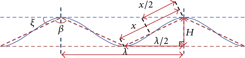
Schematic diagram of wave characteristics [25].
The steepness of a wave is very important for the power output as well as the survival of the device. For a floating WEC with length greater than or equal to x, some parts of the device can get submerged more than what is required when the waves get steep. Even if there is no structural damage, the power output can be affected. A smaller device, on the other hand, will be able to operate in almost all conditions.
A structure in waves faces three types of loads: drag, inertia, and diffraction. Drag loads are due to flow separation, inertial loads are due to the pressure gradients associated with the relative acceleration of the ambient fluid, and diffraction forces are due to scattering of the incident waves due to wave-structure interaction [69]. The calculation of wave forces on a floating WEC can be done by considering the size of the device and the length and height of the incident waves. For small structures, where the diameter of the device is less than 20% of the wavelength, Morison's equation is used to estimate wave forces on the device. The diameter of the device is considered to be small enough compared to the wavelength, so that no significant modifications are done to the incident waves. Morison's equation assumes that wave forces are expressed as the sum of a drag force due to wave fluid velocity and an inertia force due to wave acceleration. For larger structures, diameter greater than 20% of wavelength, the drag forces become negligible since flow separation will not occur; thus, Morison equation is no longer applicable. Diffraction theories are used to account for diffraction, reflection, and radiation from large structures [5, 37]. The excitation force received from waves by the point absorber depends on its geometry [70].
3.4. Stability
Stability measures the capacity of a floating device to resist overturning moments and withstand the environmental forces of wind, current, and waves. The center of the volume of the fluid displaced by a floating device is known as the center of buoyancy B, and the center of gravity, G, of a structure is the point through which, for static considerations, the whole weight of the structure is assumed to act. While designing, it is extremely important that all the weights on the device are accounted for while calculating the centre of gravity [66]. The condition for stable equilibrium of a floating device requires a restoring couple to return the device to its original position following angular perturbation. A floating structure will be in a state of equilibrium when the resultant of all the forces acting on it is zero and the resulting moments of these forces are also zero [5, 9, 10, 71, 72].
Consider a symmetric device floating at rest as shown in Figure 14. The center of gravity, G, is positioned on a vertical line through the center of buoyancy, B, because of rotational equilibrium. If the device faces an external heeling moment M H , it will incline with an angle ϕ. The floating device heels about the centre of floatation, which is an imaginary pivot point located at the point of intersection of the two water planes created by the immersed and emerged volumes. As a result of heeling, the shape of the underwater part of the device will change and the center of buoyancy shifts from B to B″ on a line parallel to the line through the centers of the emerged and immersed wedges z e z i [5, 9, 10, 72]. For equilibrium to be achieved, the righting stability moment M R should equal M H :

where ρ is seawater density, g is gravity, and ∇ is displaced volume. The righting stability lever arm, GZ, can be calculated as

where M is the metacenter and ϕ is the angle of inclination. The stability lever arm GZ is determined by the hydrostatic properties of the submerged portion and the position of the center of gravity [9, 10]. The metacenter, M, which is the point of intersection of the lines through the vertical buoyant forces at a zero angle and at an angle of ϕ, is defined by the angle of inclination and the shape of the emerged and immersed wedges. For a stable equilibrium, the metacenter positions must both lie above the centre of gravity, although the centre of buoyancy need not do so [73].
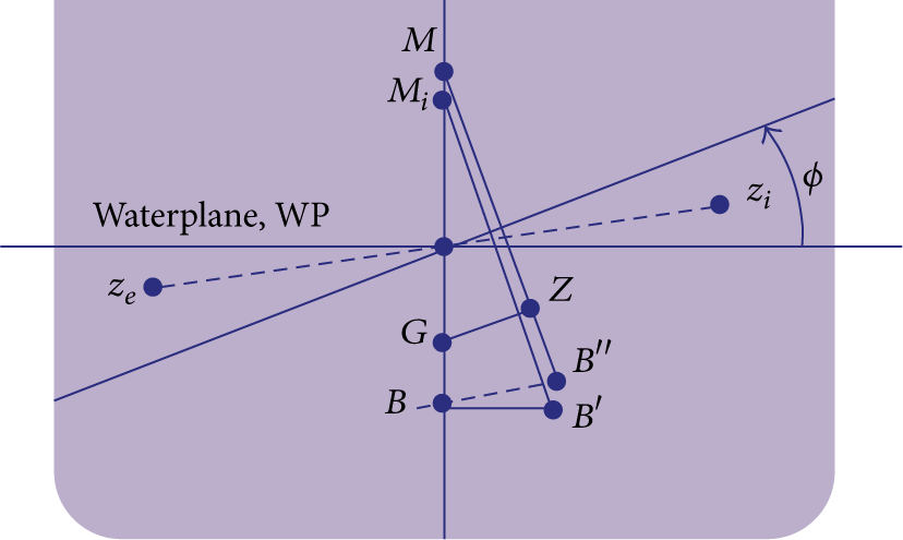
The shift of z e of the emerged wedge to z i of the immersed wedge can be split into a horizontal and a vertical shift. The horizontal shift causes a horizontal displacement of the center of buoyancy from B to B′ calculated as

The horizontal shift describes the initial metacenter, M i , as shown in the figure. The distance BM i can be calculated in terms of the moment of inertia of the water plane, I, and the displacement volume ∇:

The vertical shift causes a vertical displacement of the center of buoyancy from B′ to B″ which is calculated as

The vertical shift describes the metacenter, M, as shown in the figure. The distance M i M can be calculated in terms of the moment of inertia of the water plane, I, the displacement volume ∇ and the angle of heel ϕ:

The distance BM can be calculated from superposition of (6) and (8):

At small angles of inclination, the effect of the vertical shift of the center of buoyancy can be ignored but must be accounted for at large angles of inclination [9, 10]. An important parameter in understanding the floating device stability is the GZ-curve or stability curve. Figure 15 shows a schematic of a static stability curve for a symmetric device, for positive GM. The condition for positive stability for a floating body is to have the metacenter above the centre of gravity (positive GM) [73]. The GZ, which strongly depends on the angle of inclination, is a measure of how stable or unstable a floating device is at varying angles of inclination. The range of angles for which GZ is positive is known as the range of stability [74].

For the floating device to be stable, the GZ should be positive for all angles. The area under the curve gives the righting energy, and the larger this area, the greater the capacity of the floating device to right itself [75]. The maximum value of GZ, which will occur at a particular angle of inclination, will give the largest steady heeling moment that a floating device can resist without capsizing. For a particular angle, known as the angle of vanishing stability, GZ will reduce to zero. For very large angles, the value of GZ can become negative, giving negative stability which can capsize the device [10, 74]. The shape of the stability curve depends on the geometry and the load of the floating device. The mass distribution of the floating device can change with angle of inclination and the associated shift of the centre of gravity results in a reduction of the righting arm GZ. This leads to losses in stability. The mass distribution can change due to effects of liquids with free surfaces in the device, due to freely suspended loads, and due to loads applied from the mooring system [5, 72].
If the water intersecting sides of a device are vertical for some distance above and below the water plane, then the device can be stated as a wall-sided structure. The wall sided criteria is however no longer valid when the angles become so large that the water plane changes rapidly, for example, when the corner of the sides of the device that meets the bottom of the device comes out of the water [5, 10]. For very large angles of inclination and for complex geometries, pressure surface integrals executed through computer programs can be used to define the stability of the floating device [5].
3.5. Natural Frequency
The structure of a floating device has its own natural frequency which is determined from the mass and the elastic characteristics of the structure and its mooring system [8]. The motions of a point absorber are cyclic and their response depends on the frequency of the exciting waves. At wave frequencies corresponding to the natural frequency of the device, motions are more pronounced, and if suitably harvested, maximum power can be generated [11].
Vibration is undesirable in most physical systems, except for a system where energy from vibration is extracted for useful purposes [8]. In free oscillation, no external forces act on a device. The structure will return to its equilibrium place if displaced from its original position. Forced oscillation is when an external oscillatory force acts on the device, forcing it to vibrate with the forcing function. Forced vibration, unlike free vibration, continues as long as the excitation force is present. A device undergoes periodic oscillation about its equilibrium position when the excitation force repeats itself at a particular time interval [8].
The natural frequency of a point absorber is determined from the mass and elastic characteristics of the structure and the mooring system. If the damping is small, then it will take a long time for the device to come to rest at its equilibrium position after being displaced. For large damping, the device may not oscillate at all before coming back to rest, since no appreciable vibration is expected to occur, even when the device is excited externally at its natural frequency. Damping is the dissipation of energy by resistance. The response of a device will be very high without damping [8]. Without damping, a device will keep moving continuously once excited. This is however, impractical, since every motion extinguishes with time. The rate of decay of the motion of a device can be studied when damping is included [76].
An analysis of the free and forced oscillations can provide complete information on the behaviour of a floating device. However, for practical reasons, the only experimental method that is accurate enough to predict the behaviour is to determine the device frequency characteristics, consisting of the amplitude characteristics and phase characteristics. These quantities are determined by measuring the amplitude of motion of the device as a response to a harmonic excitation force. The excitation force and resulting motion are both sinusoidal (for a linear system) as shown by Figure 16 [76].

Schematic diagram showing harmonic excitation and the resulting motion (X a is amplitude of excitation force, x a is amplitude of motion, ε is phase, and ω is excitation frequency) [76].
The differential equation of motion that represents vibration for a device for a single degree of freedom can be obtained from the inertia, restoring force, damping force arising from fluid viscosity effects, and the harmonic excitation force [5, 73, 76].
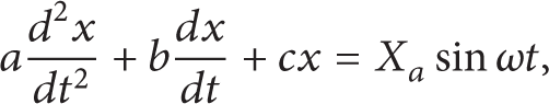
where a is the virtual mass (m + m w ), m is the mass of the device, m w is the added mass, b is the damping coefficient, and c is the spring coefficient. The added mass is shape dependent and is a result of the disturbance of the flow field [6]. For a system with multidegrees of freedom, the equation of motion is given as
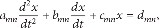
where a mn is the total mass in m direction due to a motion in n direction, b mn is the damping in m direction due to a motion in n direction, c mn is the spring coefficient in m direction due to a motion in n direction, and d mn is a linear reaction force in m direction due to a motion in n direction. For a single degree of freedom, the behaviour of a system is independent of the behaviour of the other degrees of freedom. However, for multidegree freedom system, the behaviour of each degree of freedom affects the other. Laplace transforms are used to solve this complex phenomenon [76].
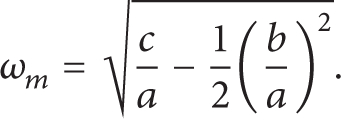
Unlike an undamped system, a damped system will oscillate with limited amplitude even at resonance. However, the maximum amplitude of device oscillation at a particular amplitude of the excitation force may not necessarily occur at resonance [10, 76]. There are three special frequencies used for practical reasons:
the undamped natural frequency which is independent of amplitude of motion [76]:

the damped natural frequency (also independent of amplitude motion):

the frequency at which the response of the motion to a harmonically oscillating excitation force becomes maximal:
Spring forces are introduced due to the buoyant forces due to the structures underwater form, mooring forces due to the weight of the mooring lines, and elastic forces in the device or mooring lines. The spring force for a submerged device occurs in the pitch and roll motions only. However, for a floating device, a heave motion will also introduce spring forces [76].
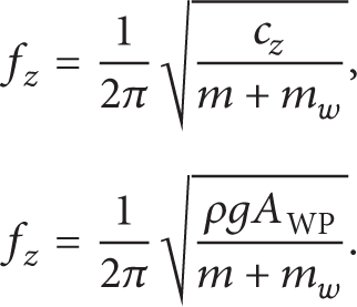
The restoring spring coefficient for a floating system in heave is given as [73, 76]

where ρ is seawater density, g is gravity, and AWP is the area of the water plane.
The natural frequency of a floating body in heave motion is thus calculated as [2, 73]
The restoring spring coefficient for a floating pitching system is given as [73, 77]

The natural frequency of a floating body in pitching motion is calculated as [2, 73]

where I y is the mass moment of inertia of the device, and I w is the added mass moment of inertia.
The natural frequency can be tuned by varying the mass and the spring constant [59]. Increasing mass can lead to bigger and heavier devices with higher structural costs [11]. Resonance is achieved by tuning the natural frequency of the device to coincide with the incident wave frequency [59]. The resonance frequency bandwidth of a point absorber does not usually coincide with the spectrum of the incident ocean waves, and the band is mostly narrow. Also, the incident wave heights have a lot of variations from one wave to another. Thus, it becomes important for a point absorber to be equipped with phase control of the oscillation as well as amplitude control [67].
The optimum phase condition accounts for the frequencies that are away from the resonance frequency of the point absorber but still in the resonance bandwidth. Large WECs have larger bandwidths and it becomes narrower with device size reduction [64]. To optimize power output from a point absorber, the device velocity must be in phase with the excitation force. The phase condition is satisfied by matching the incident wave frequency to the device natural frequency. In practice, it is difficult to achieve optimal response but methods such as latching can be used to minimize the phase difference between the velocity and the excitation force [78].
Latching control locks the motion of the device at the moment when its velocity is zero at the end of one oscillation and then releases it at the next favorable condition. The latching delay for regular waves, when the wave period is longer than the natural period of the device, can be set to half the difference between the wave period and the natural period of the device [51]. The unlatching should be done at least one quarter natural period before the next maximum wave force [64]. Energy absorption and conversion can also be improved if a wave prediction strategy is utilized [59]. Wave prediction strategies predict the incident wave a few seconds in advance to calculate the optimal motion for maximum wave energy extraction [59, 67].
3.6. Mooring
Mooring systems are designed to keep the device at the desired station within specified tolerance under varying operating conditions [79]. Mooring is a major part of the wave energy conversion system. The associated costs for a mooring system can exceed the other subsystem costs and can thus become the determining factor in the cost effectiveness of the total system [2]. The technology for offshore oil and gas mooring can be used as a basis to design mooring systems for floating WEC's, but cannot be directly applied since the design approach for floating WEC depends on some factors that are totally different for offshore conventional oil and gas structures [41]. The mooring system should be designed to withstand the various environmental loading to have minimum forces on the WEC [2, 53]. Ideally, the particles of water waves undergo orbital motion. Thus, a freely floating point absorber will ideally follow the orbital motion of water particles. This motion will affect the mooring system. The mooring system can influence the wave energy extraction of a point absorber by interacting with its oscillations [13, 14].
The installation depth for point absorbers is much shallower than offshore oil and gas installations [41]. Together with installation location, the types of technology used for wave energy extraction and the degrees of freedom of the point absorber also have to be considered when designing mooring systems [46]. The mooring of a floating point absorber can influence the wave energy extraction by interacting with its oscillations [80]. Thus, the mooring system has to be designed in a way that it does not hinder the device oscillations and power output [41].
Mooring systems will face loads from waves, wind, tidal changes, ocean currents, and the large oscillatory forces [80, 81]. All these forces can affect the overall motion of the point absorber and the stiffness, tension, and damping properties of the mooring line. These loads become critical when the device and the mooring are considered as a coupled system [46]. However, if the motion of the device can be isolated from the mooring system, the efficiency of the device is maximized [2]. The floating device and the mooring system can be analysed separately, where the mooring system is considered as an external nonlinear stiffness term. Coupled analysis of the floating device and mooring system is considered when the size and weight of all the components are comparable and when the influence of one on the other increases [8].
The pretension, the choice of materials for the mooring line, and mooring geometry can be used to determine the stiffness characteristics of a mooring system [41]. The stiffness characteristics alter the damping, natural frequency, and the motion of the mooring and device system [5, 41]. A stiff mooring system can be used to restrict the motion of the WEC, but it may be very expensive from a design perspective [41]. The first step in designing a mooring system for a particular application is the determination of the mooring configuration [2]. Harris et al. [79] presented the main types of mooring conFigurations suitable for floating WECs. They ranked the configurations as high, medium, and low to describe the mooring configurations in relation to safe station keeping and moderate installation costs. They identified some configurations as medium since the installation costs are expensive but have the potential to improve energy extraction. The possible mooring configurations that were presented are single point mooring, spread mooring, and dynamic positioning configurations. Table 1 describes the types of mooring configurations under these categories. In single point mooring, the floating device is moored to a mooring point in the ocean, where the floating device can weathervane to align itself to the response of waves, winds, and currents. In spread mooring, the device is moored using a set of mooring lines and is not allowed to revolve in any direction. In this case, the wave forces on the WEC will be very high [79, 82, 83]. Spread moorings are suitable for a system that is not very sensitive to the direction of incident waves [84]. Dynamic positioning is a computer controlled system that automatically maintains the floating device at the desired position through the use of thrusters or propulsion either on the device or the mooring line [85, 86]. Thus, for a point absorber that requires aligning itself to the incoming waves (mostly for pitching systems such as the Searev), the mooring system has to allow for weathervaning. The requirement for a point absorber WEC to weathervane depends on the type of energy extraction method.

The choice of the mooring configuration depends on the location, operating principles of the floating WEC, and environmental conditions. As a suggestion from McCormick [2], the most suitable mooring configurations for deep water floating WEC mooring are slack mooring and tension mooring. For shallow water, slack mooring is suggested since tension mooring may be affected by the large tidal currents. Primary mooring components are the mooring lines, anchor, connecting elements, and floats. These components are decided by the mooring configuration, the location, the life time of the mooring system, seabed conditions, and design specifications of the WEC and associated costs [79].
There are three categories of materials that are mostly used for mooring: (1) metals (wire or chain) (2) synthetic materials (nylon line, etc.), (3) natural nonmetallics (manila rope, etc.) [2, 79]. According to McCormick [2], for energy conversion systems, (1) and (2) are practically considered for use [2]. Barltrop [84] presented an analysis of chain, wire rope, and fibre ropes and suggested that a combination of chain and wire rope for floating systems provides optimum performance at a wide range of water depths. The key parameters in selecting material for mooring purposes are breaking strength, elastic modulus, and submerged weight per unit length. The elastic modulus and the submerged weight often dictate the breaking strength required of a particular mooring configuration. Figure 17 shows a comparative review of the breaking strength, elastic modulus, and submerged weight per unit length normalized by the square of the line diameter of the mooring line [84]. It can be seen that chain is the heaviest, has highest breaking strength, and has the highest elasticity. The fibre rope is almost neutrally buoyant (light weight), making it a good option for effective station keeping in deep water. The choice of a suitable anchor depends on the water depth, the sea bed material and slope, and the cost [2, 79].

A comparison of chain, wire rope, and fibre rope properties [84].
The mooring system should be capable of lasting for at least 30 years, with component replacement after 5 years or more [79]. If there is an array of floating point absorbers, then the mooring systems of the devices should not make any contact [41], even when maintenance is being carried out on one mooring system [46]. A mooring design and analysis for offshore floating structures with rules for classing and building of single point moorings are provided in [87]. The selection of the mooring system has to consider some cost-effective factors such as environmental conditions, water depth, installation complexity, operation and maintenance, capital and operating costs, downtime, and emergency repairs [86].
3.7. Scaled Modelling
Model testing provides valuable information which predicts how a prototype would behave under similar conditions [88]. Some of the principle benefits gained from model tests are validation of design values, obtain design empirical coefficients that can be directly applied to the prototype, verify the analytical techniques, verify offshore operation, and investigate unpredicted and unexpected phenomena [8].
Similitude is achieved between the model and the prototype when all major factors having an influence on the model and prototype have been identified and dimensionalised. The model and prototype should be geometrically, kinematically, and dynamically similar ensuring that the model correctly represents the prototype [6, 85]. Since testing is mostly done at small scales, hydrodynamic scaling laws are applied to measure up the test data to full scale. These scaling laws are derived from the ratio of forces commonly encountered in a hydrodynamic model test [8]. However, it is difficult to find simultaneous equalities for all the scaling laws [85].
A typical wave-structure interaction problem scaling involves the Froude number, Reynolds number, and Keulegan-Carpenter number. For structures that are subject to deformation or defined as an elastic structure, Cauchy number should be considered as well. The Strouhal number is considered for a structure vibrating in a fluid medium [8, 88]. Table 2 summarizes these laws, where ρ is density, v is velocity, L is characteristic length, μ is coefficient of dynamic viscosity, g is gravitational acceleration, T is period, and f is vortex shedding frequency.

Froude number is the most appropriate scaling law for fluid-structure model tests. In some cases, the Reynolds number also becomes important. However, simultaneous satisfaction of Froude number and Reynolds number is very difficult. The distortion in the Reynolds number is large when Froude scaling is used. The distortion can be so large that the model flow can be laminar while the prototype flow is turbulent [8]. The Reynolds number difference therefore has to be accounted for by other means, such as maximizing the scale of the model to simulate the prototype as closely as possible, and by tripping the laminar flow in the model by introducing roughness on the front part of the model. Tripping the laminar flow allows the model to see turbulent flow in most parts. This method however works best for long models. A mesh barrier can also be submerged below the water surface ahead of the model to trip the flow [88].
Power representation in Froude scaling is very difficult due to the large power scaling factor between model and prototype. Offshore WEC model tests are mostly done at scales of 1: 80–1: 25 in small to medium sized wave tanks and up to 1: 10 scale in the largest and deepest wave tanks. Theses scales are extremely small for a PTO system to be realistically modelled and developed [86]. For example, for a scale of 1: 10 and for a prototype PTO system of 100 kW, the model would have a power output of 0.03 kW, which is too small for a realistic simulation. The PTO can however be tested separately in a laboratory at a large model scale or a full scale by means of hydraulic or electrical actuators that directly drives the moving part of the PTO [86]. A list of scale factors for Froude scaling is given in [83].
The Strouhal and the Keulegan-Carpenter similitude, which provides the similitude for unsteady fluid, are both satisfied simultaneously when Froude scaling is used. In small scale testing, the Froude model assures the similitude regarding the Keulegan-Carpenter number [8]. The Cauchy number becomes important when the inertial forces are large enough to change fluid compressibility [89]. The fluid (seawater) can be considered incompressible and thus can be ignored for point absorber testing. Elastic properties of mooring lines are modeled using the Cauchy number [85, 89].
The wave tank used for model testing should give reliable results that can be confidently used to predict prototype behaviour. A wave tank should have proper instrumentation techniques, relevant softwares to record and analyse waves, and should be capable of generating waves as well as simulating wind and current effects. The wave tank should also have a wave absorption system towards the end side of the tank to minimize wave reflections. The wind effects can be simulated by using a blower located just above the water surface close to the model. The wave tank used should give reliable data by minimizing scale effects and all types of measurement errors [88].
Scaled models of mooring systems can be studied experimentally in wave tanks [90]. Some properties of mooring lines that should be modelled as accurately as possible are vertical and horizontal pretension components, vertical and horizontal stiffness, line mass, and drag characteristics [88]. The weight of the chain per unit length is an important property of the mooring line. The material and size of the model chain should be such that the weight of the chain can be modelled at a small scale. The geometry of the chain is difficult to scale, making it very difficult to study the vortex-induced vibrations at small scales. This introduces inaccuracy in simulating the hydrodynamic damping of the chain generated from its own motion as well as from current and wave forces. Hydrodynamic damping of the mooring line could have a significant effect on the response of the point absorber at its natural frequency [8, 88].
The model testing of the point absorber (and for any other wave energy converter) has to be carefully designed, with all the important parameters considered. Figure 18 shows a summary of steps in executing a model test [83]. Guidance for experimental testing for wave energy converters is given in [91].
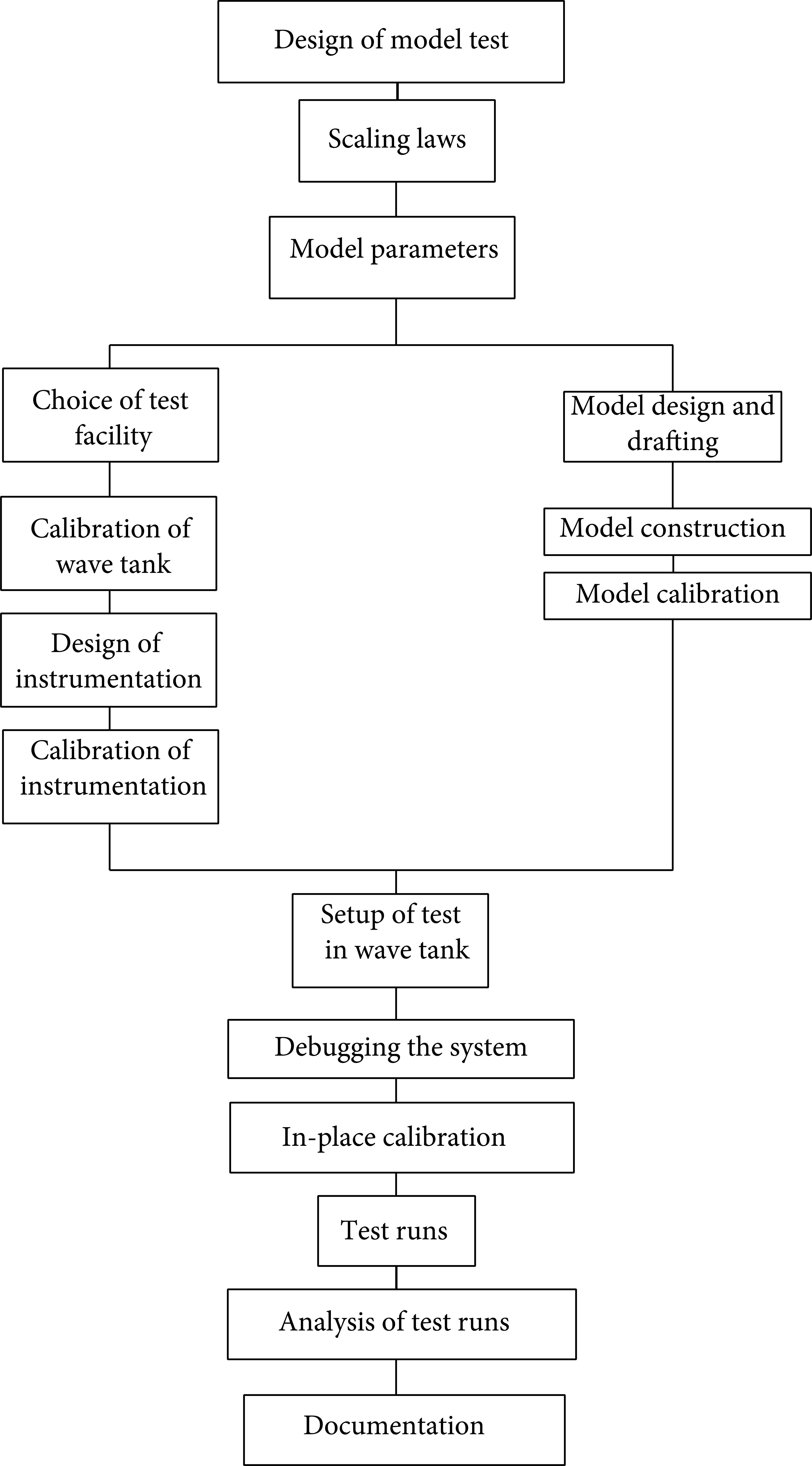
Steps in executing a model test [83].
3.8. Pilot and Full Scale Devices
A pilot device is a smaller version of the final device, built to obtain knowledge of the performance at similar operating conditions. Pilot device testing confirms the results obtained during scaled modelling. Pilot testing demonstrates the operational viability, and the design of the final device can change a lot to get the optimum output at various operating conditions.
As mentioned in Section 2.1, the wave resource at a given location has to be observed for at least one year. Thus, the pilot device should also be tested for at least one year, and for varying seasons as well since the available wave energy may have seasonal variations at a given location. Proper instrumentation should be used to collect and transmit data of a pilot device. The analysis of this data will serve as a guideline as to which component (e.g., mooring system or motion response of device) needs more attention to optimise the performance of the final system. The results from pilot tests and the associated design changes will reduce huge costly problems and ensures survivability of the final device.
PowerBuoy device has been tested in Scotland, Spain, and Hawaii. It is developed by Ocean Power Technologies, a company with offices in the UK, Australia, and the United States. Pelamis developed by the Scottish Company Pelamis Wave Power has been deployed in some locations in the UK and Portugal. Pelamis was the world's first WEC to be grid-connected in 2004 [92].
4. Conclusions
An overview of the most important parameters involved in developing floating point absorber WECs is presented. The wave energy resource has regional and seasonal variations, with higher energy mostly available in deeper water. The wave energy resource available at a particular location has to be assessed for all the seasons. This data can then be represented in an energy spectrum which gives the energy distribution of the waves at that location. The wave characteristics can be used as a basis to finalize the dimensions or geometry of the WEC. The wave height, period, and water depth data are mostly obtained from wave gauges. This can be used to calculate the wavelength using an appropriate wave theory, keeping in mind the limitations of the wave theories. The wave theories used to calculate the wave characteristics are different at different water depths. The PTO systems are different for different WECs, mainly categorised as direct drive system and buffer systems. In direct drive systems, the moving part of the generator is directly coupled to the moving part of the WEC. In a buffered system, the wave energy is first captured by a primary medium, after which it gets transferred to the generator. Due to the irregular nature of the waves, the power output will have a lot of variations and thus is a challenge to condition it to suit the requirements of the main electricity grids.
The wave-structure interaction leads to modifications in the path of wave travel. Effects such as wave radiation from a device affect the incident waves and thus the energy capture and the power output. The different types of device motions (heaving and pitching considered here) modify the incident waves in different waves and the power capture varies as well. A point absorber, being much smaller than the wavelengths, has advantages of high energy capture as well as less chances of being damaged in the hostile environment of the ocean. The stability of the point absorber is important as it will prevent the device from capsizing. The stability lever arm is an important parameter in deciding the stability of a device. The stability of a point absorber can be represented in a stability curve, which shows the variations in the stability lever arm at different inclination angles. The device should be designed to stay in the range of stability (angles for which the stability lever arm is positive).
Optimum power output of a point absorber can be obtained when the incident wave frequencies are close to or correspond to the natural frequency of the device. The natural frequencies are calculated by considering the total mass of the system as well as the stiffness characteristics and can therefore be tuned by varying the mass or the stiffness. The natural frequencies are different for heave and pitch systems. A mooring system maintains the point absorber at the desired location. The choice of the mooring configuration depends on the energy extraction method of the point absorber. Single point mooring configuration allows the device to align itself to waves arriving at the device at different angles, whereas spread mooring does not. The common materials for mooring systems are chain, wire rope, and fibre rope. The elasticity in a mooring line has to be considered to allow for the correct prediction of the line tension.
Scaled modelling provides important information as to how the final device would behave under similar operating conditions. For a scaled model to correctly represent the prototype, all major factors should have similitude. However, similitude is not always achieved, such as similitude for Reynolds number and Froude number. The Froude scaling criteria are the most appropriate for fluid-structure model tests. A list of scale factors for Froude scaling is presented. Power representation in Froude scaling is difficult due to the large power scaling factor between model and prototype. However, the power take-off mechanisms can be separately tested at larger scales. The execution of the model tests has to be systematic, with all the major parameters carefully planned and executed. A pilot device is a smaller version of the final device. Pilot testing confirms the results obtained during scaled modelling. The results of pilot testing can help to optimise the performance of the final device. Pilot testing has to be done for a considerable time (preferably one year), in which it will be able to operate in different wave environments due to different seasons.
Conflict of Interests
The authors declare that there is no conflict of interests regarding the publication of this paper.
Footnotes
Acknowledgment
This research was supported by Korea Ministry of Knowledge and Economy and KETEP (Project no. 2011T100100688).