
Abstract
This work presents a novel 4-degree-of-freedom (4-DOF) haptic master using magnetorheological (MR) fluid which is applicable to a robot-assisted minimally invasive surgery (RMIS) system. By using MR fluid, the proposed haptic device can easily generate bidirectional repulsive torque along the directions of the required motions. The proposed master consists of two actuators: an MR bidirectional clutch associated with a planetary gear system and an MR clutch with a bevel gear system. After demonstrating the configuration, the torque models of MR actuators are mathematically derived based on the field-dependent Bingham model. An optimal design that accounts for spatial-limitation and the desired torque constraint is then undertaken. An optimization procedure based on finite element analysis is proposed to determine optimal geometric dimensions. Based on the design procedure, MR haptic master with the optimal parameters has been manufactured. In order to demonstrate the practical feasibility of the proposed haptic master, the field-dependent generating repulsive force is measured. In addition, a proportional-integral-derivative (PID) controller is empirically implemented to accomplish the desired torque trajectories. It has been shown that the proposed haptic master can track the desired torque trajectory without a significant error.
1. Introduction
Recently, robot-assisted minimally invasive surgery (RMIS) has attracted more and more interest from numerous researchers in the field of mechanical engineering and medical science. The ZEUS@ surgical robotic system and da Vinci surgery system are the most successful commercial applications [1, 2]. A RMIS system usually consists of a master device which tells a surgery robot how to operate surgery using long surgical instruments and a surgery robot which operates under the guidance from the master device signal. The interaction information between a surgeon and a patient is only visual images taken by an endoscope attached to the tip of the laparoscopic device [3]. This information is vital, but it is very difficult to comprehend the overall scheme inside the abdomen of a patient. Accordingly, there is a chance of inaccurate operation due to the lack of physical sensing. Therefore, it is indispensable to develop a haptic master whose function is not only to generate the motion for a robot but also to reflect to the surgeon the physical constraints of the robot, such as those from the viscosity and stiffness of the touched tissue, bone, and organs.
The realization of human senses, especially touch, has been actively researched in several applications such as the automotive and robotic fields in order to accomplish greater realism and interactivity [4, 5]. A haptic system provides stimulus information such as tactile sensation or kinesthetic force to a user. The first haptic system was developed by Goertz during the 1940s for a master-slave manipulator for handling dangerous materials. Since then, various medical haptic devices featuring an electric motor, wire, and links have been studied. However, using these haptic devices it is difficult to obtain a continuous and smooth torque control. Particularly, since the active type directly transmits force to the operator, it can cause safety problems [6, 7]. Due to this problem, haptic devices must be further developed, because the human sense of touch is far more sensitive than the sense of sight or hearing. Therefore, several researches related to haptic systems have recently been implemented using smart materials such as magnetorheological (MR) fluids and electrorheological (ER) fluids. MR fluid is actively being investigated as an actuating fluid for numerous applications [8–10]. MR clutch and brake mechanisms featuring smoothly controllable torque have been broadly researched for high stability and performance [11, 12]. It is widely known that MR fluids undergo instantaneous phase changes when they are exposed to a magnetic field. The most important change is related to the yield stress. Due to this phenomenological behavior, the MR applications have several advantages, such as good stability, reliable control performance, and compact design. These features are ideal for haptic systems. Accordingly, the advantages of MR have led to several research works for haptic devices. Li et al. [13] proposed an MR fluid-based 2-degree-of-freedom (2-DOF) haptic system featuring a gimbal structure. Senkal and Gurocak [14] developed a 3-DOF MR spherical brake, and its performance was evaluated by virtual tests. Nguyen and Choi [15] proposed a 2-DOF MR haptic device featuring a bidirectional clutch mechanism and gimbal structure. In order to apply a haptic master for RMIS applications, 4-DOF motion is required, which includes 3-DOF rotational motion (about the X, Y, and Z axes) and 1-DOF translational motion [16]. However, the research on 4-DOF MR haptic devices for medical applications using MR fluid has not been proposed so far.
Consequently, the main contribution of this work is to propose a novel 4-DOF haptic master using magnetorheological (MR) fluid which can be applicable to RMIS systems. The proposed kinesthetic force-feedback master consists of two actuators: an MR bidirectional clutch with a planetary gear system and an MR clutch with a bevel gear system. After deriving the torque models, the geometric dimensions of the MR haptic master are optimally obtained to meet the spatial-limitation and torque requirements. It is demonstrated via experimental investigation that the predicted performance is successfully achieved by implementing the proposed 4-DOF haptic master. Finally, a PID controller is experimentally implemented to achieve the desired torque trajectories of the haptic device. It is shown that the tracking control performance is good without a significant error between actual and desired torques.
2. Mechanism of 4-DOF MR Haptic Master
Since RMIS is conducted using small incisions to the abdomen, the motion of an instrument is restricted to four directions (pitching, rolling, yawing, and translation motion), as shown in Figure 1. As mentioned, it is highly necessary to realize repulsive force for surgeons in RMIS. So, an MR haptic master mechanism is proposed to achieve the required motions and repulsive force-feedback, as shown in Figure 2. In addition, to send the complex motions of the operator to the repulsive force actuators, a gimbal mechanism is adopted. The proposed MR haptic master consists of two actuators. One is a bidirectional MR clutch with a planetary gear system, which can generate rolling and pitching rotational force reflections. The other is an MR clutch attached to the gripper of the gimbal mechanism for yawing and translation motion. The reflection of the motion of operator is sent from these MR actuators via the gimbal mechanism. The force reflection mechanism of the MR actuator is realized by an MR fluid. The shear stress produced when a magnetic field is applied to the MR fluid can be expressed as follows [17]:

where τ is the total shear stress of the MR fluid, η is the viscosity constant,

In (2), B denotes the magnetic flux density in units of Tesla, and H denotes the magnetic intensity in units of amperes/mm.

Required motions of MR haptic master for RMIS.
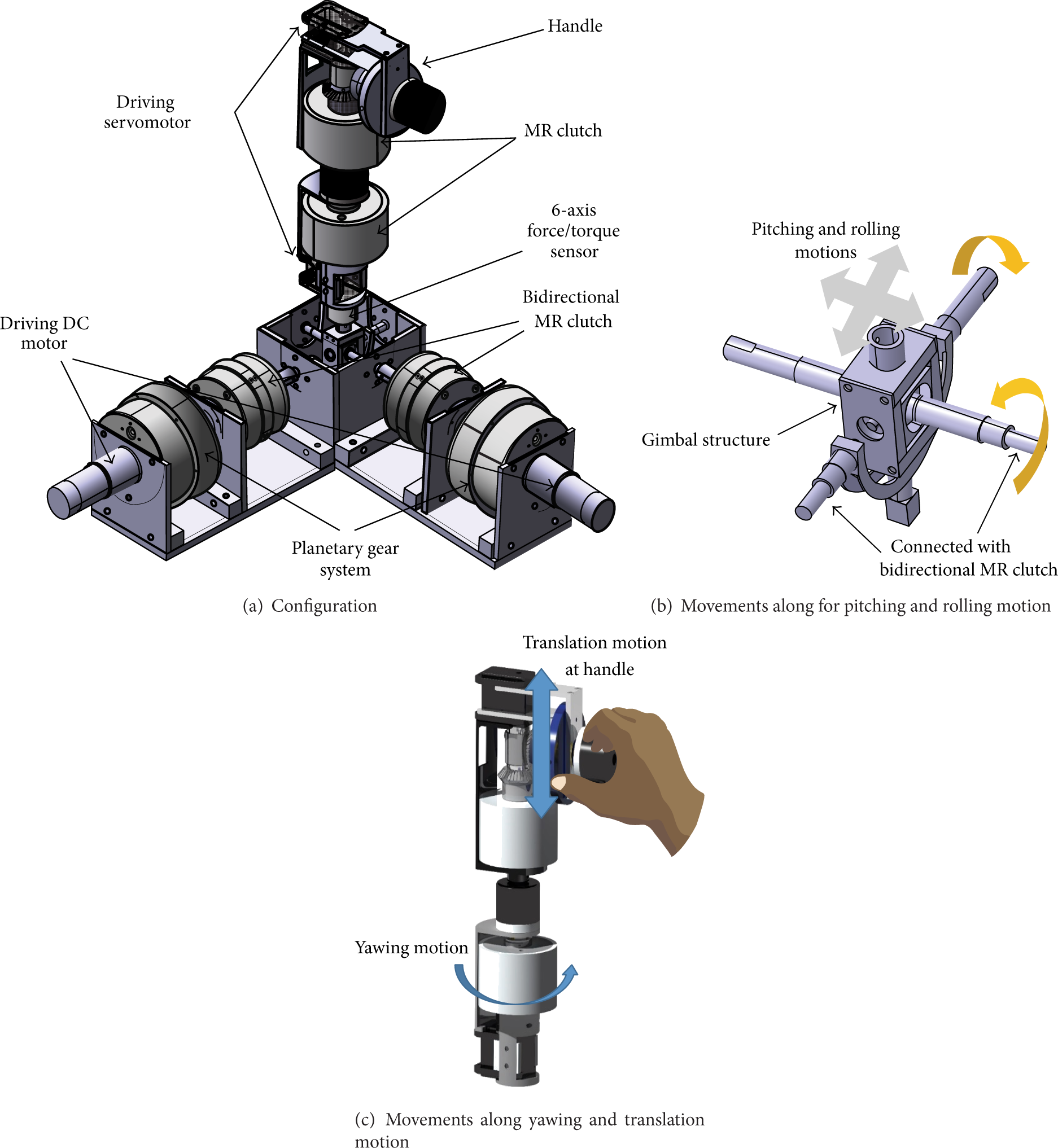
Schematic configuration of MR haptic master.
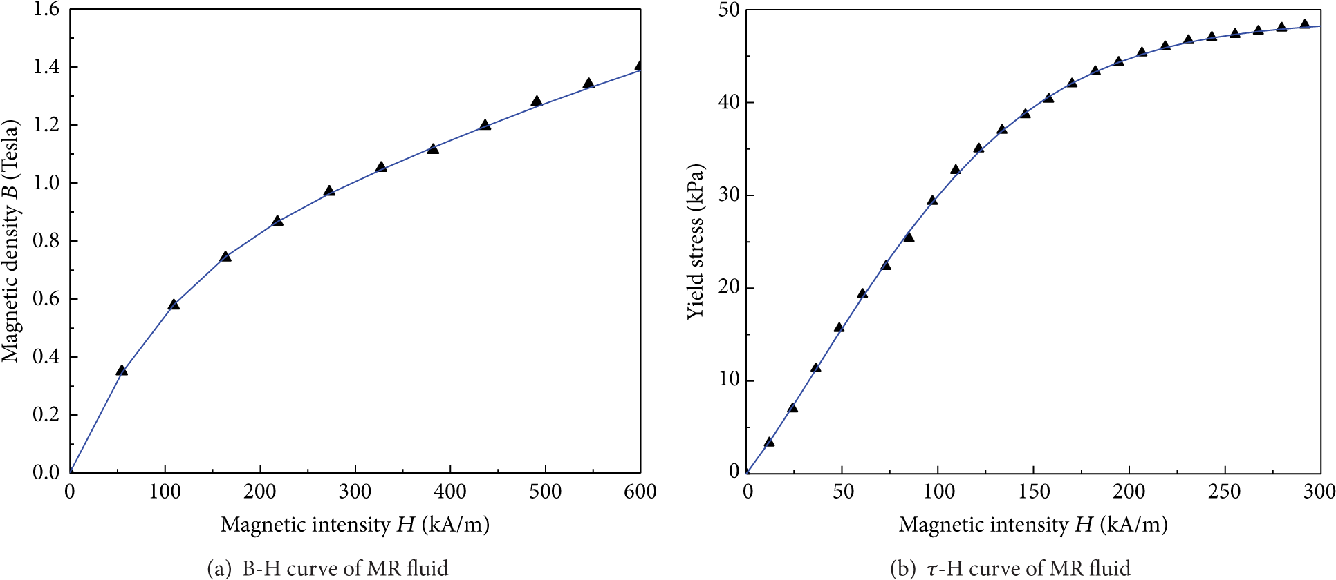
Rheological properties of MR fluid.
2.1. Bidirectional MR Clutch with Planetary Gear System
In order to realize the 2-DOF force reflection along the pitching and rolling directions, a bidirectional MR clutch and a planetary gear system incorporated into a gimbal mechanism are proposed. Figure 4 illustrates the configuration and geometric features of the proposed bidirectional MR clutch. The bidirectional MR clutch is composed of two coils, two rotors, and an outer casing. The two rotors are fixed to their respective shafts, which transmit motion from a planetary gear system as a driving bioutput source. As shown in Figure 5, the driving motion of the motor is split into two different rotational motions of shafts 1 and 2. When the motor runs, the two shafts and two rotors rotate counter to each other. Due to these configurations, there are two relative shear motions between the two rotors and the outer casing, even when the casing is stopped. The casing is fixed to a driving shaft, which is connected to the gripper of the MR haptic master. The MR fluid fully fills the space between the rotors and casing.

Bidirectional MR clutch.

Planetary gear system for motion transmission to the bidirectional MR clutch.
In order to generate bidirectional force reflection, two distinct current amplifiers are used for the coils so that the current magnitudes of these coils can be controlled independently. Since these independent magnetic field inputs cause one magnetic field to interfere with the other, a nonmagnetic partition is inserted at the middle position of the casing. When power is supplied to a coil, due to the solidification of the MR fluid between the surfaces of the rotors and the casing, the outer casing rotates according to the motion of the rotors. In this context, the direction of the torque is determined according to the excitation scheme of coils 1 or 2. Also, since the repulsive force at the gripper originates from the generated torque of the MR clutch via the gimbal structure, the terminology “repulsive torque” will be used instead of “repulsive force” in this work. The torque induced by the MR clutch consists of two elements: the dry friction torque from the sealing scheme and the fluid friction torque from the MR fluid. In order to prevent leakage of MR fluid, the oil seal is tightly connected with shaft of MR actuator. So, dry friction torque is mainly induced by the oil seal. The total generated torque, T bc , can be expressed as follows:
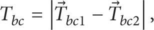
where Tbc1 and Tbc2 are the torques generated from rotors 1 and 2, respectively. These terms can be rewritten as follows:
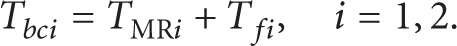
In (4), T fi is the torque due to dry friction between the surfaces of the rotor's shafts and the casing's shaft as well as that from the sealing scheme, which can be determined experimentally. TMRi is the fluid friction torque due to the MR fluid, and its magnitude depends on the properties of the MR fluid and applied magnetic field. This torque is mainly induced by the friction between the rotors and casings and can be expressed as follows:

In (5), T ai is the induced torque between the annular faces of the rotors and the casing, and T ei is the induced torque between the end faces of the rotors and the casing. By substituting (1) into (5), the field-dependent torques is obtained by

In (6),
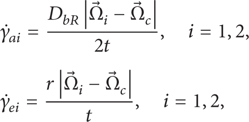
where Ω1, Ω2, and Ω c are the angular velocities of rotors 1 and 2 and the casing, respectively. In this paper, t means gap distance between outer housing and rotor of end and annular faces. Also, in order to simplify the design process, all gap distances for annular and end faces are identically determined to be 1 mm. The yield stresses τ y,ai (B) and τ y,ei (B) do not vary significantly on the shear surfaces [19]. Consequently, for simplicity, (6) can be rewritten in a simpler form as follows:

2.2. MR Clutch with Bevel Gear System Attached at the Gripper
Two actuators for the yawing and translation motions are attached at the gripper of the gimbal structure, which is the main feature of the MR haptic master. If the gripper is long and the generated torques of the actuators for rolling and pitching motions are the same, the transmitted repulsive forces along the pitching and rolling motions are proportionally small. Accordingly, in order to attain a relatively large magnitude of the transmitted force and compact size of the MR haptic master, the length between gimbal structure and handle should be as small as possible. In consideration of these design requirements, a new mechanism for yawing and translation motion is proposed as shown in Figure 6. As shown in Figures 2(c) and 6, bevel gear and handle are devised to transfer rotational motion of MR clutch to translational motion of handle. During RMIS, an operator holds the handle of MR haptic master. In contrast to the mechanism of the bidirectional clutch for the pitching and rolling directions, this mechanism uses a servomotor as a bioutput source. When the power is supplied to the coil, the servomotor generates one directional rotation at a time. Then, the outer housing rotates according to the motion of the servomotor. If power transmission of the servomotor is required in the reverse direction, the servomotor changes its output direction. Then, the outer housing of the MR clutch rotates in the opposite direction. Additionally, an encoder is inserted to measure the command of operator for surgery robot of RMIS system.

Schematic configuration of MR clutch with bevel gear system.
Since the actuator for yawing and translation motion does not require a planetary gear system, the length between gimbal structure and handle is short. However, this mechanism has both strengths and weaknesses. This mechanism can minimize the size of the gripper, but the chance of time delay due to changes in the rotational direction is unavoidable. Since the servomotor can quickly change its rotational direction and the purpose of the MR clutch is haptic application rather than fast power transmission for a mechanical system, the time delay would hardly be noticed by the operator. As shown in Figure 7, the MR clutch is composed of a rotary disc, shaft, outer housing, and MR fluid. The rotary disc has a flux guide and an electromagnetic coil, and it is assembled into an outer housing with a specific gap fully filled with MR fluid. The flux guide is made of ferromagnetic material and is fixed to a shaft made of paramagnetic material, which is in turn fastened to the driving servomotor. In addition, a mild steel (S45C) and an aluminum are adopted as the ferromagnetic and paramagnetic materials, respectively. The outer housing is fastened to an operator. When the current input is supplied to the coil, a magnetic field is created, and fluid friction torque induced by the MR fluid is provided to the operator. In order to derive the torque model of the MR clutch, the same torque analysis of the bidirectional MR clutch is identically applied and obtained as follows:

In (9), T
f
is the dry friction torque of the MR clutch.

Geometric features of MR clutch.
3. Optimal Design and Manufacturing
In this section, finite element (FE) analysis is utilized to obtain optimal geometric dimensions of the MR haptic master in order to maximize the generated torque of the MR haptic master. There are numerous factors that are important in the optimal design process such as the size, the power, and the generated torque. Because the MR haptic master is expected to be applied in low-power applications, the size and the generated torque are considered as more important factors. In the optimal design process, the optimal configurations of the MR bidirectional clutch and MR clutch are determined to maximize the generated torques, while the specific volume defined by its radius and height is constrained.
In order to obtain the optimal solutions of the bidirectional MR clutch, FE analysis is implemented for the magnetic circuit of the master and calculating the generated torque of the master. From Figure 4 and (8), it is known that the generated torque is mainly determined by the diameter of the rotor, D bR ; the height of the coil, h bc ; and radial width of the coil, b c . For the sake of manufacturing, the other parameters such as the gap of the MR fluid, the diameter of the rotor shafts 1 and 2, and the thickness of the partition are preset as 1 mm, 12 mm, 8 mm, and 3 mm, respectively. Also, for obtaining compact size of the bidirectional MR clutch, the constraints in (10)–(12) have to be included. In short, the optimization problem is rewritten as follows:
maximize the generated torque of the bidirectional MR clutch;
subject to


where
In (13),
Predicted torque of bidirectional MR clutch according to varying design parameters.

Figure 8 shows the magnetic density of the bidirectional MR clutch with the obtained optimal dimensions when a current of 2 A is applied to the coil. From Figures 8(b) and 8(c), the magnitude of magnetic density in the gap between the end faces is low and the deviation of magnetic density in the gap between the end faces is relatively low. The magnitude of magnetic density in the gap between the annular faces does not vary significantly on the shear faces. So, a mean magnetic flux density can be used to simplify the design procedures. The mean magnetic flux densities at the annular face and end face of the rotors are 0.393 T and 0.6917 T, respectively. However, an optimization procedure for selecting proper design parameters can be automatically implemented by designing a direction vector [19]. Based on a previous study [19], a log file for solving a magnetic circuit was built, and iteration for finding proper design parameters was executed. By utilizing the direction vector, the convergence of the objective function is accomplished. It is noted that there are no significant differences in geometry between two procedures. Since it is difficult to design the direction vector, the proposed procedure and corresponding optimization procedure are effective and considerably accurate. In detail, suppose that a direction vector is improperly designed. Then, there is chance to find inappropriate solutions. The time consumed for the optimization analysis using the direction vector is shorter than the corresponding analysis in this work. However, there is no significant difference in the calculation time when considering only a few parameters.

Magnetic flux density of the bidirectional MR clutch with optimal dimensions.
The optimal design technique for the MR bidirectional clutch is identically applied to the design of the MR clutch. From Figure 7 and (8), the chosen design parameters are the diameter of the shaft, D cs ; the height of coil, h cc ; and the radial widths of the coil, b cc . The other parameters such as gap of the MR fluid, t; diameter of flux guide, D cR ; and height of the flux guide, h cc + 2h c are preset as 1 mm, 62 mm, and 32 mm, respectively. The optimization problems for the MR clutch can be presented as follows:
maximize the generated torque of the MR clutch;
subject to

where
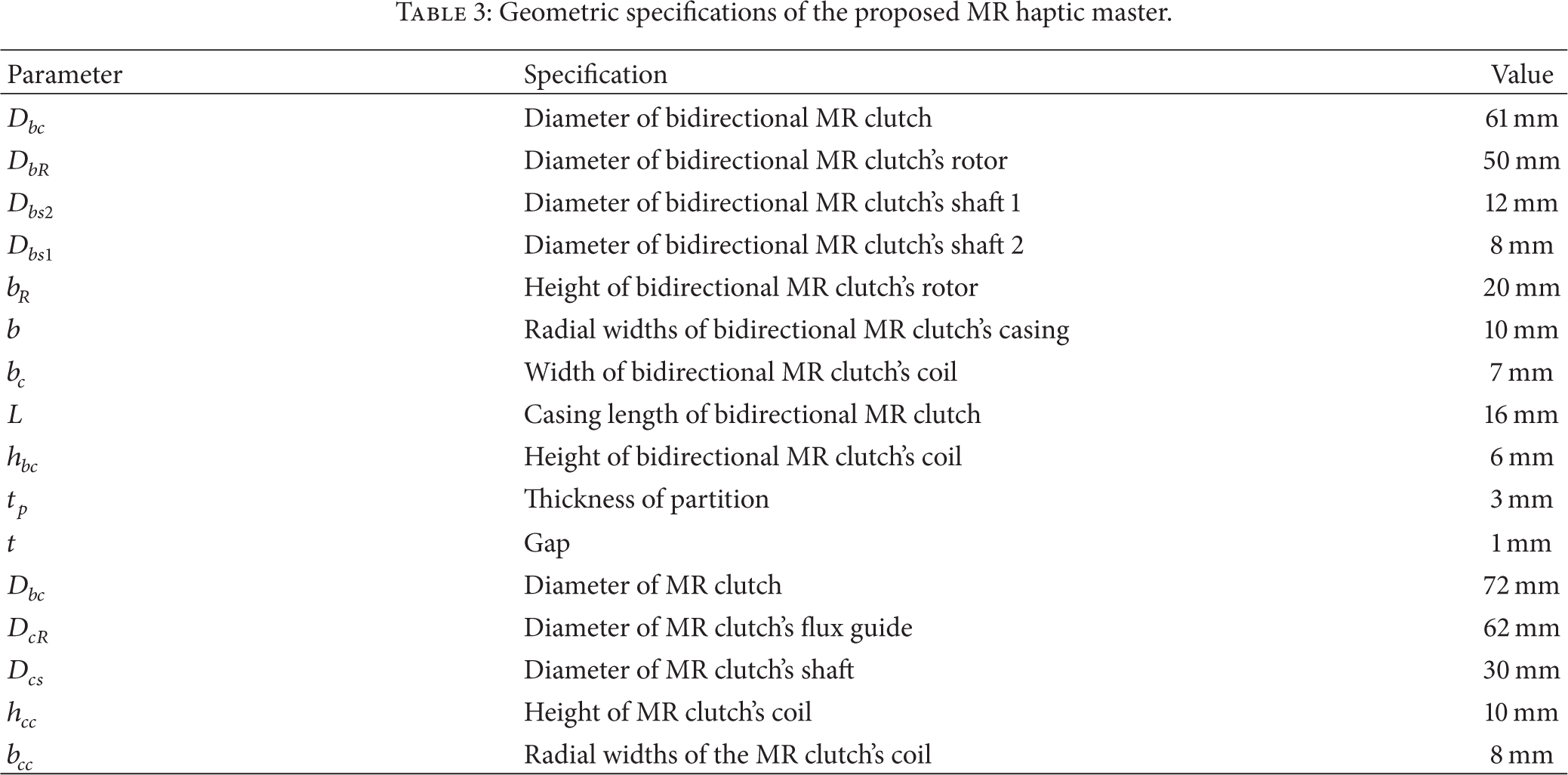
The design variables for MR clutch and their limits are assigned as follows: the diameter of the shaft is set as 25–35 mm, the height of the coil is set as 5–10 mm, and the radial widths of the coil are set as 5–10 mm with 1 mm step size. The obtained FE solutions and calculated torque of the MR clutch are listed in Table 2. Among several results, the diameter of the shaft and the height and radial widths of the coil are determined to be 30 mm, 10 mm, and 8 mm, respectively. Figure 9 shows the magnetic density of the MR clutch with the obtained optimal dimensions when a current of 2 A is applied to the coil. The mean magnetic flux densities at the annular face and end face of the rotors are 0.506 T and 0.024 T, respectively. Finally, the 4-DOF MR haptic master with these determined design parameters was manufactured as shown in Figure 10. All significant dimensions for the manufactured clutches are given in Table 3.
Predicted torque of MR clutch according to varying design parameters.

Geometric specifications of the proposed MR haptic master.
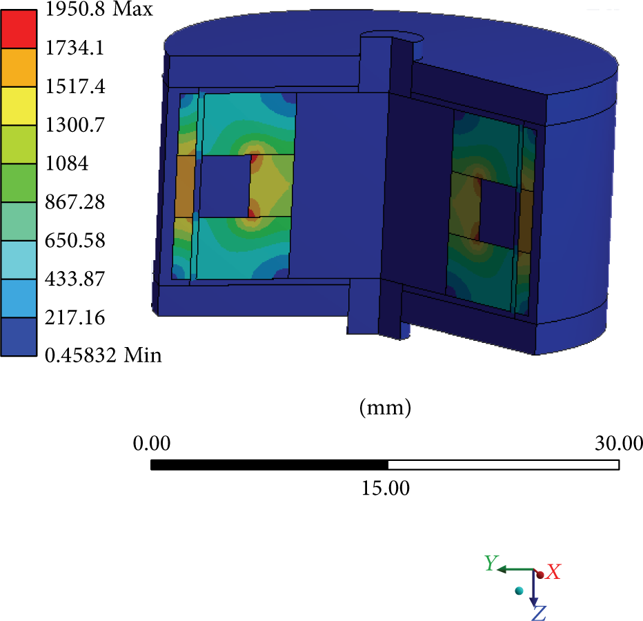
Magnetic flux density of the MR clutch with optimal dimensions.
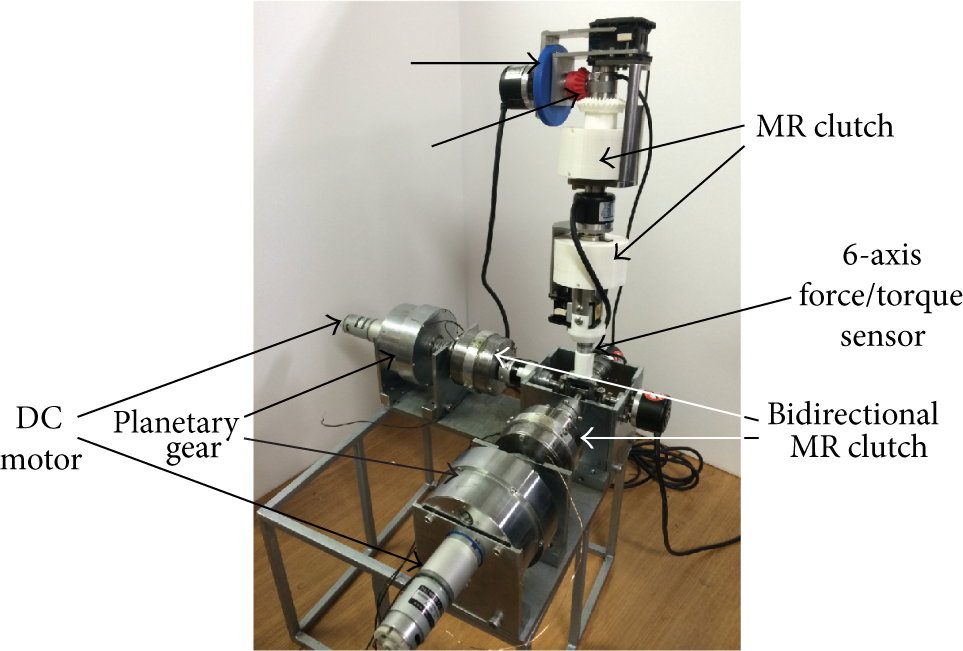
Manufactured MR haptic master.
4. Performance Evaluation
In order to evaluate the accuracy of the optimal design and torque models, two experiments with the manufactured clutches were undertaken. In the experiment, the torque signal is measured by a torque sensor (Senstech Corp., SDS-100) connected with the shaft of the casing. In addition, two rotor shafts of the bidirectional MR clutch are rotated by a driving DC motor with revolution at 30 rpm and a bioutput gearbox. In order to achieve the maximum repulsive torque in one direction, one coil is excited with the maximum current value, while the other is turned off. The flux guide of the MR clutch is rotated by a driving servomotor with revolution at 30 rpm. Measured signals are converted to a digital signal and transferred to a computer by an NI Express Chassis A/D board (PXIe-1082), which includes a data acquisition board (PXIe-6363).
The measured torque values of the bidirectional MR clutch are plotted in Figure 11(a) for two directions and are stabilized at approximately 1.88 Nm and 1.92 Nm. From FE analysis results and torque modeling analysis for bidirectional MR clutch, simulation values of repulsive torque for two direction are calculated as 1.9 Nm, respectively. From the results, the desired values are slightly different from the measured one. It may be caused by the manufacturing process. However, this difference is not significant. Similarly, as shown in Figure 11(b), the measured torque value of the MR clutch is approximately 2.72 Nm, while the calculated torque value of MR clutch is 2.753 Nm.
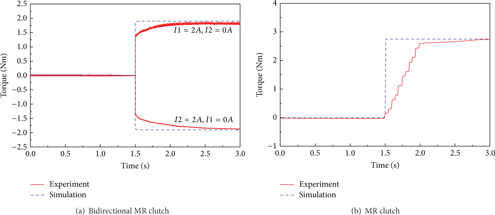
Torque values obtained from experiment and simulation.
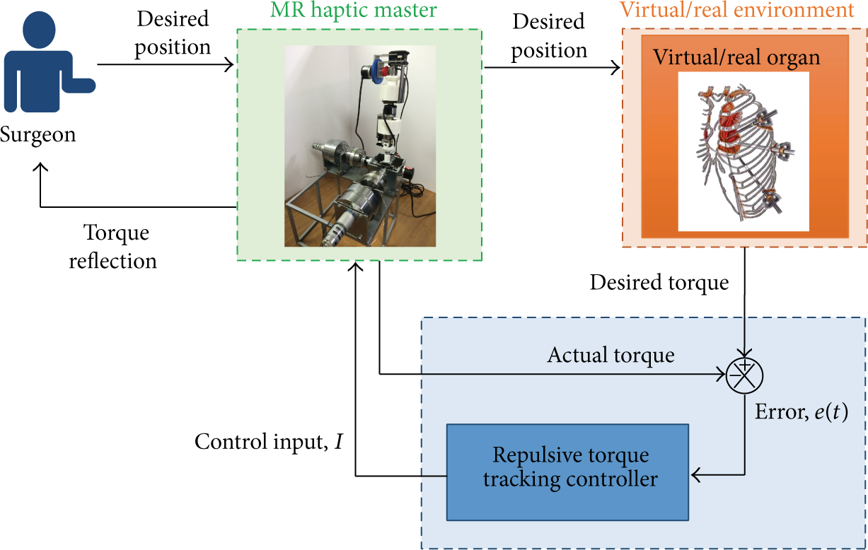
In order to evaluate control performance of the proposed haptic device, an experiment is prepared as shown in Figure 12. It is noted that the algorithm of the virtual or real slave part is not considered in this study. In order to accomplish the desired torque trajectories, in this work, a proportional-integral-derivative (PID) controller is experimentally implemented as follows:
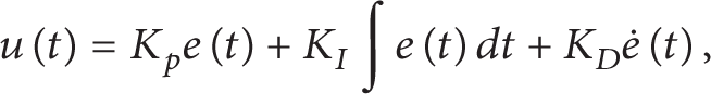
where e(t) is error signal between desired torque signal and actual torque signal measured by a 6-axis force/torque sensor (ATI Corp., Nano17). K p , K I , and K D are the control gains of PID controller. In this work, the gains for PID controller are chosen by 0.3, 0.05, and 0.15, respectively. The control input calculated by the PID control is applied to MR haptic master. During control loop, the following condition is generally imposed. This condition physically means that the implementing of the controller just assures the increment of energy dissipation of the stable system:

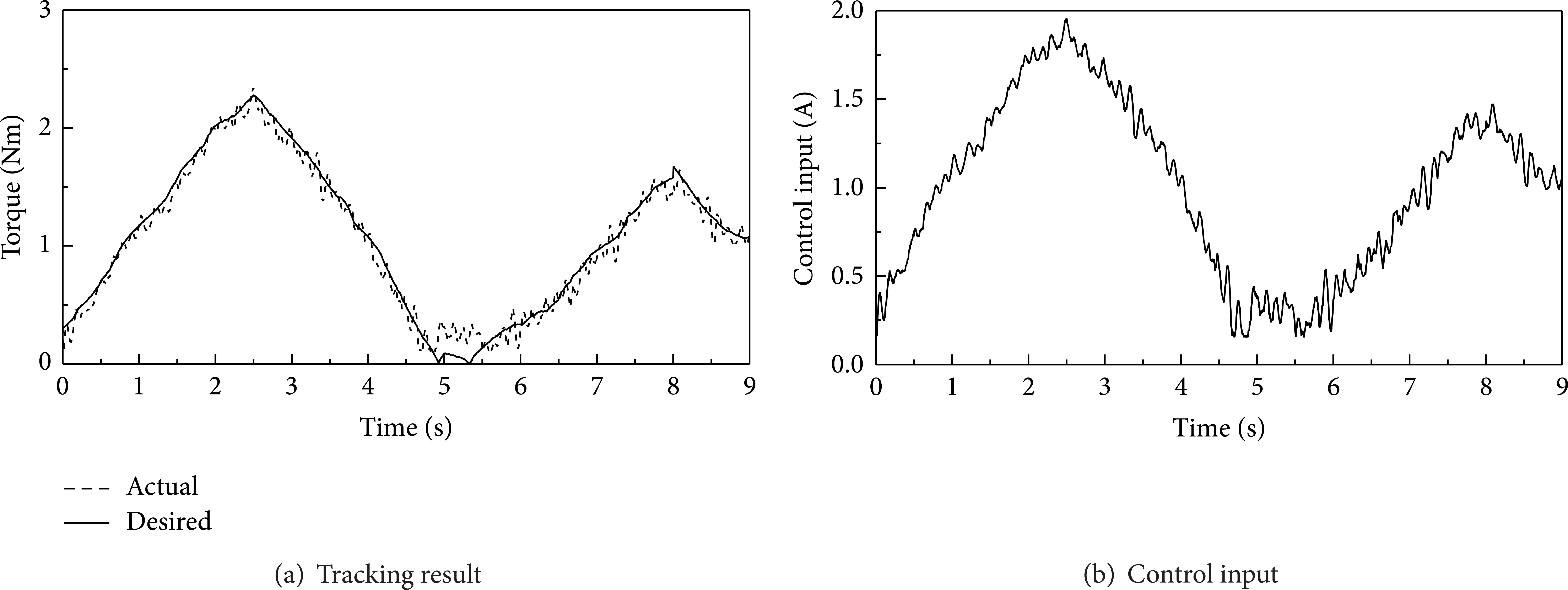
The PID controller is activated in the microprocessor to reflect the desired torque from the virtual slave. Figures 13 and 14 show control results along pitching and yawing motions. By utilizing the bidirectional MR clutch, the control results along pitching motion whose maximum torque is 2.33 Nm are obtained as shown in Figure 13(a). Figure 14(a) shows measured control results of MR clutch whose maximum torque is 2.03 Nm along yawing motions. It is clearly observed that the desired torque trajectories are well tracked by activating the proposed haptic master without substantial tracking errors. It is seen from Figures 13(b) and 14(b) that the input signal applied to the MR haptic master is lower than 2 A. Finally, more detail performance information of manufacture haptic master is listed in Table 4.
Capability specifications of the proposed MR haptic master.

Experimental apparatus for desired torque tracking control.
Repulsive torque tracking control result along pitching motion.

Repulsive torque tracking control result along yawing motion.
5. Conclusion
In this work, a novel 4-DOF haptic master was developed using MR fluid which can be applicable to the RMIS. By using a controllable MR fluid, the proposed haptic device can easily generate bidirectional active torque along 4-DOF directions. After addressing the mechanical configuration of the proposed haptic device, the torque models of the MR actuators were mathematically derived based on the Bingham model of the MR fluid. Using ANSYS, the geometric dimensions of the MR haptic master were optimally obtained to meet the spatial-limitation and torque requirements. Based on the optimal solution of the design procedure, the 4-DOF MR haptic master was manufactured. In order to evaluate the performance of the manufactured haptic device, an experimental validation was conducted. From the experimental results, it has been demonstrated that the proposed haptic master can generate the predicted torque levels required for the RMIS. In addition, the tracking control experiment has been implemented to the proposed haptic master using a simple PID controller. The repulsive torque trajectories were well obtained by activating the haptic master system without causing a significant tracking error. It is finally remarked that the proposed MR haptic master will be incorporated with the surgery robot for RMIS application in the near future. In this future work, the master device and surgery robot will be integrated into the RMIS system in which the repulsive force and desired position originating from the object and operator, respectively, will be transferred to each other.
Footnotes
Nomenclature
Conflict of Interests
The authors declare that there is no conflict of interests.
Acknowledgment
This work was supported by the Incheon National University Research grant in 2013.