
Abstract
This paper presents a novel method for identifying dynamic parameters of robot manipulators with elastic joints. A procedure based on the Lagrangianm formulation of the dynamic model is proposed. Each term is inspected to search for a linear relationship with the dynamic parameters, thus enabling the linearization of robot dynamic model. Hence, the torque vector is expressed as the product of a regressor matrix, suitably defined by the vector of dynamic parameters. A parametric identification based on a least-squares technique is applied to determine dynamic parameters of robots with elastic joints. The correctness of the proposed procedure has been tested in simulation on two robotic structures with elastic joints of different complexity, that is, a 2-degree-of-freedom (dof) and a 6-dof manipulator, controlled with a PD control in the joint space.
1. Introduction
Robot dynamics describes the relationship between motion and forces by means of a number of parameters, including link and motor masses, inertias, and friction. Dynamic parameters can be grouped into the following three main categories, based on the contribution they provide to generate motor torques [1]:
unidentifiable parameters: if a variation of the parameter does not modify the robot dynamic behavior;
linearly independent parameters: if a variation of the parameter modifies the robot dynamic behavior in a way that is not repeatable by varying another parameter (or a set of other parameters);
linearly dependent parameters: if a variation of the parameter modifies the robot dynamic behavior in a way that is repeatable by varying another parameter (or a set of other parameters).
The knowledge of robot dynamic parameters is helpful for simulation purposes [2], for control purposes [3, 4], and for mechatronic design purposes (i.e., to optimize robot design by studying the interaction between the robot and its environment [5]). Notwithstanding, a proper estimation is often unavailable. Hence, the need emerges of resorting to methods for estimating them; for clarity, a schematic classification of these methods is provided in Figure 1, with a brief description.
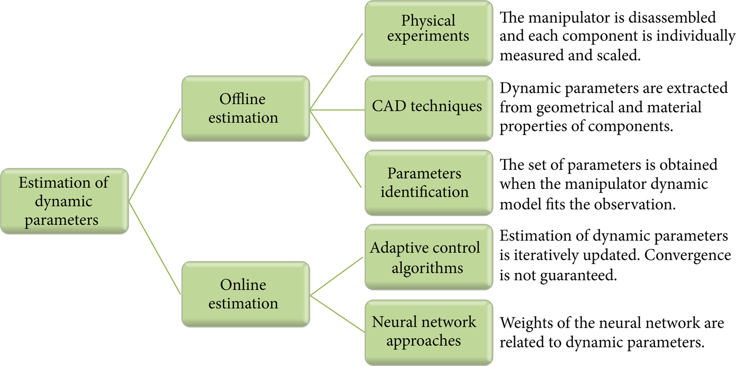
Methods for dynamic parameters identification (readapted from [26]).
This paper is focused on one specific branch of the tree in Figure 1, that is, the Parameters identification procedures belonging to the category of offline estimation.
They consist of “exciting” the dynamics of a manipulator making it move along optimized trajectories through proper torque commands [1, 6]. These methods are generally used to identify parameters of open kinematic chains, generally neglecting coupled dynamics and transmission elasticity. They are grounded on three possible approaches. The first approach exploits the Newton-Euler formulation (N.-E.) of the dynamic model [1, 7, 8]. The second approach is based on the Lagrangian formulation of the dynamic model [9, 10]. The third one exploits again energetic considerations [11, 12], as in the second approach based on the Lagrangian formulation. However, it evaluates the energy of each configuration without relating the external torques to the Lagrangian of the system. In [13] a comparative analysis of the computational burden of the Lagrangian formulation with respect to the energetic formulation is provided.
All the aforementioned approaches are formulated for robots with rigid joints and links and cannot be easily extended to the case of robots with mechanical elasticity because of the different dynamic model. On the other hand, when existing, elastic phenomena cannot be neglected because of the degradation of robot performance they may cause [3, 14, 15].
It is worth noticing that only a few works cope with the identification of the elasticity in single joints due to the transmission systems and, to our knowledge, no work does exist on the identification of the complete dynamics of robots with mechanical elasticity. For instance, in [16] a method to estimate one actuator elasticity is proposed, but motor inertia is supposed to be known. The work in [17] presents the parameter identification of one elastic joint based on a nonlinear model, and at least four series of experiments are needed to apply the proposed approach.
This paper intends to propose a novel procedure for identifying the dynamic parameters of robots with elastic joints. It is grounded on the Lagrange formulation of the dynamic model of the manipulator, thus accounting for robot elastic energy in addition to kinetic and gravitational energy contributions. Open kinematic chains and absence of coupled dynamics are supposed. Furthermore, joint elasticity is assumed to be concentrated in the transmission system between the motor and the joint. This entails that 14 dynamic parameters should be estimated for each joint. They are link mass, three coordinates of the center of mass, six components of the inertia tensor, motor inertia, static and viscous friction coefficients (assuming the Coulomb friction model for static friction), and transmission elasticity. Special attention is paid to the extraction of the regressor matrix, in order to linearize robot dynamic model and facilitate parametric identification. Also a method is proposed to identify the category to which a parameter belongs (i.e., unidentifiable, linearly dependent, or else independent).
The paper is structured as follows. Section 2 introduces the notation that is adopted in this paper. In Section 3, linearization of robot dynamic model with respect to dynamic parameters is presented. The regressor matrix relating external and actuation torques with dynamic parameters is extracted in Section 4. Parameter identification is carried out in Section 5; it also proposes a method to discriminate the category to which a parameter belongs. Finally, the proposed procedure is validated on two simulated robots (a planar and a 6-dof robot) in Section 6. Section 7 summarizes the main achievements of this work, presenting conclusions and future works.
2. Notation
In this paper, the following notation is used. All the parameters are defined in the robot base frame, that is, “0” frame, if not specified by other apexes. Regarding kinematic parameters we have the following:
θ
i
: angular position of motor i, divided by reduction gear
q i : angular position of link i, which is different from θ i due to transmission elasticity;
For defining robot dynamic parameters, it is useful to introduce the concept of “body.” Body i is the system composed of link i and the stator of the motor rigidly connected to it. Thus, the following notation applies to dynamic parameters:
m i : mass of body i;
Υ i : inertia of rotor of motor i;
K i : elasticity of transmission i;
3. Dynamic Model of Robot Manipulators with Elastic Joints
The following assumptions are provided:
The robot has an open kinematic chain of rigid bodies, driven by electrical actuators through elastic joints undergoing small deformations in the domain of linear elasticity.
Rotors of motors are rigid bodies with uniform density around their rotation axes.
Stator of motor i is rigidly connected to joint i − 1.
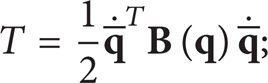
Robot kinetic energy T, gravitational potential energy U g , and elastic potential energy U e can be computed as follows:

where n is the number of robot joints and
By applying the Lagrangian formulation, dynamic model of robots with elastic joints can be expressed as [3, 21]

where
matrix

being operator asym(
the generalized static and viscous friction matrices


where U
e
is the elastic potential energy and
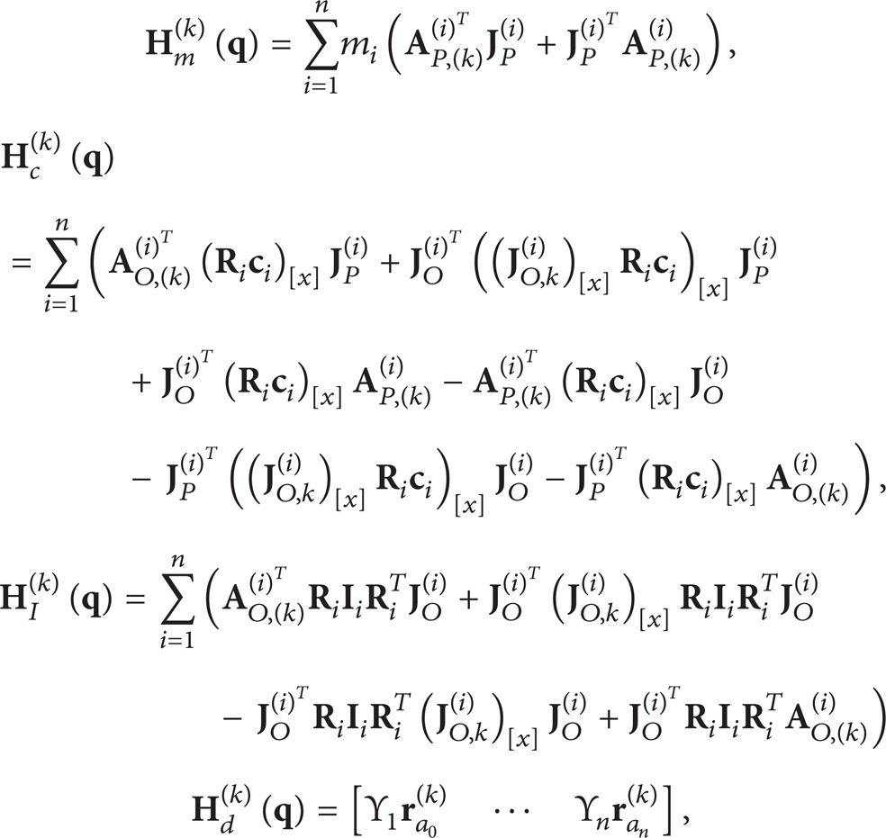
As shown in Appendix A, by exploiting the relationships between linear and angular velocity with joint velocity, inertia matrix

where
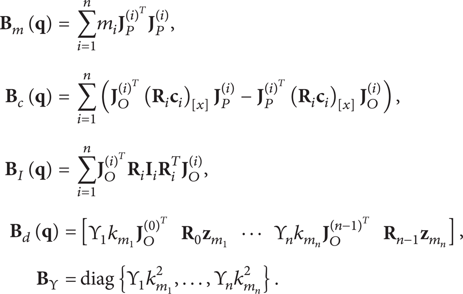
Symbol (·)[x] denotes the skew-symmetric matrix corresponding to the cross product. Also note that (·)[x]
T
= − (·)[x].
It is worth observing that submatrix
Once matrix
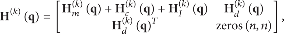
where
being

and
Finally, coefficient j of gravity vector

where
4. Linearization of Robot Dynamic Model
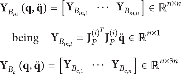
Formulation of robot dynamics as in Section 3 makes each term depend only on one dynamic parameter. This has the consequent advantage of simplifying the linearization of the dynamic model and the evaluation of regressor matrix

where

is the parameter vector composed of the subvectors of mass parameters
In the following the expression of the regressor matrix related to each term of the dynamic model is presented.
First, product
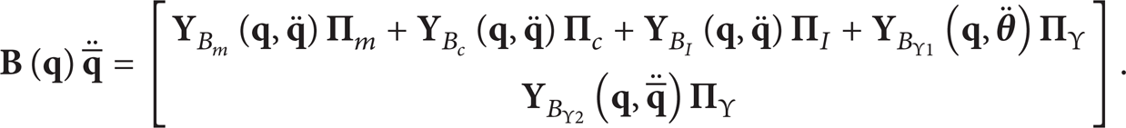
The regressor matrices in (15) can be obtained from (8) as 1


From (16)–(20) it follows that
Consequently, product

Analogously, product

where

where


where vectors
As regards the remaining conservative terms, that is,

where

being both

On the other hand,


5. Parametric Identification Procedure
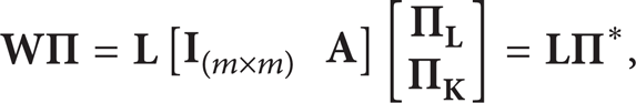
A parametric identification procedure for robots with elastic joints is proposed to identify vector of dynamic parameters
or, alternatively,

where

If matrix

where
Otherwise, if rank of matrix
If column i of matrix
If column i of matrix
If column i of matrix
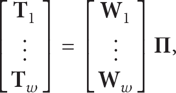
In order to evaluate whether parameters are independently identifiable or not, Gauss-Jordan elimination procedure can be applied to evaluate a base matrix

where m is the number of vectors composing the base of
Eventually, by grouping vector

and, due to relation (39),
where
Further, vector
6. Validation and Results
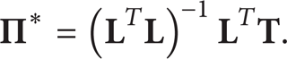
Simulation tests have been performed to validate the proposed identification procedure of dynamic parameters on robots with elastic joints. To this purpose, two robotic structures of different complexity have been modeled. The former is a planar manipulator with 2 dofs and elastic joints (see Figure 2). The latter is a 6-dof manipulator modeled as a PUMA 560 with additional elastic joints.
2-dof planar robot with elastic joints. Gravity vector is directed along − y0 axis.
The planar manipulator moves in the vertical plane; hence, gravitational acceleration
Kinematic and dynamic parameters of the planar robot are as follows: a1 = a2 = 0.5 m (a
i
: link length), l1 = l2 = 0.25 m (l
i
: center of mass distance; see Figure 2), m1 = 20 kg, m2 = 10 kg (m
i
: link mass),

where

In accordance with model in (5), only the static and viscous components of the friction torque are taken into account, thus neglecting the nonlinear effects as shown, for example, in Figure 3 for the Coulomb friction. In the identification procedure, static and viscous components will be identified (as shown in (32) and (33)), while the nonlinear effects will be regarded as external disturbances.

Complete (Stribeck) friction model [22] and Coulomb friction model.
The computed body parameters are given by

The PD control proposed in [3] has been used to control robot motion in the free space. Excitation trajectories based on fifth order B-splines, as in [23], have been used as reference trajectory for each joint.
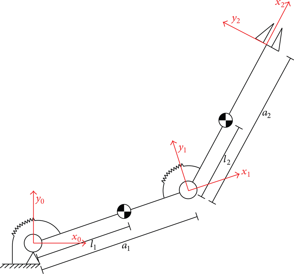
Joint angular positions have been sampled at 1 kHz and quantized to simulate a real scenario, by assuming to have a high resolution encoder (1250000 counts/round). Data have been filtered through a Butterworth IIR low-pass filter of fifth-order and cut-off frequency of 20 Hz. Motor and joint angular velocities and accelerations have been computed through a first-order numerical differentiation. Additionally, the effect of sensor noise on the performance of the proposed identification procedure has been evaluated. To this purpose, a Gaussian noise with zero mean value has been added to motor and joint position, velocity, and acceleration and the error percentage between real and estimated dynamic parameters has been measured for five different levels of signal-to-noise ratio (i.e., SN = 20, SN = 70, SN = 80, SN = 100, and SN = 200), in addition to absence of noise. Motion variables have been obtained by means of the robot forward dynamics also accounting for the friction model in (43). In Figure 4 motor torques applied to the simulated manipulator are shown, with the corresponding motion in the joint space. As shown in Figure 5, the maximum difference between link and motor position is 0.39° and 0.10° for first and second joint, respectively.

Actuation torques for the 2-dof planar manipulator have been generated with the PD control in [3]; corresponding robot motion in the joint space is shown.
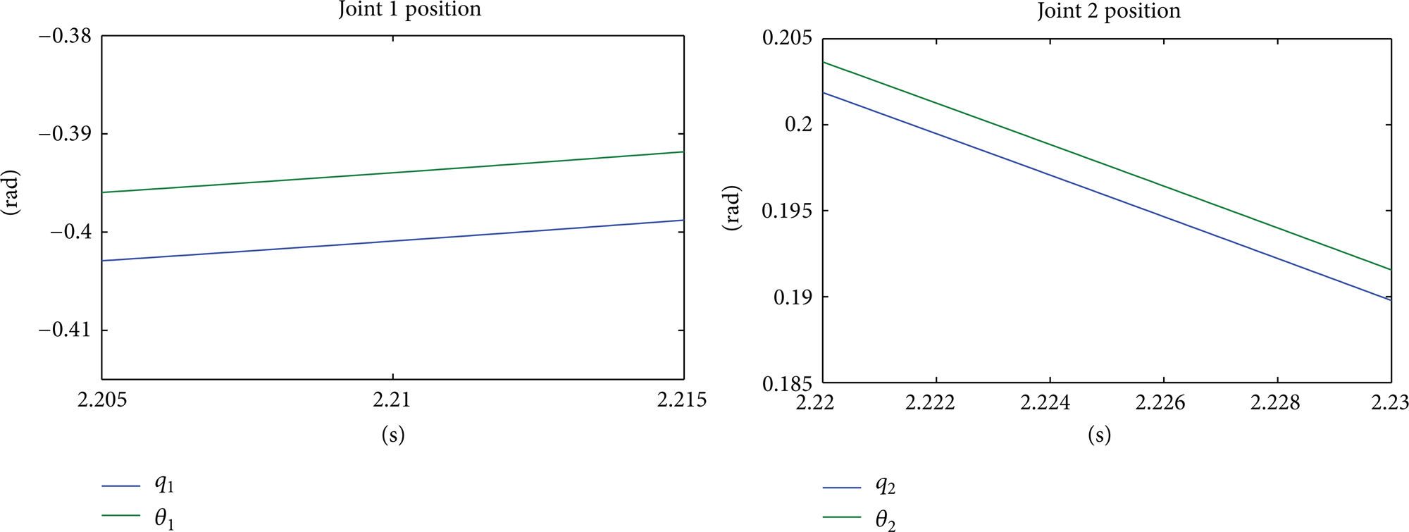
Zoom on the main differences between motor and link positions for the 2-dof planar manipulator.
A total of 8900 measurements have been performed, thus constructing observation matrix
Results of the identification procedure.

As one can easily observe in Table 1, the error between the obtained estimated parameters and the real ones is very low. The normalised mean error is 0.103; it becomes 0.00862 (i.e., 0.862 per cent as percentage error) without the static friction, thus pointing out that probably the neglected nonlinear terms of the adopted model may cause an increase of the error. Furthermore, Table 2 reports the normalised mean error between the estimated parameters and the real ones in the case of noisy measurements of position, velocity, and acceleration, for five different levels of signal-to-noise ratio (i.e., SN = 20, SN = 70, SN = 80, SN = 100, and SN = 200). One can observe that for high values of signal-to-noise ratio, up to SN = 80, the error still remains small and comparable to the absence of noise. For lower values of signal-to-noise ratio, the error becomes very high.
Variation of the estimation error with signal-to-noise ratio.

As aforementioned, the proposed identification procedure of dynamic parameters has also been applied to a 6-dof robot manipulator with elastic joints. It has been modeled as a PUMA 560 with elastic joints. Robot dynamic parameters (except for joint elasticity) are reported in [25]. On the other hand, transmission elasticity for each joint has been assumed to be as K i = 2000 N·m/rad for i = 1, …, 6.
By analogy with the planar case, excitation trajectories based on fifth-order B-splines have been planned in the joint space and the PD control in [3] has been used to regulate robot position. Motor torques applied to the simulated manipulator and resulting motion in the joint space are reported in Figure 6. For brevity, only the maximum difference between link and motor position for joints 1 and 2 is shown in Figure 7. However, the mean value over the six joints resulted to be 0.09 rad.
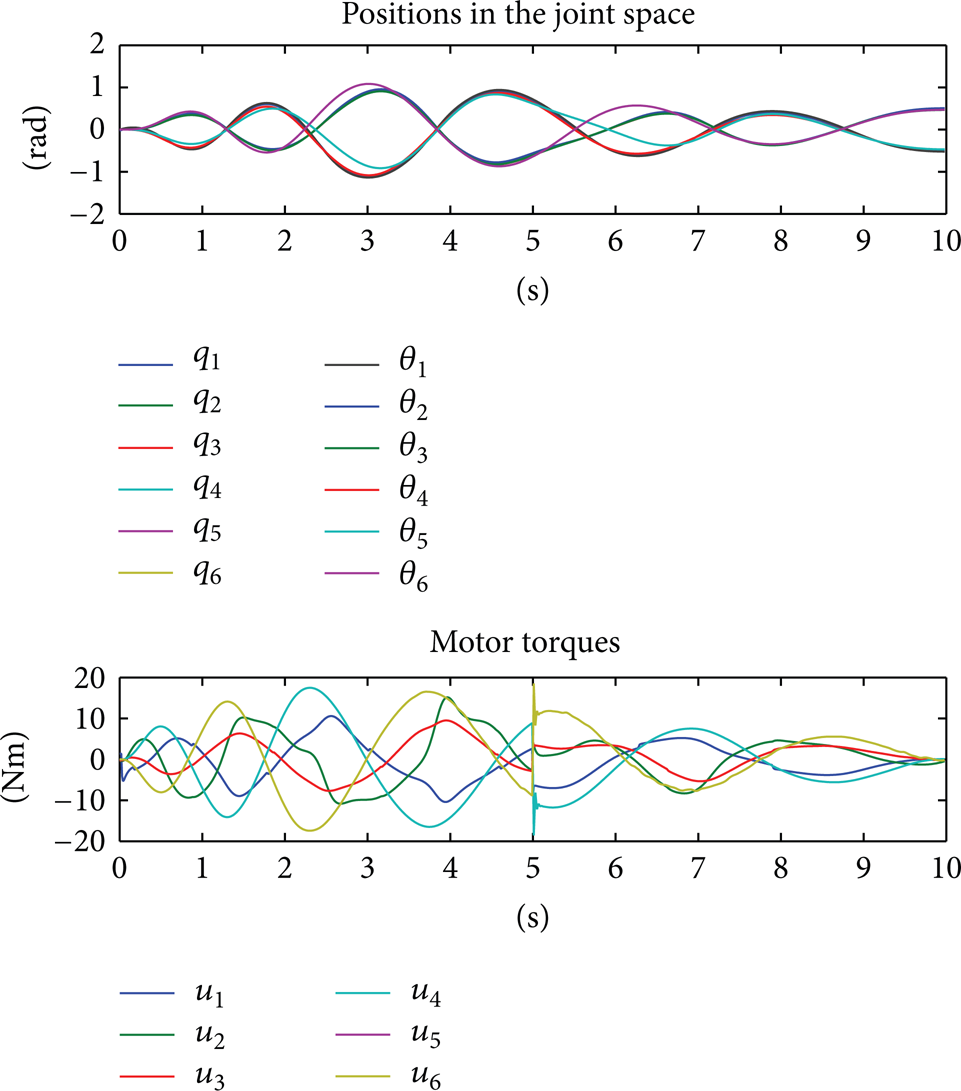
Actuation torques for the 6-dof manipulator have been generated with the PD control in [3]; corresponding robot motion in the joint space is shown.

Zoom on the main differences between motor and link positions for the 6-dof manipulator.
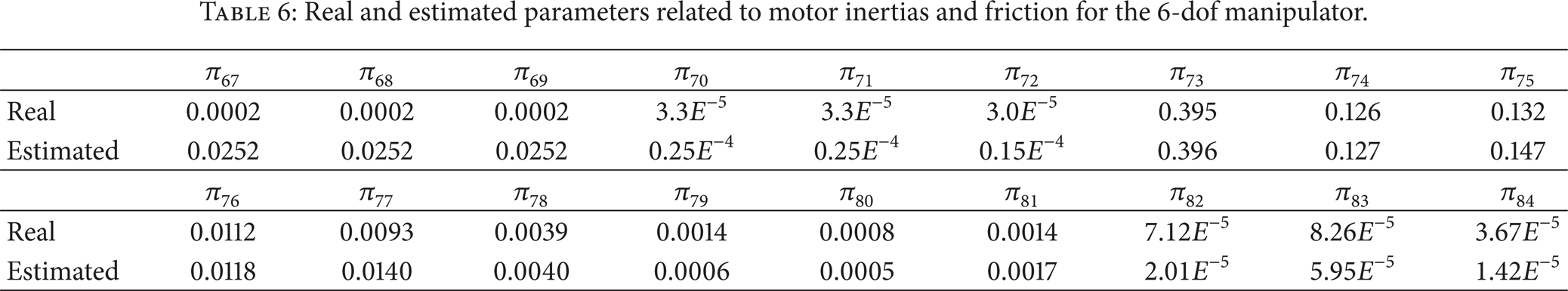
As for the planar case, observation matrix
Real and estimated parameters related to joint elasticity and masses for the 6-dof manipulator.

Real and estimated parameters related to the centers of mass for the 6-dof manipulator.

Real and estimated parameters related to the inertia tensors for the 6-dof manipulator.

Real and estimated parameters related to motor inertias and friction for the 6-dof manipulator.
7. Conclusions
A novel procedure for identifying dynamic parameters for robots with elastic joints has been proposed. The proposed procedure is based on the Lagrangian formulation of the dynamic model of the manipulator, accounting for robot elastic energy, in addition to kinetic and gravitational energy contributions. This feature represents the actual main novelty of this work, since no systematic approaches for parameter identification have been reported in the literature for robots with elastic joints.
Each term of the dynamic model has been analyzed in order to linearize it and express the vector of external and motor torques as the product of a regressor matrix by a vector of dynamic parameters to identify. Special attention has been paid to the extraction of the regressor matrix, in order to facilitate parametric identification. Also a method is proposed to identify the category (unidentifiable, linearly dependent, or else independent) to which a parameter belongs. Two robotic structures with elastic joints of different complexity have been simulated in order to validate the procedure of parametric identification, that is, a 2-dof planar manipulator and a 6-dof manipulator. The PD control in [3] has been used to move the robot in the free space; the simulation of the forward dynamics of the manipulator has permitted to collect joint and motor positions, velocities, and accelerations during motion and consequently apply the identification procedure with and without measurement noise.
The obtained results have shown that the proposed procedure leads to a correct identification of the manipulator dynamic parameters with a very low error; the mean normalised error between actual parameters and estimated ones is 0.103 for the planar manipulator and 0.123 for the 6-dof manipulator. The percentage error decreases to a value around 0.862 percent if the static friction is excluded (which is more affected from the neglected nonlinearities of the adopted friction model). In presence of measurement noise, the error is still low for signal-to-noise ratios higher than 80. The correctness of the analytical formulation of the regressor matrix and, consequently, of the parametric identification procedure is thus assessed and the application on a real robot with elastic joints can be envisaged as future activity.
Conflict of Interests
The authors declare that there is no conflict of interests regarding the publication of this paper.
Footnotes
Appendices
Authors' Contribution
Loredana Zollo and Edoardo Lopez contributed equally to this paper.
1
In (18) and ![]() operator (
operator (
Given a (3 × 3) symmetric matrix