
Abstract
This paper focuses on the telescope gain affected by a multilevel hybrid mechanism for the feed positioning in the five-hundred-meter aperture spherical radio telescope (FAST) project, which is based on the positioning accuracy analysis of the mechanism. First, error model for the whole mechanism is established and its physical meaning is clearly explained. Then two kinds of error sources are mainly considered: geometric errors and structural deformations. The positioning error over the mechanism's workspace is described by an efficient and intuitive approach. As the feed position error will lower the telescope gain, this influence is analyzed in detail. In the end, it is concluded that the design of the mechanism can meet the requirement of the telescope performance.
1. Introduction
Five-hundred-meter aperture spherical radio telescope (FAST, Figure 1) now being constructed in Southwest China will be the largest single dish telescope in the world as the diameter of its main reflector is 500 m [1, 2]. A multilevel hybrid mechanism is designed to carry feeds and receivers moving at the height of 140 m above the main reflector. It is also responsible for accurate feed positioning for astronomical observation tasks [3, 4]. As shown in Figure 2, this mechanism has three levels: a long-span cable-driven parallel manipulator (CPM, the first level), an AB rotator (the second level), and a rigid parallel manipulator (typically Stewart manipulator [5], the third level). They are assembled in series. The feeds and receivers are installed at the terminal of the whole mechanism (the end effector of Stewart manipulator, called S-platform). The first level is used to realize large-scale movement for observation tracking [6]. Given the fact that CPM cannot provide enough orientation angles, AB rotator is introduced here to further compensate observation angles. Stewart manipulator is for fine adjustment of the feeds’ position and therefore the position accuracy can meet the telescope requirement.

Artist's impression of FAST.
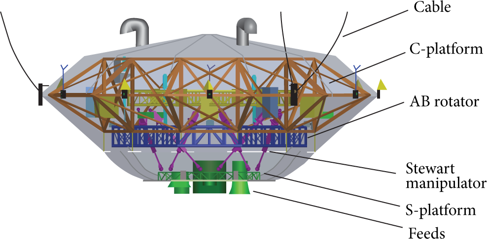
3D model for the mechanism.
The mechanism faces great challenges to achieve required positioning accuracy as follows.
CPM is a large-span flexible parallel mechanism, which has six cables driving a movable platform named C-platform. CPM's stiffness is low and the pose (position and orientation) of C-platform can be easily influenced by wind forces, time-varying function of the mechanism's barycenter, and other external disturbances [7–9]. So significant error is induced in the first level.
Main components of the mechanism adopt truss structure with large geometry size. For example, the maximum size of C-platform is 12.62 m and that of AB rotator is 8.898 m. Their stiffness is therefore limited. On the other hand, the total weight of this mechanism with the installed equipment is about 30 tons, so external forces imposed on these components are large, which make the components deflected.
Geometric errors (mainly caused due to manufacturing, assembling, actuating, etc.) must be taken into consideration. Moreover, coupling motion and interaction between different levels complicate the analysis to the mechanism error.
Positioning accuracy of this mechanism determines the position and orientation of the feed. Pose deviation of the feed will change the antenna pattern and lower the gain of the telescope. This paper firstly investigates error modeling and accuracy analysis of the hybrid mechanism and then the relation between feed pose and telescope gain. In the end our simulation results show that the design can satisfy the requirements of the telescope performance.
2. Mechanism Describing and Error Modeling
2.1. Coordinate Frames Setting
Since CPM is a large-span cable-driven parallel mechanism, the pose of C-platform can be easily affected by the external disturbance. Error from this level mechanism is substantial, and the estimated maximum value is around 100 mm. However, this error can be compensated by the third level mechanism since Stewart manipulator is suitable for fine adjustment [10]. This paper only considers errors caused by the second and third levels. Choose coordinate frame of C-platform {C}:O-XYZ as a global coordinate system.
Structure of the mechanism and corresponding coordinate frames are described in Figure 3. AB rotator consists of AB-ring, two orthogonal axes (named as A-axis and B-axis), and two legs (denoted as A-leg and B-leg). Each leg is extensible and driven by a servomotor and a lead screw. C-platform and AB-ring are connected through B-axis and B-leg. B-leg is installed at a certain distance away from B-axis to convert the driven force of B-leg to driven moments. When B-leg extends, AB-ring is driven to rotate around B-axis. {F}:O1 -X1 Y1 Z1 is the local coordinate frame for AB-ring.

Coordinate frames for the feed cabin.
Stewart manipulator includes a base (S-base), six extensible legs (S-leg), and a movable platform (S-platform). S-base is connected to AB-ring through A-axis and A-leg. Similarly, when A-leg extends, Stewart manipulator is driven to rotate around A-axis. The local coordinate frames {B}:O2-X2 Y2 Z2 for S-base and {P}:O3-X3 Y3 Z3 for S-platform are shown in Figure 3, respectively. Joints B i (i = 1, 2, …, 6) on S-base are used to connect S-leg and S-base, while joints P i (i = 1, 2, …, 6) on S-platform are used to connect S-leg and S-platform.
2.2. Error Modeling
The vector chain model is established for each S-leg as shown in Figure 4. The vector of the ith (i = 1, 2, …, 6) S-leg (from joint B
i
to joint P
i
)

where

Vector chain for jth S-leg.
Using S-leg length, L
i
, and the directional unit vector

where

From (2), one can see that leg actuation errors (δ
3. Error Analysis
Monte Carlo method is usually applied for error analysis of a parallel mechanism [12]. It acquires random sampling from every error source and plots error boundary if there are enough samples. But it is at cost of heavy computation. As for a multilevel hybrid mechanism, there are more error sources than single parallel mechanisms, so Monte Carlo method may not be a good choice. Based on vector set theory and linear algebra method, this paper uses an efficient and intuitive approach to explore the terminal error boundary.
The error model includes two kinds of error sources: geometric error and deformation error. Geometric error relates to manufacturing and assembling process and actuation for the extensible legs. According to manufacturing and assembling experience, the maximum value of both joint position errors and actuation errors is 0.1 mm. So the first two terms on the right side of (2) can be expressed as
If

then

Based on linear algebra, δ
In the error model, the maximum error due to deformation is a definite vector, which can be analyzed by finite element method using structure analysis software. Note that the absolute value of deformation of these truss structures is irrelevant to the terminal error. Because pose calibration will be done at the beginning, so only the difference between the initial deformation and the largest deformation is considered in this study.
The error boundary can be described by convex hull in MATLAB simulation. It is wrapped by parallelograms and triangles as shown in Figure 5. Maximum errors in each direction are 1.12 mm in X-direction, 3.28 mm in Y-direction, and 3.93 mm in Z-direction, respectively, as shown in Figures 5(b) and 5(c). The total maximum position error is 4.99 mm (−0.53 mm, −3.28 mm, and 3.72 mm separately in X-, Y-, and Z-direction). Similarly the maximum orientation error is 0.036 degree.

Terminal position error boundary.
4. Telescope Gain Loss Induced by Feed Position Error
4.1. Relation between Telescope Gain and Feed Position
Pose error of the terminal of this mechanism will induce the feeds’ position deviation or illumination deflection, which finally results in gain loss of the telescope. Receivers of FAST are designed to cover the frequency range from 70 MHz to 3 GHz [1]. Higher operational frequency requires more accurate positioning of the feeds. So telescope gain loss is only analyzed at 3 GHz in this work.
The effects of the feed position error on the telescope gain are in the following three ways.
If the feed shifts away from the focus (but still on the focus plane, X-Y plane in this paper), the direction of the telescope maximum gain will offset from the principal axis of the telescope; that is, the direction of the maximum gain does not point to the observed radio source. For example, if the feed center shifts 1 cm, 2 cm, and 3 cm away, respectively, from the origin (0 cm) along with X-direction, the telescope gain patterns are shown in Figure 6 (on the right side of Figure 6 are the details of the gain around zero degree) and the telescope gain variations are listed in Table 1. It is indicated that the more shift from the origin, the more gain loss. Gain loss at 1 cm offset is the maximum allowable value in FAST project.
If the feed shifts away from the focus plane and moves along telescope's principal axis (Z-axis in this paper), the feed will be above or below the focus; therefore, illumination phase is changed and further lowers the telescope gain. Figure 7 depicts the telescope gain patterns in this case (on the right side of Figure 7 are the details of the gain around zero degree). The telescope gain variations are listed in Table 2. Again, it is indicated that the more shift from the origin, the more gain loss. Gain loss at 3 cm offset is the maximum acceptable value in FAST project.
If the feed orientation is changed, the distribution of illumination over the main reflector is changed accordingly so that the telescope gain is affected. As the rotation angle of the illumination direction increases, the telescope gain decreases as shown in Figure 8 (on the right side of Figure 8 are the details of the gain around zero degree) and Table 3. When the angle is 10 degree, the gain loss is 3.284%, which is acceptable.
Telescope gain variations at zero degree (with position shift in X-direction).

Telescope gain variation at zero degree (with position shift in Z-direction).

Telescope gain variation at zero degree (with illumination direction rotation).


Telescope gain patterns (with position shifted in X-direction).

Telescope gain pattern (with position shift in Z-direction).

Telescope gain pattern (with illumination angle varying).
4.2. Gain Loss Induced by the Mechanism Positioning Error
In Section 3, positioning error of this mechanism is analyzed. According to engineering experience and considering the accuracy of control system [13], the terminal error in practice should be three times larger than the results analyzed above. So errors’ influence on the telescope gain loss is analyzed as long as error in X-direction is 3.5 mm, in Y-direction is 10 mm, and in Z-direction is 12 mm. As mentioned above, the maximum value of orientation angles error of the terminal is far less than one degree so that its influence can be ignored.
Figure 9(a) shows the telescope gain around zero degree when feed is at origin and is shifted 3.5 mm in X-direction. One can see that the gain varies from 78.276 dB to 78.246 dB at zero degree. The variation due to feed shift is 0.03 dB, that is, 0.688%. Figure 9(b) shows the case in which feed shifted 10 mm in Y-direction. The gain varies from 78.276 dB to 78.012 dB at zero degree. And the variation is 0.0264 dB, 5.9%. Figure 9(c) shows when feed is shifted 12 mm in Z-direction, the gain varies from 78.276 dB to 78.241 dB. The variation in this case is 0.035 dB, 0.80%. Figure 10 depicts telescope gain affected by all positioning errors; that is, feed is shifted 3.5 mm in X-direction, 10 mm in Y-direction, and 12 mm in Z-direction. The gain varies from 78.276 dB to 77.973 dB at zero degree. The total gain loss is 0.303 dB, 6.74%. In summary, the dominant factor is the case in which feed shifted 10 mm in Y-direction.

Telescope gain pattern.

Telescope gain pattern (3.5 mm shift from X-direction, 10 mm shift from Y-direction, and 12 mm shift from Z-direction).
5. Conclusion
Based on the error model of the hybrid mechanism and its terminal error analysis, this paper focuses on the relationship between terminal error of the multilevel hybrid mechanism and telescope gain. It is concluded that the feed shift in different direction has negative effect on telescope antenna gain. The dominant factor is from the case in which feed shifted 10 mm in Y-direction. The total gain loss due to all position errors is about 6.74%. That gain loss is acceptable for our astronomical observation. So the three-level hybrid mechanism design can be applied in the FAST project.
Conflict of Interests
The authors declare that there is no conflict of interests regarding the publication of this paper.
Footnotes
Acknowledgments
This work was supported by China Ministry of Science and Technology under Grant no. 2013CB837900, the National Science Foundation of China under Grant no. 11261140641, and the Chinese Academy of Sciences under Grant no. KJZD-EW-T01. The authors also appreciate the Open Project Program of the key Laboratory of Radio Astronomy, Chinese Academy of Sciences.