
Abstract
The dimensions, area densities, and geometry of macroscale surface textures may affect the performance of hydrodynamic lubrication interface. Reported in this paper are the investigations of the effect of surface textures bottom shapes on the friction forces between piston ring and cylinder liner for two-stroke marine diesel engine, using numerically generated textures and average Reynolds equation. These textures are on the cylinder liner surface in the form of circumferential oil grooves with different aspect ratios and different area densities. The hydrodynamic pressure distribution is also calculated using Reynolds boundary condition. The results revealed that the bottom shape could positively affect the friction between moving surfaces, as it could provide a microwedge or microstep bearing that tends to enhance the lubrication condition between piston ring and cylinder liner.
1. Introduction
Mechanical energy absorbed by piston ring-cylinder pair in piston engines accounts for the largest portion of efficiency losses due to mechanical friction [1]. About 40% of total energy losses result from engine friction and wear loss, about 25% of these losses is consumed in piston ring-cylinder liner tribosystem [2]. Hence, friction and wear must be reduced to improve fuel consumption. Coating the surface of piston ring or cylinder liner with a protecting material such as zinc phosphate could improve their tribological performance [3]. Surface texturing is also a widely used approach to improve the tribological performance of the mechanical components [4, 5]. Since the 1960s, Hamilton et al. [6] proposed that surface texturing in the form of micro asperities acted as micro hydrodynamic bearings between two parallel surfaces; subsequent studies have investigated the hydrodynamic effect of surface texture. It has been shown that the selective microtexture is effective for generating additional load capacity under hydrodynamic lubrication conditions and the cavitation is the main reason of this phenomenon [7–11]. One of the earliest and most important studies upon that field has been done by Ronen et al. [9]. They developed a theoretical model for lubrication and friction between laser textured flat segments. They concluded that appropriately sized dimples can reduce frictional loss, the effect that has been later confirmed in the experimental work of Ryk et al. [12]. Ryk postulated that the performance gains are due to an increase in converging/diverging pairs, essentially an enhancement of the hydrodynamic potential of the ring face. In the experimental work by Fu et al. [13], the use of laser texturing in the form of microgrooves on cylinder liner could reduce the friction by about 49%, with optimum area density varying from about 5% to 20%, and optimum depth over diameter ratio was about 0.5. Bolander et al. [14] developed a mixed lubrication model to include rough surfaces in a transient elliptical contact typical of piston ring. The results revealed that smaller diameter and deeper dimples with high coverage yielded the reduced cycle-average friction about 55–65%. Takata et al. [15] established a mixed lubrication model of surface texturing on the cylinder liner by introducing the average Reynolds equation. That model assumed the outside part of the surface texturing to be smooth, with either groove or dimple, as the only feature of the surface and the surface roughness are related to dimple (groove) depth. Takata's model did not consider the roughness of nontexturing area. However, in the mixed lubrication region, lubrication and contact conditions do coexist for piston ring-cylinder liner friction pair, causing the coupling effect between surface roughness of contacts area (nontexturing area) and microtexturing area resulting in the influence of film thickness and oil film pressure. At the same time, the external load of piston ring is supported by the asperity contact force from the nontexturing area and oil film pressure force generated by texturing. Based on the Reynolds equation, and dynamic operation conditions of piston ring, Zhou et al. [10] developed a theoretical model for the optimum design of surface texturing on cylinder liner surface. The results showed that, on cylinder liner, texturing with variable parameters in different velocity ranges can be more beneficial than that with invariable parameters. According to Zhou results, the optimum area densities varied from 10% to 22% according to velocity ranges, while the ratio (0.1) could be chosen as the optimum depth over diameter ratio under any operating conditions. Yin et al. [16] developed a mixed lubrication model, on the bases of the average Reynolds equation proposed by Patir and Cheng [17, 18] and Greenwood asperity contact model [19], to study the hydrodynamic effect of cylinder liner spherical microdimples. The obtained optimum area density ranged from 0.2 to 0.4 and the optimum depth over diameter ratio varied from 0.03 to 0.1.
Dimple shape, distribution, and orientation have a noticeable effect on the friction characteristics between sliding surfaces [7, 20]. Nanbu et al. [21] reported investigations of the effects of texture bottom shape and surface relative motion on lubrication enhancement, using numerically generated textures, by means of model-based virtual texturing and numerical simulation. These textures were on one surface of the interacting surfaces. The textures were arranged in a triangular distribution and have the same density. The results suggested that the bottom shapes involving a microwedge and/or a microstep bearing tend to yield thicker oil films. The rectangular shape (flat bottom) groove has provided the most efficient enhancement to the oil film thickness.
Configuration of full stroke texturing on the cylinder liner demands a very large computational mesh; moreover, the relative positioning between piston ring and oil grooves due to the piston ring dynamic requires more complicated computational efforts for a reasonable discretization of the solution domain. That scope of challenge was the main motivation to develop a numerical model in this paper, to study the potential of using cylinder liner macroscale circumferential multiscale oil grooves, with different bottom shapes, to improve the tribological performance of the first compression piston ring of 2-stroke marine diesel engine.
2. The Governing Equation
The oil film pressure distribution along the piston ring surface was calculated, considering the effect of surface roughness in the nontextured areas, by employing the one-dimensional Reynolds equation, derived by Patir and Cheng:
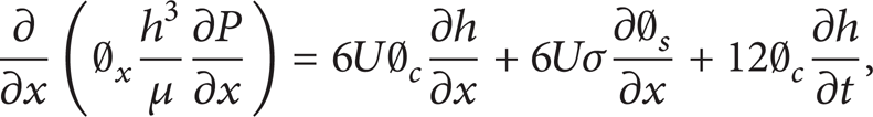
where h is the oil film thickness, P the hydrodynamic pressure, U the ring axial velocity, μ the oil viscosity, σ the composite roughness of the ring face and cylinder liner surfaces, ∅ x pressure flow factor, ∅ c contact factor, and ∅ s shear flow factor. These factors can be referenced from the studies of Patir and Cheng [17, 18].
2.1. Piston Ring Geometry and Cylinder Texturing Mathematical Representation
The nominal film thickness between piston ring and cylinder liner can be expressed as

h m is the time varying minimum oil film thickness (MOFT), and h s is the ring face profile. A flat ring face profile is presented by the combination profile with the straight line and quadratic function of coordinate x which is expressed by the following:

Detailed scheme of piston ring face profile is shown in Figure 1, where b is the axial width of the piston ring. Equation (3) has been developed from Nakai's model [22] in order to express the face profile of a marine diesel engine piston ring.
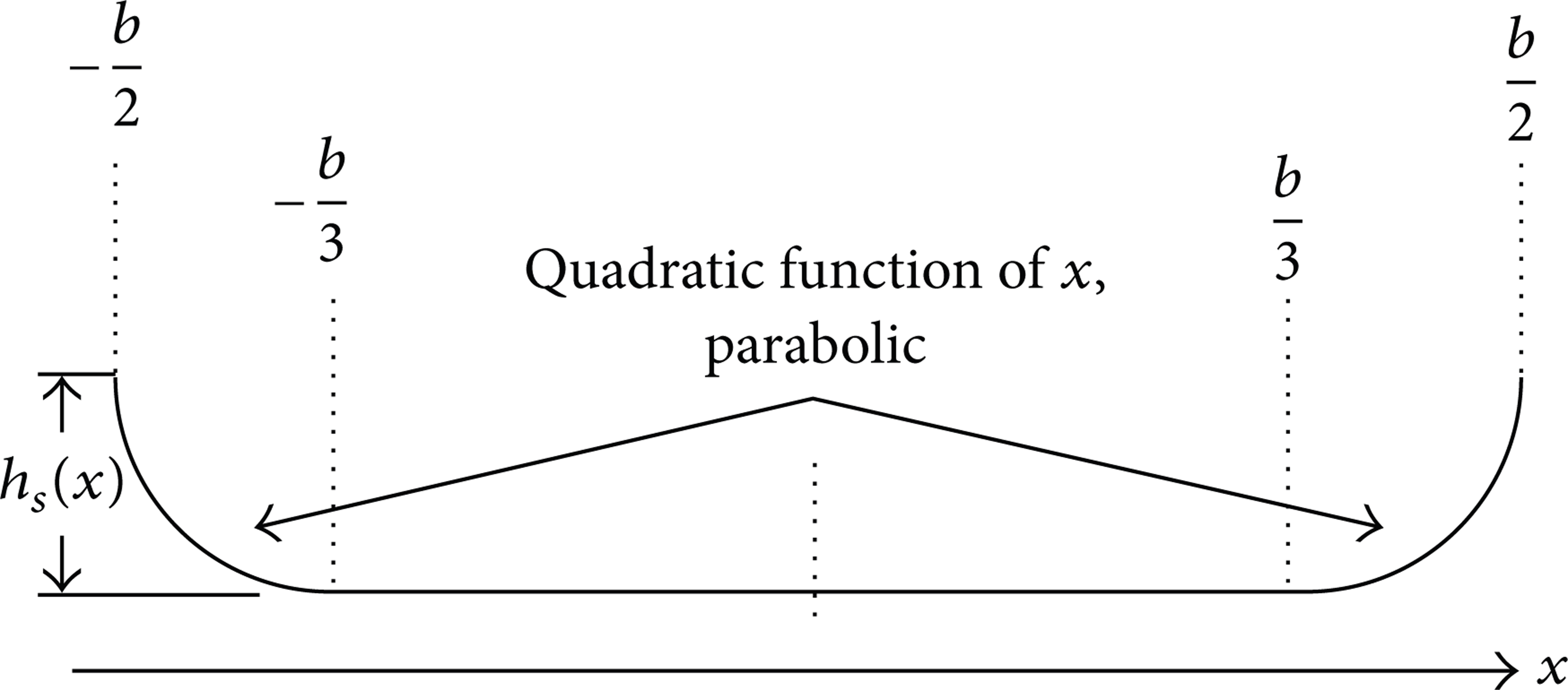
Detailed scheme of piston ring face profile.
Considering cylinder liner oil grooves, the gap between the ring face and the liner has been considered according to the following formulas.
(1) Elliptical Bottom Shape Groove. Consider

(2) Triangular Bottom Shape Groove. Consider

(3) Rectangular Bottom Shape Groove. Consider

The geometrical model of the grooves bottom shapes is presented in Figure 2. The overall cylinder liner has been divided into imaginary circumferential cells of equal dimensions. Each cell has width of ζ (assumed to be 4 mm in this study) and contains one oil groove of width 2r p , and depth h p . According to the literature [23, 24], the groove area density (S p ) and the groove aspect ratio (e) are the two keys parameters for the surface texturing, and they could be defined as follows:


(a) Schematic drawing of PR-CL interface with elliptical bottom shape-oil grooves. (b) Triangle bottom shape. (c) Rectangle bottom shape.
3. Asperity Contact Model
Assuming that the surface roughness of the piston ring and cylinder bore to be isotropic, the asperity contact pressure can be expressed according to Greenwood and Tripp's model of asperity contact [19] as

where β is the radius of curvature of asperity peak, η the asperity density, and
4. Boundary Conditions
The convergent-divergent shape of the piston ring face profile gives the opportunity to rupture the oil film due to the cavitation [25, 26], which usually occurs in the outlet region. According to well-known Reynolds boundary condition, the rupture boundary condition can be expressed mathematically as

where the pressure in the gas cavities, Pcavity, is the saturation pressure of the dissolved gas which is generally assumed to be atmospheric pressure [27]. In case of continuous oil film at the exit there would be no cavitation. The exit boundary condition will be

where P T represent the pressure at the trailing edge.
A fully flooded inlet condition is assumed in this study. Therefore, the inlet boundary condition at the leading edge of the ring is
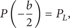
where P L represent the pressure at the leading edge of the ring.
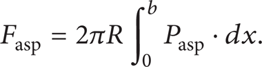
5. Frictional Force
Due to the reciprocating motion of the piston, the friction force between piston ring and cylinder liner in the mixed lubrication regime consists of two shearing forces: the lubricating oil film viscous force and the boundary friction due to asperity contact pressure. The total friction force can be expressed as

where ∅ f , ∅ fs , and ∅ fp are correction factors concerning the surface roughness and can be calculated according to Patir's model [18]. C f is the boundary friction coefficient.
6. Numerical Scheme
A new MATLAB code has been developed to numerically simulate the lubrication of the first compression piston ring of low speed 2-stroke marine diesel engine, considering multiscale, circumferential oil grooves on the cylinder liner. Grooves orientation has been designed to be perpendicular to the linear motion of the piston ring. The governing equations have been discretized using finite difference method and have been solved for each crank angle from 0–360 using a step size of half degree. Zero-degree crank angle is corresponding to BDC. The simulation starts from compression stroke and all calculations are for one complete cycle of engine. The solution starts from initial value of minimum oil film thickness (h m ). The scheme is repeated to get the minimum oil film thickness of top ring as a function of crank angle.
Since the piston ring lubrication condition is transient, this procedure is terminated when the forces balance is satisfied at each time step as

where

Pel and P g are the ring stiffness and back gas pressure forces, respectively. The relative positioning between piston ring and cylinder liner has been taken into consideration; that is, the oil film thickness along the ring face due to the groove effect is changed each crank angle, according to the exact position of piston ring with respect to cylinder liner oil grooves.
7. Results and Discussion
In the current algorithm, it has been assumed that the axial velocities of both of piston and the piston ring are the same. Table 1 indicates the engine parameters used to calculate the tribological behavior of the piston ring. However, piston ring dynamic input parameters have been exported to the model as numerical values, such as piston velocity and combustion chamber gas pressure, as depicted in Figure 3. Figure 4 illustrates the tribological behavior of piston ring, during one complete engine cycle, using nontextured cylinder liner. Nondimensional cyclic time-average values for each of hydrodynamic friction force, boundary friction force due to asperity contact pressure and total friction force, have been calculated for one complete engine cycle. Those calculations have been carried out for each groove shape of the three different bottom shapes: elliptical, triangular, and rectangular bottom shape. Table 2 shows the reference values, for each of the above parameters, for the case of engine with nontextured cylinder liner, to indicate the effect of oil grooves aspect ratio, area density, and bottom shape on those parameters.
Engine parameters used in calculation.

Reference values of piston ring tribological parameters (nontextured surface).

Piston ring dynamic input parameters. (a) Piston ring axial velocity. (b) Combustion chamber pressure.
Tribological behavior of piston ring using nontextured cylinder liner. (a) Asperity contact friction force during one complete engine cycle. (b) Hydrodynamic friction forces during one complete engine cycle. (c) Total friction forces during one complete engine cycle.
7.1. Hydrodynamic Friction Force
Generally, all ranges of oil grooves with high area density (S p > 25%) cause a noticeable increase in the hydrodynamic friction than that caused by the nontextured cylinder liner. As it is well known, the viscous friction is a representation of the shear stress in the layers of the lubricating oil film [28], due to the nonslip conditions between the moving surfaces. So the groove area density effect could be referred to the increase in oil flow due to the existence of oil grooves on the surface of the cylinder liner. And accordingly, the opportunity for the hydrodynamic lubrication to dominate the lubrication regime is increased. That may protect the engine form wear but, on the other side, it contributes to an increase in the hydrodynamic friction losses. As can be seen from Figure 5 the large area density (S p > 25%) of the elliptical bottom shape grooves increases viscous friction, for almost all aspect ratios. The viscous friction decreases with further decreasing in the densities of grooves area. From slopes of data curves in Figure 5(a) and their rapprochement trends in Figure 5(b), it could be deduced that the groove aspect ratio has a limited effect on the hydrodynamic friction force at small area densities. Figure 6 describes the viscous friction due to triangular bottom shape grooves. The same behavior as elliptical grooves could be noticed, but with slightly increase in viscous friction force at the small aspect ratios (e < 0.05). On the other hand, different behavior was experienced by the rectangular bottom shape-oil grooves. As can be noticed from Figure 7, the rectangular shape causes a dramatic increase in viscous friction force (up to 300%), and that increase is relatively limited for small area density. That behavior could be attributed to larger oil flow through the rectangular shape due to the geometry of the groove bottom, especially in the grooves with large area densities (S p > 10%).

Effect of using elliptical bottom shape-oil grooves on average hydrodynamic friction force. (a) Effect of aspect ratio. (b) Effect of area density.
Effect of using triangular bottom shape-oil grooves on average hydrodynamic friction force. (a) Effect of aspect ratio. (b) Effect of area density.

Effect of using rectangular bottom shape-oil grooves on average hydrodynamic friction force. (a) Effect of aspect ratio. (b) Effect of area density.
7.2. Boundary Friction Force
Boundary or asperity contact friction force is strongly correlated to the lubrication conditions. Figures 8 and 9 depict the time average nondimensional boundary friction force between piston ring and cylinder liner containing elliptical and triangular, respectively. For elliptical and triangular bottom shapes, the asperity contact friction force decreases with either increasing groove aspect ratio (e > 0.05) or decreasing groove area density (S p < 25% for elliptical groove, and S p = 25% for triangular groove). That could be attributed to the relative increase in hydrodynamic friction force caused by those groove dimension combinations, which points to the domination of the hydrodynamic lubrication regime. However, the increase in boundary friction in case of larger grooves area density may be referred to the decrease in hydrodynamic pressure due to the large grooves area, which may increase the oil flow but cannot sustain the piston ring working load. That leads to further metal-to-metal contact and hence increases the asperity contact force.

Effect of using elliptical bottom shape-oil grooves on average asperity contact friction force. (a) Effect of aspect ratio. (b) Effect of area density.
Effect of using triangular bottom shape-oil grooves on average asperity contact friction force. (a) Effect of aspect ratio. (b) Effect of area density.
Figure 10 depicts that the boundary friction force using rectangular bottom shape grooves is decreasing with increasing the groove area densities (S p > 25%). Generally, the rectangular shape grooves provide the minimum asperity contact friction, compared with the according dimensions of other groove shapes, and, hence, it offers the most opportunities of hydrodynamic lubrication. However, that type contributes negatively by increasing the hydrodynamic friction force, due to the high flow of oil through groove geometry. It could be further noticed from Figure 10(a) that the aspect ratio has a limited effect in boundary friction force.

Effect of using rectangular bottom shape-oil grooves on average asperity contact friction force. (a) Effect of aspect ratio. (b) Effect of area density.
7.3. Total Friction Force
The time average total friction force, over one complete engine cycle, is calculated and presented in Figures 11 through 13. As it would be expected from the correlative behavior of both hydrodynamic and boundary friction forces, Figure 11 depicts that the total friction forces due to elliptical bottom grooves decreases (up to about 15%) with either increasing of the groove aspect ratio, with optimum range of (0.075–0.15), or decreasing the area density (10–25%), which is analogous to literature results [8, 9]. Almost the same behavior experienced by triangular bottom shape grooves (Figure 12), but with larger total friction force at smaller aspect ratios and larger area density (S p > 25%).

Effect of using elliptical bottom shape-oil grooves on average total friction force. (a) Effect of aspect ratio. (b) Effect of area density.

Effect of using triangular bottom shape-oil grooves on average total friction force. (a) Effect of aspect ratio. (b) Effect of area density.
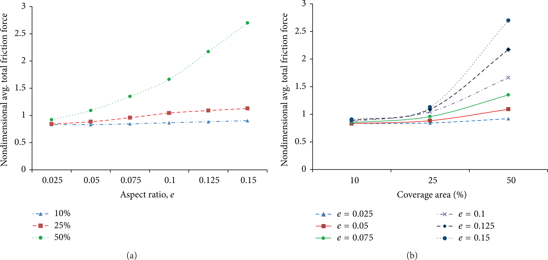
Effect of using rectangular bottom shape-oil grooves on average total friction force. (a) Effect of aspect ratio. (b) Effect of area density.
Figure 13 has been introduced in different vertical axes scale due to the larger values of total friction force experienced by using rectangular grooves. It can be deduced that total friction force increased largely by increasing the aspect ratio or grooves area density. However, the rectangular bottom grooves offer the same decrease in total friction force as elliptical and triangular bottom grooves at small aspect ratio (e < 0.05) for all range of area densities (S p = 10%–50%).
7.4. Hydrodynamic Pressure Distribution
Figure 14 illustrates the hydrodynamic pressure distribution along the piston ring face. The cavitation pressure is set to be the atmospheric pressure. It can be seen in Figures 14(a) and 14(b) that there is a limited pressure reduction before the edge of the elliptical and triangular bottom grooves, respectively. The pressure drop is more in case of triangular shaped due to the steeper converging zone of the triangular shape. The pressure drop is more noticeable in case of rectangular shape (Figure 14(c)) which is reasonable due to the sudden change of the rectangular gap. The geometric change and wedge divergence in the elliptical shape are much gentler. However, all shapes have pressure recovery mechanisms following the pressure reduction. Both elliptical and triangular shapes have a convergent wedge that acts as a microwedge which enhance the lubrication condition between moving surfaces, while the rectangular shape has a microstep bearing effect. The comparison between pressure plots indicated that the pressure recovery by the rectangular shape is more beneficial.

Hydrodynamic pressure distribution along the P.R face. (a) With elliptical bottom oil grooves. (b) With triangular bottom oil grooves. (c) With rectangular bottom oil grooves.
Such recovery can be referred to the edge-induced pressure enhancement which combines the effect of step bearing and is therefore much stronger. On the other hand, the bottom shape of the elliptical or triangular grooves gradually converges without the microstep bearing bottom effect. Based on the above discussion, the comparison reveals that the rectangular bottom shape has the strongest microbearing effect, and the cylinder liner with rectangular bottom grooves enhances the hydrodynamic lubrication by its microstep bearings. A very close conclusion has been presented by Nanbu et al. [21] on the microscale approach of surface texturing.
8. Conclusion
Based on the average flow theory, a numerical model has been developed to study the potential of use of cylinder bore surface texturing, in the form of circumferential different bottom shape-oil grooves, with different aspect ratios and area densities, to improve the tribological performance of piston ring-cylinder liner tribosystem. The results revealed that surface texturing on the cylinder liner caused a noticeable increase in the viscous friction force. However, limited increase is associated with small area densities (S p = 10–25%). Grooves aspect ratio has a negligible effect on viscous friction force. Grooves of higher depth to width ratio (e = 0.075–0.15) with lower coverage area (S p = 10%–25%) yielded the best results. These combinations provide a higher hydrodynamic pressure at the mixed lubrication regions and could act like small hydrodynamic bearings to protect the surfaces from direct contact. Elliptical and triangular bottom oil grooves decreased the total friction force to about 85% of the nontextured cylinder total friction. However the decrease in the boundary friction did not exceed 10%. On the other hand, although the rectangular bottom shape grooves increased the hydrodynamic friction force more than 300%, it decreased the asperity contact friction to below 65% of that with nontextured cylinder liner, which presents that type of bottom shape as the most effective texturing type. Furthermore, rectangular bottom oil grooves showed the strongest microbearing, and the cylinder liner with rectangular bottom grooves could enhance the hydrodynamic lubrication by its microstep bearings effect. The authors observe that this work needs to be extended with experimental study based on the aforementioned vision.
Conflict of Interests
The authors declare that there is no conflict of interests regarding the publication of this paper.