
Abstract
To recycle the vibration energy of vehicles over rough roads, a hydraulic-electricity energy regenerative suspension (HEERS) was designed in the present work, and simulations were performed with focus on its performance. On the basis of the system principle, the mathematical model of hydraulic-electrical energy regenerative absorber (HEERA) and two degrees of freedom (DOF) suspension dynamic model were constructed. Using the model of HEERA, simulations on force-displacement and force-velocity characteristics were performed with a 1.67 Hz frequency and a sinusoidal input adopted. And then in combination with HEERA model and two DOF suspension models, simulations on the performance of HEERS also were carried out. Finally, the influences of charging pressure and volume of the accumulator, hydraulic motor displacement, orifice area of check valve, and inner diameter of hydraulic pipelines on the performance of HEERA and HEERS were investigated in depth. The simulation results indicated that (i) the damping characteristic of HEERA was coincident with the damping characteristics of traditional absorber; (ii) the most remarkable influencing factor on the performance of HEERS was the hydraulic motor displacement, followed by orifice area of check valve, inner diameter of pipelines, and charging pressure of accumulator, while the effects of charging volume of accumulator were quite limited.
1. Introduction
The vibrations of vehicles on rough roads are usually absorbed by shock absorbers then transmitted into heat energy of oils and finally dissipated, with the purpose to improve the ride comfort of vehicles. The dissipated energy, if can be recycled to some extent, will improve the efficiency of utilization and reduce the fuel consumption significantly.
Exploratory efforts on the energy recovery of vehicle vibrations have been carried out by the domestic and foreign scholars. Okada and Harada have developed an electromagnetic energy regenerative system, with a linear motor adopted to recycle the energy of shock absorber [1]. In the studies performed by Jolly and Margolis, the recycling and release of vibration energy in suspension system have been achieved by an aerodynamic actuator [2]. Zuo and Zhang have evaluated the energy harvesting potential of the energy recovery suspension [3] and also developed the electromagnetic and rack-and-pinion energy regenerative absorbers, respectively [4]. Moreover, Li et al. have proved the feasibility of this rack-and-pinion type absorber by the bench and on-board tests [5]. An active suspension actuator composed by ball screws and a PM brushless DC motor have been proposed by Cao et al. [6, 7] whose comprehensive characteristics have been simulated and optimized by Huang et al. [8], Besides, Zhang et al. have carried out the on-board experiments on this kind of suspension [9]. Another pinion-and-rack type regenerative suspension combined with a DV servo motor has been developed by Yu et al.; moreover, its characteristics have been analyzed by simulations [10, 11]. Wang et al.have proposed a pin roller type regenerative absorber and performed the related matching calculations on its key components [12]. The device which transformed vibration energy into hydraulic energy has been proposed by Chen et al., and the results from simulations and experiments indicated that it could lead to an improvement of ride comfort and a reduction of fuel costs as well [13, 14]. Gysen et al. have performed intensive studies on a linear motor regenerative absorber, with a principle prototype system produced for on-board experiments [15–17]. In addition, a hydraulic electromagnetic shock absorber (HESA) has been studied by Fang et al., in which oils in the absorber cylinder were derived from a hydraulic rectifier bridge, flowed towards one direction and finally drove the hydraulic motor generator. Unfortunately, some differences of damping characteristics existed between this HESA and traditional absorbers; specifically, the damping force in the compression stroke exceeded it in the extension stroke. All of these made the HESA difficult to match the traditional suspensions, and thus further improvements were needed [18, 19].
In a conclusion, favorable damping characteristics are required principally in designing energy regenerative suspension, and then further studies on energy regenerative characteristics are meaningful. In the present work, the damping characteristics of HEERA, the performance, and the related influencing factors of HEERS were illustrated in detail.
2. Principle of HEERS
Figure 1 displays the principle of HEERS, from which we can find that HEERA is the key component composed by the hydraulic cylinder, check valves, the accumulator, the hydraulic motor, the generator, and hydraulic pipelines.

Schematic diagram of the HEERS A, B, and C node in hydraulic pipeline (showed as black dot).
As shown in Figure 1, during the compression stroke, the oils in the absorber cylinder were driven upwards by the piston. When passing through node C, the fuels flowed to check valve 2 due to the fact that check valve 1 was closed, while valve 2 was open. Passing through node A, most of fuels would flow into the inferior section of cylinder, since higher pressure existed in the oil pipelines located at the right side of node A during the extension stroke, and lower pressure existed in the inferior section of cylinder meanwhile. Due to the contraction of the rod cavity, the oils were prevented from accessing to the inferior cylinder and finally flowed towards the accumulator through node B.
During the extension stroke, the oil in absorber cylinder was driven by the piston towards the inferior section of cylinder and flowed to the right side when passing through node A, since valve 2 was closed. When passing through node B, the oils would flow into the hydraulic motor gradually, on account of the charging of accumulator during the compression stroke and then the generator worked with the hydraulic motor. Finally, the oil flowing through the hydraulic motor would enter the upper section of cylinder through valve 1.
It should be noted that in the abovementioned scheme designed for the absorber, the recovery pipelines were not functionalized during the compression stroke, while energy recycling merely occurred during the extension stroke. The design could make the damping force in the extension stroke exceeded that in the compression stroke. Consequently, the designed absorber would be closer to the traditional vehicular absorbers in the aspects of force-displacement and force velocity characteristics.
3. Mathematical Modeling of HEERS
To further analyze the performance of HEERS, corresponding mathematical models were established in accordance with the system principle diagram.
3.1. Mathematical Modeling of HEERA
In the present work, only taking the variation between the initial and final states in charging into account, mathematical models on the HEERA were constructed, with system leakage, gas volume, and transient behavior of pressure in the accumulator neglected.
3.1.1. Damping Force in the Compression Stroke
As stated above, with the fiction force between the piston and cylinder wall ignored, the damping force in the compression stroke can be described as

where p h and p l are the pressures in upper and inferior sections of cylinder and S h and S l are the surface area and ring area of the piston, respectively. As shown in Figure 1, the oil flowed from the upper towards the inferior section of cylinder through valve 2, which partially flowed into the accumulator because of the shrunken volume by the piston rod in inferior cylinder. In the compression stroke, pressure differences arose in check valve 2, accumulator, linear loss, and local loss in the hydraulic circuit.
The pressure difference when the oil passed through valve 2 can be calculated by the orifice compensated formula:

where ρ represents the density of oil, Q2 is the flow of oil passed through valve 2, c d denotes the flow coefficient, and S2 is the equivalent area of orifice in valve 2.
The linear friction loss in hydraulic circuit during the compression stroke can be expressed as

where u v is the motion viscosity of oil, l c is the length of hydraulic pipelines in the compression stroke, v c is the oil velocity in hydraulic pipeline during the compression stroke, and r c is the radius of hydraulic pipelines.
The local friction loss in hydraulic circuit during the compression stroke can be described as

where ε is the coefficient of local pressure and can be selected according to the specific layout of hydraulic circuit and v jc is the velocity of oil flues when passing through the local pressure loss area.
As described above, the primary role of accumulator was the absorption of redundant oils induced by the contraction of rod cylinder. Consequently, charging of accumulator occurred during the compression stroke. Taking the initial and final states of charging into account, without any considerations on the middle course, the pressure of accumulator in the compression stroke can be calculated according to Boyle's law:

where V0 is the initial volume of airbag, p0 is the initial charging pressure of the container, l(t) represents the relationship between the displacement and time of the piston, that is, l(t) = lmaxsin(2πft) when the input is sinusoidal wave, where lmax denotes the maximum distance of piston, and n0 is the gas polytrophic index.
Accordingly, the equation of pressure equilibrium in the circuit during the compression stroke can be expressed as

At the end of the compression stroke, relative balance could be maintained as gas pressure in accumulator which was equivalent to the pressure at the inferior section of hydraulic cylinder; that is, p h = pacc. Moreover, the flow of oil fuels in the compression stroke was assumed to be constant, since the volumetric difference between the upper and inferior chamber was negligible, and therefore the liquid stream towards the accumulator was invariable. The quantity of flow in the compression stroke can be described as

Taking (2)–(7) into (1), we can calculate the damping force of HEERA in the compression stroke as follows:

3.1.2. Damping Force in the Extension Stroke
The pressure difference between the inlet and outlet of check valve 1, local and linear pressure losses of HEERA in the extension stroke presented similar variations as those in the compression stroke; however, the region induced by local pressure loss in the extension stroke exceeded it in the compression stroke, which could be calculated by the practical layouts and is unnecessary to be discussed elaborately in the present work.
The oils flowed into the hydraulic motor and drove it worked. The output torque then produced electricity, which presents a relationship with the rotation rate of hydraulic motor as

where n, Q m , q, η v , T, and η m denote the rotation speed, flow, displacement, volumetric efficiency, output torque, and mechanical efficiency of the hydraulic motor, respectively, and Δp denotes the pressure difference between the inlet and outlet of hydraulic motor.
The motor was driven directly by the output torque of hydraulic motor; that is, the input torque of motor equaled the output torque of hydraulic motor, and therefore the formula of generator voltage with the moment of force can be expressed as

where U
e
is the induced electromotive force, k
v
is the coefficient of back electromotive force constant, w,J,
With the rotary inertia of generator rotor ignored, the pressure difference between the inlet and outlet of hydraulic motor can be calculated by

The equation of pressure equilibrium in the circuit during the extension stroke can be described as

where Δp1 is the pressure difference between the inlet and outlet of check valve 2, and Δp r and Δp jr are the linear and local pressure losses in the circuit during the extension stroke, respectively.
The damping force of HEERA in the extension stroke can be derived from (1)–(5) together with (7), (11), and (12):

where ε i denotes the corresponding local pressure coefficient of local pressure loss area generated in the extension stroke.
3.2. The Model of HEERS
The dynamic equations of HEERS can be derived in accordance with Newton's second law
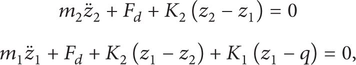
where the damping force F d provided by HEERA can be determined by (8) and (13).
4. Simulations on HEERA
4.1. Simulations on the External Characteristics of HEERA
Simulations were performed on the mathematical models of damping force in HEERA, by means of MATLAB, and the input of sinusoidal signal was adopted as follows:
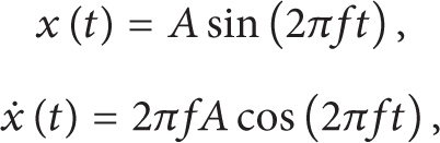
where x(t) is the displacement of piston,
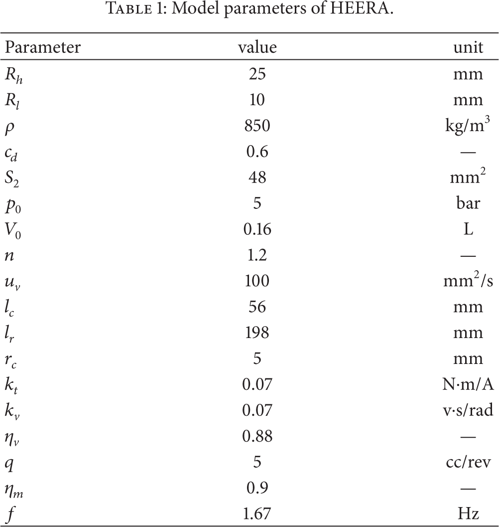
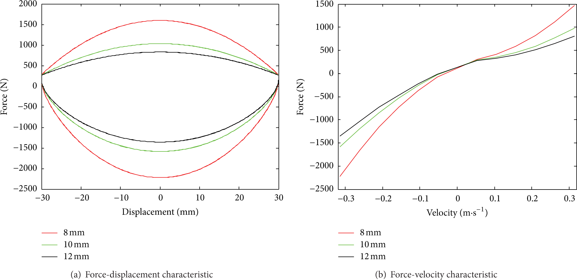
Simulations on the damping force of HEERA were carried out at the frequency of 1.67 Hz, and the stroke was set as 5 mm, 10 mm, 15 mm, 20 mm, 25 mm, and 30 mm, respectively, with the parameters employed in the simulations listed in Table 1. Figures 2 and 3 display the force-displacement and force-velocity characteristics of the HEERA calculated from simulations, in which the positive and negative values denote the damping force in the compression and extension strokes, respectively.
Model parameters of HEERA.

Simulation result of indicator diagram of HEERA.

Simulation result of speed characteristic of HEERA.
4.2. Influences of the Parameters of HEERA on the External Characteristics
According to the derived mathematical models of damping force in HEERA, the influencing parameters on the damping force included charging volume and pressure of accumulator, displacement of hydraulic motor, orifice area of check valve, inner diameter of hydraulic pipelines and, and so forth. With the variations of parameters described above, the influences on system performance were studied, as the frequency was 1.67 Hz and the stroke of piston was 30 mm.
As described in Figure 4, the damping force of HEERA during the compression stroke increased with the rise of charging pressure in accumulator, while decreased during the extension stroke. It can be concluded from Figure 5 that the damping force of HEERA reduced during the compression stroke with the inflation of charging volume in the accumulator, while it remained invariable during the extension stroke. As also shown in Figure 6, only the damping force during the extension stroke was susceptible to hydraulic motor displacement, which presented a reduction with the increase of motor displacement. In Figures 7 and 8, as the orifice area of valve and inner diameter of hydraulic pipelines increased, the damping force of HEERA decreased both in compression and extension strokes.

Influences of different accumulator initial charging pressure.

Influences of different accumulator initial charging volume.

Influences of different hydraulic motor displacement.

Influences of different check valve orifice area.
Influences of different hydraulic pipeline inner diameter.
Since the input frequency was fixed to be 1.67 Hz in the simulations, the velocity of the piston would increase correspondingly with the increase of piston displacement. As expected, the velocity characteristic curves would present identical tendency with the external characteristic curves and, therefore, would not be discussed in detail in the present work.
5. Simulations on HEERS
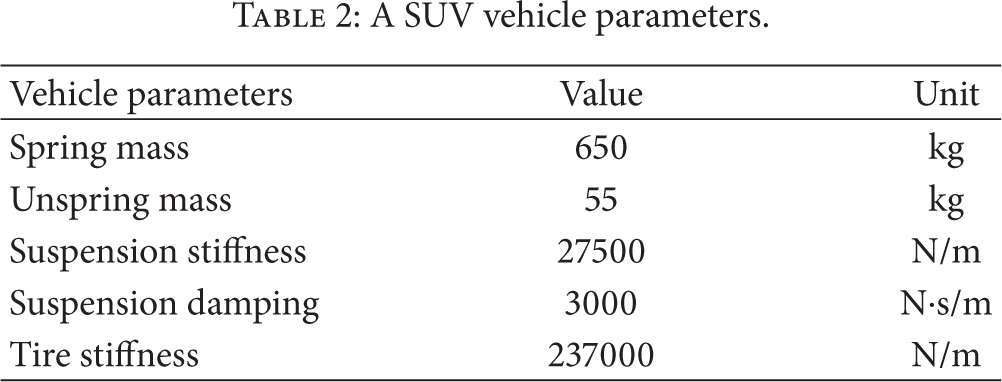
In the simulations, the vehicle parameters were set as the technical parameters of a SUV, the velocity was chosen as 40 km/h, and the road condition was selected as B-class road. The performances were evaluated in terms of sprung mass acceleration, suspension stroke, and the displacement of vehicle tire. Table 2 lists the technical parameters of the adopted SUV in the present work.
A SUV vehicle parameters.
The road models were constructed with the white-noise filtered method, by which the simulated pavement displacement can be obtained from the transformation of white Gaussian noise with a zero mean:

where q is the pavement displacement, f0 and n0 are the lower cut-off frequency and spatial frequency, respectively, G q (n0) is the density of pavement power spectra at the spatial frequency n0, u is vehicle speed, and w t is the Gaussian noise with a zero mean.
The HEERS model was developed with the use of MATLAB/Simulink toolbox, and the obtained situational results were compared with the results from the original SVU vehicles, as shown in Figures 9, 10, and 11. It can be easily found that the performance indexes of the SUV suspension equipped with HEERS were basically at the analogous level compared with the original SUV implying no significant changes on the suspension performances when modified by HEERS.

Comparison diagram of spring mass acceleration.

Comparison diagram of suspension dynamic deflection.

Comparison diagram of tire dynamic deflection.
Additionally, the effects of the variations of parameters including charging pressure and volume of accumulator, hydraulic motor displacement, orifice area of valve, inner diameter of hydraulic pipelines, on the performance of HEERS, were discussed. Aiming at presenting the variation tendencies of the suspension indexes with the related parameters more clearly, all the parameters were normalized to their initial values firstly, and the normalizations were also carried out after relevant RMS calculations. The curves after normalization could illustrate the variation tendencies of suspension indexes with the unit influencing factors, as displayed in Figures 12, 13, 14, 15, and 16.
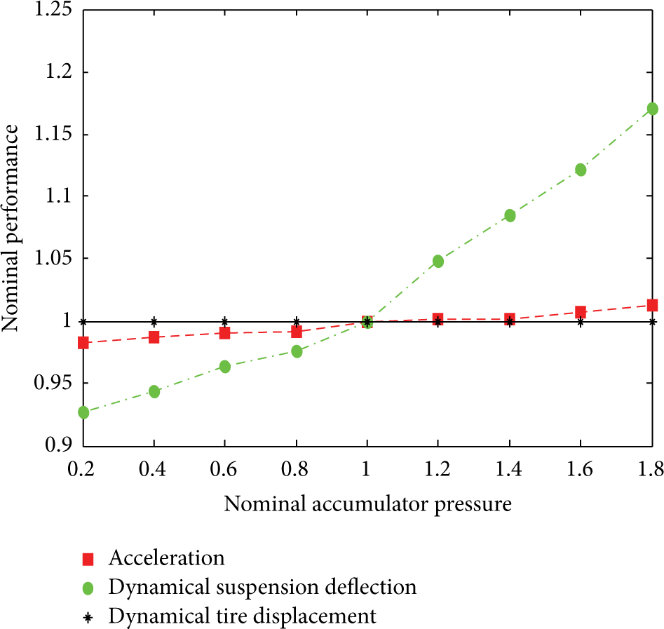
Effects of accumulator pressure.

Effects of accumulator volume.

Effects of hydraulic motor flow displacement.

Effects of check valve orifice area.

Effects of hydraulic pipeline inner diameter.
The major conclusions from the simulation results are outlined as follows: (i) the root-mean-square (RMS) value of vehicle acceleration increased with the rise of the pressure of accumulator, hydraulic motor displacement, orifice area of check valve, and inner diameter of hydraulic pipelines; however, RMS value of acceleration decreased with the expansion of accumulator charging volume; (ii) the RMS value of suspension dynamical displacement was almost unchanged with the variation of accumulator charging volume while being presented an obvious increase with increasing pressure of accumulator, hydraulic motor displacement, orifice area of valve, and inner diameter of hydraulic pipes; (iii) the displacement of vehicle tire was not affected evidently by the changes of accumulator charging volume and pressure; while the RMS value increased with the increase of hydraulic motor displacement, orifice area of check valve, and inner diameter of hydraulic pipelines; however, RMS of displacement turned to be changeless when the orifice area and inner diameter increased to certain values.
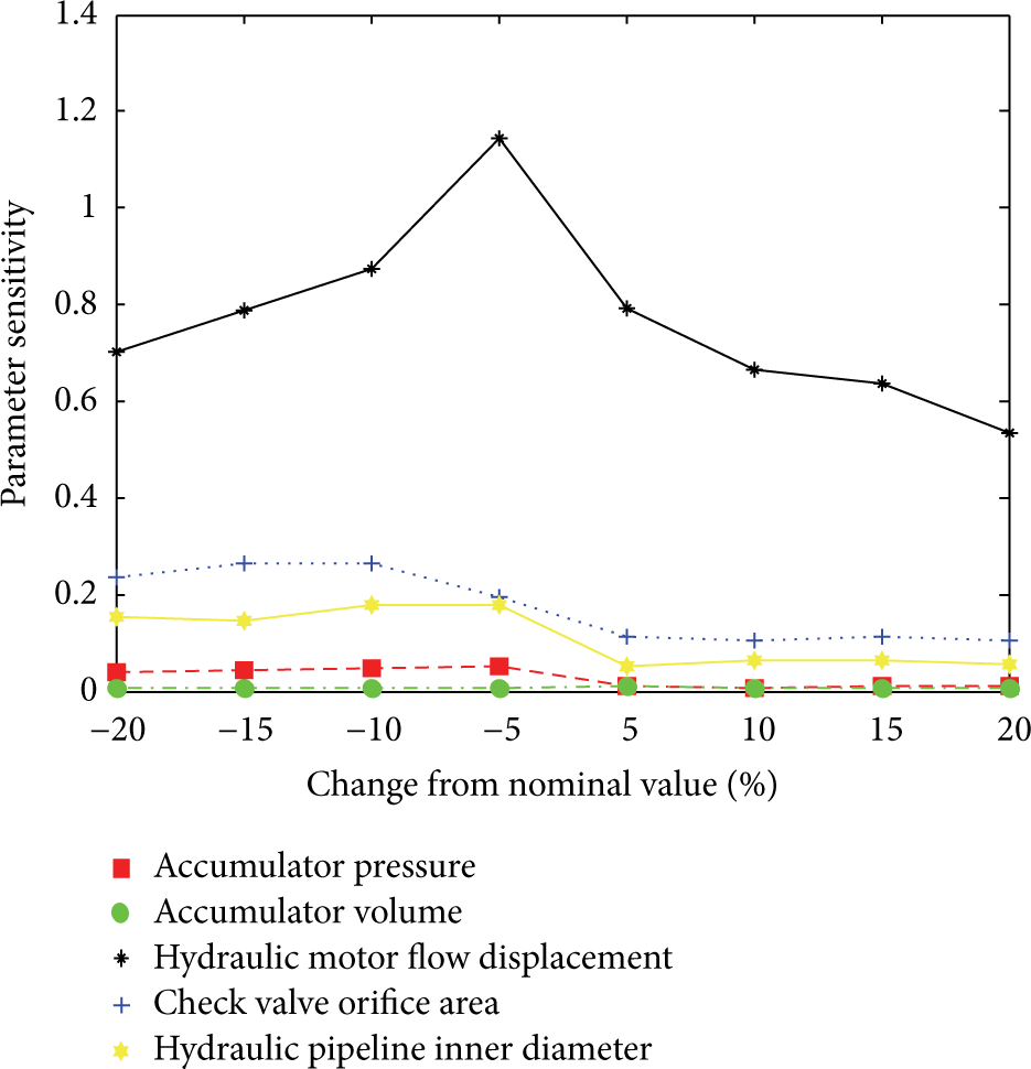
Moreover, with the purpose to investigate the effects of the parameters of HEERA on suspension performance, the sensitivities of suspension performance indexes to the parametric variations of HEERA were detected using one parametric variation method with the observed parameters including charging pressure of accumulator, charging volume of accumulator, displacement of hydraulic motor, orifice area of the check valve, and inner diameter of hydraulic pipelines. At each measurement, the selected parameter was increased by 5% of the initial value, while other parameters kept invariable. Then, the variations of the root-mean-square (RMS) values of vehicle acceleration, suspension dynamic displacement, and wheel dynamic displacement with the selected parameter were investigated. The sensitivity can be defined as

where s is the sensitivity of index to the selected parameters, Δy is the variation of index, Δx is the variation of the selected parameter, x0 is the initial value of the parameters, and y0 is the initial value corresponding to the situation when x = x0. The larger the sensitivity value, the more significant the effects of parameter on the evaluation of suspension performance. Figures 17–19 display the sensitivities of HEERS performance to various parameters.
Sensitivity of vehicle body acceleration.

Sensitivity of dynamical suspension deflection.

Sensitivity of dynamical tire displacement.
From Figures 17 to 19, it can be concluded that (i) in terms of the effects on vehicle acceleration, the influencing parameters with the sensitivity ranked in a descending order were the displacement of hydraulic motor, orifice area of check valve, inner diameter of hydraulic pipelines, charging pressure of accumulator, and charging volume of accumulator; (ii) in terms of the effects on suspension dynamical displacement, during the period of negative variation, the displacement of hydraulic motor was of most significance, the charging pressure of the accumulator, orifice area of check valve, and inner diameter of hydraulic pipelines were all ranked the second place, and the charging volume of accumulator presented no obvious effects; during the active variation period, the effect of hydraulic motor displacement ranked the first, charging pressure of accumulator followed, and the effects of others parameters ranked the third, while the effects of charging volume could be ignored; (iii) in terms of the effects on dynamic displacement of tire, during the negative period, the displacement of the hydraulic motor was posed as the most significant effect, the orifice area of check valve and inner diameter of hydraulic pipelines ranked second and third, respectively, and the parameters of the accumulator did not make any sense; during the active period, only the displacement of hydraulic motor made senses, while others could be ignored.
Conclusively, to give a comprehensive analysis on the overall tendency in Figures 17–19, it can be obtained that (apart from the charging pressure of the accumulator in active variation of the Figure 18) in accordance with the influencing index of HEERS, the parameters ranked in a descend order according to their effects were the displacement of hydraulic motor, orifice area of check valve, inner diameter of hydraulic pipelines, and charging pressure of accumulator. Nevertheless, the charging volume cannot make any sense to the performances of the HEERS.
6. Conclusions
In the present work, a design scheme of HEERS was introduced, and the mathematical models of HEERA were constructed in the light of system principle. Moreover, simulations on the damping characteristic were performed, in which the influencing factors of damping force were investigated by the variations of the parameters of various main components in absorber. With the reference to two DOF suspension models, the performance and influencing factors of HEERS were studied, and the results are listed as follows.
The characteristics curves of force-displacement and force-velocity were plotted with the simulation results of the damping force in HEERA, which indicated that, similar to the external characteristics in traditional absorber, the damping force in the compression stroke was smaller than that in the expansion stroke.
The influences of charging pressure and volume of accumulator, displacement of hydraulic motor, orifice area of check valve, and inner diameter of hydraulic pipelines on vehicle body acceleration, suspension dynamical displacement, and tire dynamical displacement were investigated, and the results indicated that the most remarkable factor in the performance of HEERS was the displacement of motor, followed by orifice area of check valve, inner diameter of pipeline, and charging pressure of accumulator. The effect of charging volume of accumulator on the performance of suspension, however, seemed to be very limited.
Conflict of Interests
The authors declare that there is no conflict of interests regarding the publication of this paper.
Footnotes
Acknowledgments
The authors gratefully acknowledge the National Natural Science Foundation of China by 2011 (Project no. 51075312) and 2013 (Project no. 51305314), the Fundamental Research Funds for the Central Universities (WUT: 2013-IV-073, 2014-IV-036), and Wanxiang Group Corporation Technology Center.