
Abstract
An excellent oil-air lubrication system helps to improve rolling bearing's working conditions and thus extend its service life span. Flowing and heat dissipating characteristics of oil-air media inside bearing chamber are very complicated due to the fluid-solid thermal coupling. Effects of fluid-solid thermal coupling are neglected in all previous simulation efforts. A numerical model for simulating the flowing inside bearing chamber is developed here based on an analytical fluid-solid thermal coupling method under oil-air lubrication. The effects of the coupling of air-oil flowing and heat dissipating in bearing chamber are predicted. The simulation results indicate that the coupling is influential in the performances of the flowing in rolling bearing under oil-air lubrication. With consideration of the coupling, the turbulence intensity, the turbulent kinetic energy, and the temperature of the rollers are predicted to be lower because part of the heat is carried out by the flow due to the heat transfer. On the contrary, the turbulent dissipation rate gets higher when considering the coupling effects. It is also interesting that the coupling effects have little influence on the flow pressure and the velocity, which is manifested by a little higher predicted value when considering the coupling.
1. Introduction
Oil-air lubrication finds its wide applications in rolling mill machinery and equipment due to the merits of precise oil quantity control and high cooling efficiency. A very small quantity of oil can be delivered to the friction surface by means of compressed air flow and ensue accurate lower air pollution and power loss under oil-air lubrication conditions. The design of high performance oil-air lubrication system is the major concern for improving the service life of friction pair and the operating performance of the overall equipment. Those have attracted many scholars and design engineers' attention which can be found from existing literatures [1].
The air supplying design is a key factor which affects the temperature rise of the friction surface and air also is a necessary component in the active oil-air lubrication system. The delivering state of the air not only affects the microprocess of the formation of lubricant film on the friction surface but also affects the macro operating performance of the friction pair. Taking into account the complexity of oil-air supply, the existing investigations were mainly devoted to the macro working characteristics of the rolling bearing which were based on experimental studies under oil-air lubrication. Itoigawa et al. [2] examined the relationship between the rotating speeds of the ball and the oil supply rates through experiments on angular contact ball bearing lubricated by the oil-air lubrication system and summarized a relationship between a starvation factor in the ball-race contacts and the oil supply rate. Jeng and Gao [3] established equipment for measuring the fluctuation in the oil supply and studied the effects of the preload, oil quantity, air flow rate, and rotating speed on the bearing temperature rise by testing. Oil-air lubrication system was applied to an ultra-high-speed grinding spindle by Ramesh et al. [4], and researches on the lubricant film thickness and heat transfer phenomena were put forward through experiments. Yeo et al. [5] examined the performance of the oil-air lubrication of the ultra-high-speed grinding spindle and bearing system. Wu and Kung [6] investigated the performance of a high-speed spindle under different lubrication parameters and preloads. They concluded that oil volume-per-cycle, lubrication cycle, and air pressure are three most significant factors that affect the temperature rise in an oil-air lubricated spindle.
Chen et al. [7] offered many valuable fundamental researches on lubricating properties of oil-air two-phase flow in bearing chamber and heat exchange in the aero engine bearing chamber. National Natural Science Fund Committee [8] also carried out a research on air-liquid two-phase flow and lubrication characteristics in high-speed aero engine bearings. Jiang and Mao [9] developed an experiment setup to investigate the oil-air lubrication for the high-speed ball bearing and found the influence of the amount of oil, oil viscosity, oil-air pressure, oil-air temperature, and other factors on temperature rise. Wang [10] developed a testing rig to measure the temperature field of oil-air lubrication and study the lubricating effect of oil amount in the oil lubrication process. Chen et al. [11, 12] also carried out some investigations on the oil-air lubrication in the tension leveler and the experiments show that the bubbly liquid lubrication has good performance in high-speed spindle bearing. It can be clearly seen that the above-mentioned researches played positive roles in revealing the impact on the rolling bearing operating performance from oil-air flow in the bearing chamber.
Some progress also has been made in the numerical studies about the flow of oil-air inside the rolling bearing chamber. Chen [11] considered the dynamic flow of compressed air in the bearing chamber as a kind of flow which is between the two extreme dynamic flow processes. One refers to the flow from the nozzle directly to the gap between the two balls, and the other is the flow from the nozzle directly to the sides of the two balls. And then, the dynamic problem of oil-air flowing inside the bearing chamber was simplified into a static one. With the rapid development of computational fluid dynamics (CFD), the numerical simulation method has provided an effective tool to solve the problem of the flow field and to predict the performance [13–16]. Chen et al. [7] developed a numerical model for predicting the lubricant flow inside an aero engine bearing chamber, with film/droplet/air interactions taken into consideration.
Zhang [17] investigated the temperature field of the bearing chamber of annealing flat supporting roller by simplifying the bearing solid to thin wall without considering the thermal coupling of the fluid and solid. The method involved the heat transfer between fluid and the solid wall, which did not involve internal thermal conductivity of the solid wall and only the convective heat transfer coefficient of the wall was set. By using the flow field numerical simulation functions of FLUENT software, the authors [18] introduced an analytical method to simulate the air flowing in a bearing chamber with considering the effect of bearing's twirling.
In this study, a model based on the fluid and solid thermal coupling method is introduced to analyze air-oil flowing and heat dissipating in rolling bearing by calculating heat generating and transferring. By means of numerical simulation, the operation parameters of oil-air medium such as velocity field, pressure field, and turbulence inside the bearing chamber are investigated systematically. Conclusions are expected to give some useful references and basic support for the characteristics predicting of oil-air flow and heat dissipation inside rolling bearing chamber under active oil-air lubrication.
2. Calculation of Basic Parameters
2.1. Calculation of Friction Torque
Many analytical models have been established to calculate the friction torque of cylindrical rolling bearing. In addition to the use of mathematical method, the empirical formulas of the bearing friction torque were obtained through the experiments of various sizes of cylindrical rolling bearings by Harris and Kotzalas [19]. The formulas considered different factors such as load, speed, and lubrication. Calculated results from these formulas agreed well with the actual situation. Thus, it has been widely used in characteristics computing and simulation of rolling bearings.
Friction torque of cylindrical roller bearings mainly includes two aspects: one is due to the applied load torque and the other is due to the viscous friction of the lubricant. Torques can be calculated as follows.
The applied load torque can be described by the following equation [11]:

where f1 is a coefficient related to the bearing structure and the load, Fβ is the bearing load, and d m is average diameter of the bearing. Here, d m is defined as

where D is outer diameter of the bearing and d is inner diameter of the bearing.
The viscous friction of the lubricant for the normal speed bearings is represented by the following equations [11]:

where n is rotating speed of the inner ring, v0 is a kinematic viscosity of the lubricant at the working temperature, and f0 is a coefficient related to bearing's type and lubricating method.
Total frictional torque of the rolling bearing is due to the applied load torque and the viscous friction of the lubrication and can be defined as

where M is the total friction torque of the rolling bearing.
2.2. Calculation of the Heat
Power loss of the rolling bearing is the product of the total bearing friction torque and angular velocity of the bearing's inner ring [19]. Then, heat generation from bearing system can be defined as

where Q1 is the heat of bearing.
2.3. Viscosity of the Lubricant
Bearing's friction torque and heat production are closely related to the lubricant kinematic viscosity. Every kind of lubricant has its own viscosity-temperature relationships. At present, the relatively accurate viscosity-temperature relationship on petroleum products is described by VALLES equation [20]:

where v is kinematic viscosity, T is absolute temperature, and a, b, and c are parameters associated with the composition of the lubricant. After several experimental statistic analyses, a is selected as 0.6.
The viscosity of HM68 antiwear hydraulic oil at 40°C is 68cSt, while the viscosity is 8.6cSt at 100°C. The values of b and c can be obtained according to VALLES equation. Then, the kinematic viscosity of lubricants can be solved at different temperatures.
2.4. Calculation of Heat Transfer Coefficient
It is very difficult to examine the convection heat transfer in bearing chamber because of bearing's complex structure. Simplified method must be adopted here in order to investigate the flowing of oil-air.
In order to avoid the oil agitation in bearing chamber, the supplying of oil is only able to form the required film thickness. So, the absorbed heat by the lubricating oil can be ignored in the heat transfer analysis. It assumes that the heat exchange occurs only between the bearing and the air in the chamber.
The area (Sax) of the axial flow of compressed air through inner and outer raceway of the bearing can be defined as
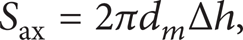
where Δh is the clearance between the inner and outer rings.
Synthesis velocity of compressed air in the bearing chamber can be calculated from the axial velocity and the radial velocity:
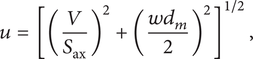
where u is the average speed of compressed air, V is the volume of air flow in the bearing, and w is angular velocity of the axis.
So, forced convection heat transfer coefficient between the bearing and the compressed air can be expressed by the following empirical formula [21, 22]:

where c0, c1, and c2 are empirical constants, which are 9.7, 5.33, and 0.8, respectively.
Natural convection heat transfer coefficient α1 [23] between the surface of bearing seat and the air can be expressed as

where G r is GRAHAM AKIO criteria, which reflects the impact of the physical properties to the heat exchanging; where P r is PRANDTL criteria, which reflects the strength of the fluid natural heat exchanging. K f is thermal conductivity coefficient of the lubricant and D h is outer diameter of the bearing seat.
The convection heat transfer coefficient between the shaft side face and compressed air can be calculated with (9).
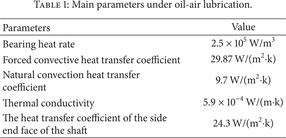
The main parameters of roller bearing under oil-air lubrication are calculated by the above equations and shown in Table 1.
Main parameters under oil-air lubrication.
3. Modeling and Parameter Setting
3.1. Calculation Model and Computational Grid
In order to improve the efficiency of modeling, meshing, and iterative calculation, the following simplifications and assumptions are made:
self-rotation moving of rollers is ignored;
the cage of rolling bearing is ignored in order to simplify the divided grid;
the contact part between the shaft and the bearing is selected for the shaft modeling;
the connection structures and parts such as holes and bolts are ignored in the modeling of bearing seat.
A schematic view of the roller bearing under oil-air lubrication is shown in Figure 1. Two circumferential sections X1 and X2 are selected for investigation which are 19 mm and 25 mm away from the inlet end face, respectively.
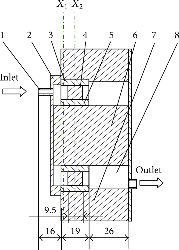
A schematic view of the roller bearing (mm). 1: nozzle, 2: bearing end cap, 3: bearing out ring, 4: bearing roller, 5: bearing inner ring, 6: shaft, 7: bearing seat, and 8: internal flow field area.
The block meshing is used for the flow field and refined mesh grids are applied in special area that needs to be investigated sophisticatedly. The tetrahedral element is used for other regions. The entire device is divided into more than 106 elements. Meshing model of the flow field in roller bearing is shown in Figure 2.
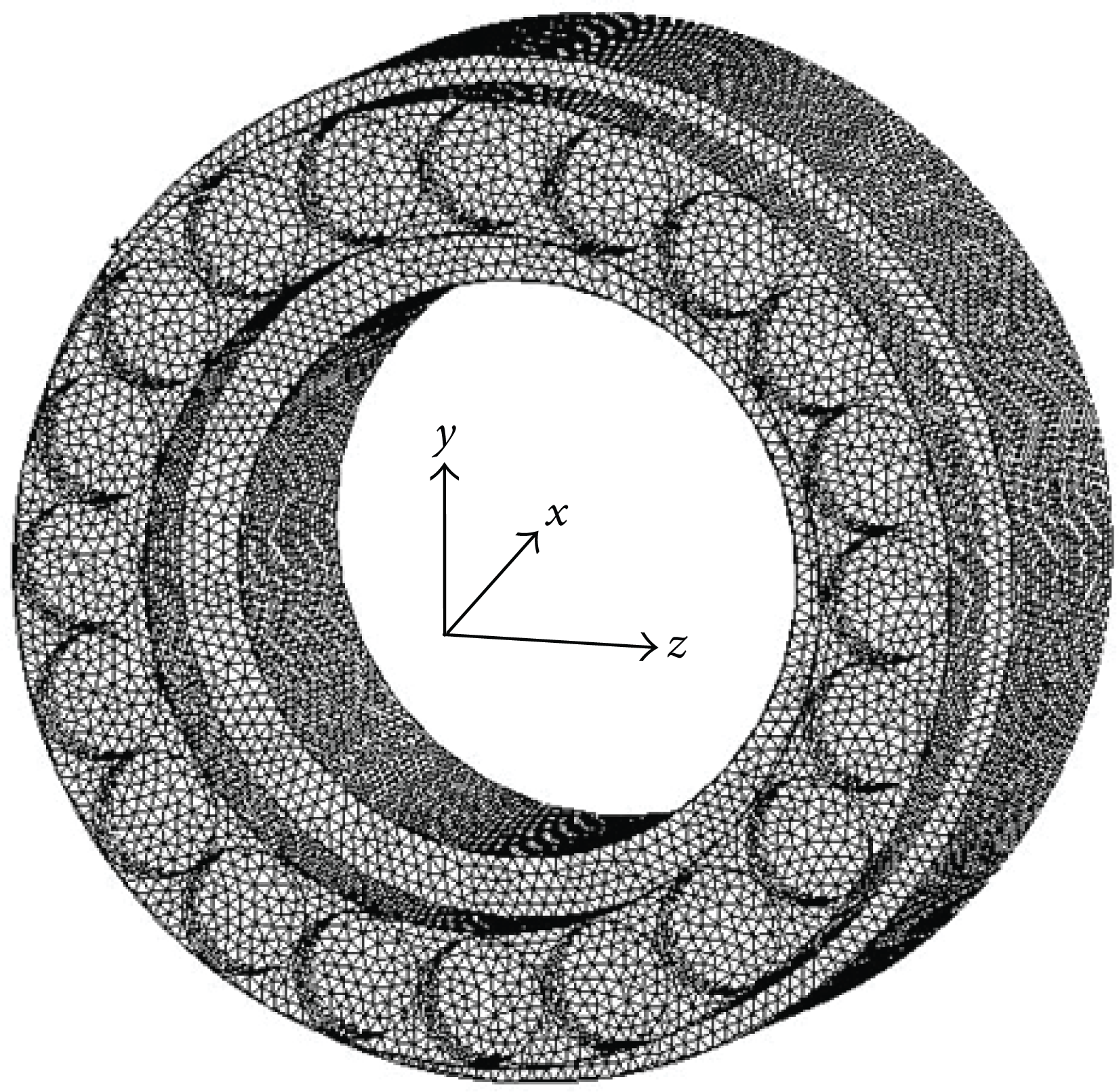
Meshing model of the flow field.
3.2. Setting of Physical Parameter
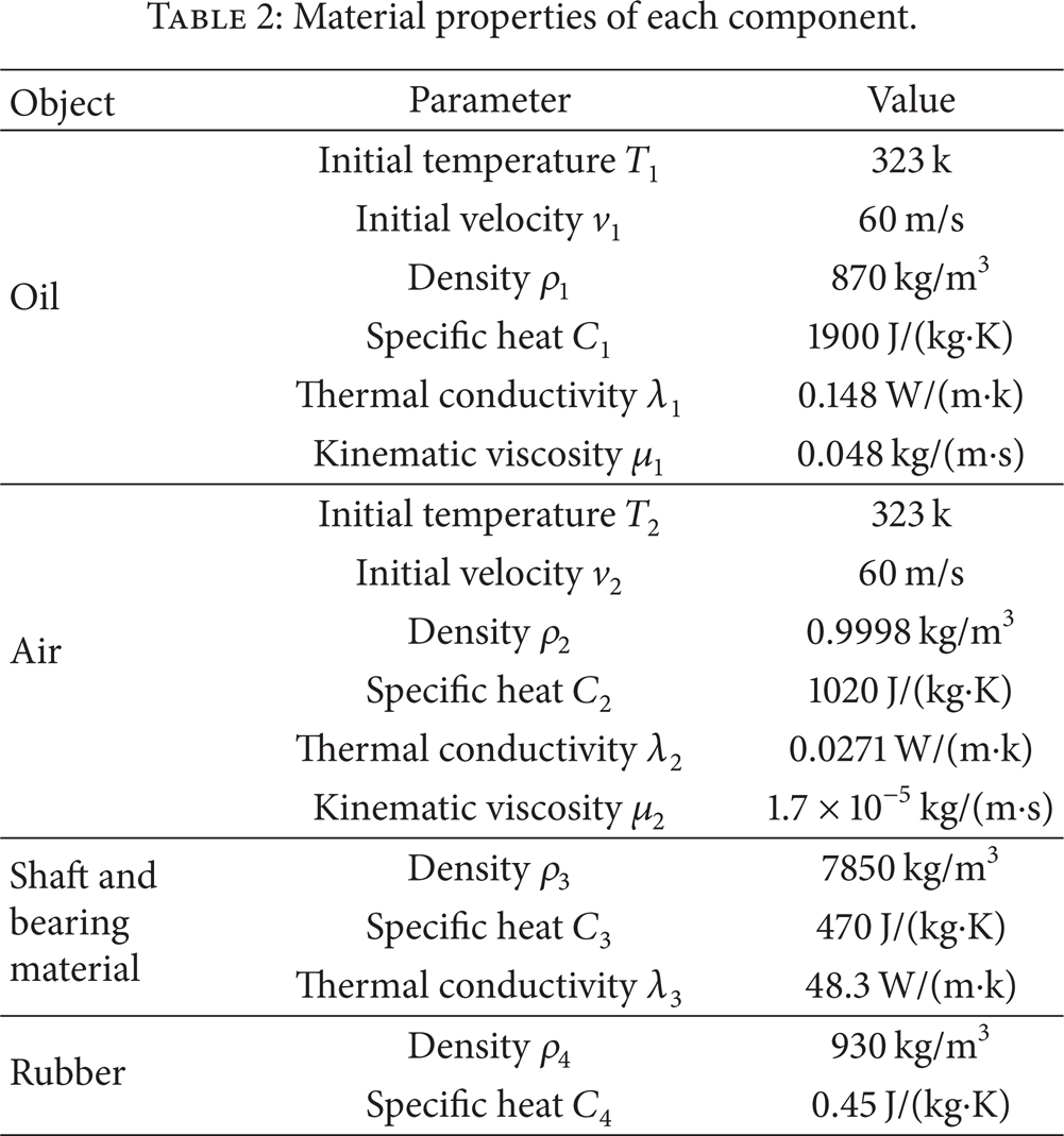
Physical properties parameters such as density, thermal conductivity, and specific heat capacity of the fluid and the solid can be set in FLUENT software. HM68 lubricant is adopted here and the physical parameter of air is set as ideal incompressible gas. The material of shaft and the bearing are usual steel, while the bearing seat material is cast iron. There is little difference between steel's linear expansion coefficient and that of cast. The bearing inner ring and the shaft and the outer ring and bearing are considered as a whole part [24], respectively, which are set as the static physical parameters of the 45 steel. The material of nozzle is rubber. The material properties parameters of each component are shown in Table 2.
Material properties of each component.
3.3. Setting of the Boundary Condition
Considering the influence from heat transfer, the parameters of rate of heat and convection heat transfer coefficient are calculated and set in FLUENT. Rollers are set as heat source. Contacting surface between the internal fluid and solid parts is set as default coupling-surface, and the convection heat transfer is calculated automatically. The convection heat transfer coefficient between the bearing seat and the air is set according to the previous calculated results.
A mixed model of oil-air two-phase flow is adopted in this study. The oil is set as the first phase, while the compressed air is set as the second phase. Velocity inlet boundary is set at nozzle and velocity is selected as 60 m/s. Pressure outlet boundary is set at the outlet and pressure is set as a standard atmospheric pressure. The rollers and the bearing inner ring are set as rotating wall, whose rotation speed is equal to the shaft. The roller's self-rotation speed is ignored and revolution speed is set as 1500 r/min. And the bearing is loaded with 1.5 kN in rotation. The rest is set as the wall boundary.
Finite volume method is introduced to discrete control equations here, and separate implicit solving method is adopted in the solving of the flow field model in rolling bearing chamber. The RNG k-∊ two-equation model is used in the process of computation. The wall of rolling bearing is set as no-slip boundary, and standard wall function is adopted in the near-wall region. In order to get a higher convergence precision, the pressure, speed, orderly viscosity coefficient, and turbulent energy are all set in second-order upwind format in differential format. And SIMPLEC algorithm is introduced to simulate the coupling of pressure and velocity.
4. Results and Discussions
4.1. Comparison of Velocity Field
The velocity vectors at circumferential sections X1 and X2 are shown in Figures 3 and 4. Colors of the arrows indicate the speed rates of the flow, while directions of the arrows show the directions of the flow. As shown in the figures, most of the oil-air flows in the clockwise direction which is consistent with the rotation direction of the shaft. It also can be seen from these figures that the direction of the flow is changing sharply near the entrance area due to the resistance from roller. The value and the direction of the flow are similar on the cross-section, whether we consider the influence from the fluid-solid thermal coupling or not. However, the value of velocity predicted with considering coupling is a little larger than that predicted with the other ones on both X1 and X2. The max-velocity and min-velocity on X1 are 0.4 m/s and 0.029 m/s, respectively. Meanwhile, they are 1.1 m/s and 0.108 m/s on X2, respectively.

Velocity vector on the X1 cross-section.

Velocity vector of the X2 cross-section.
The velocity of the flow in the axial direction is shown in Figure 5. The axial direction velocities in both cases are basically the same, whether we consider the influences from flow-solid thermal coupling or not. The value of velocity predicted by numerical simulation drops significantly near the area from 16 mm to 25 mm and becomes stabilized finally. The velocity is significantly decreased before entering the roller gap segment due to the resistance from roller's end face, while the velocity of oil-air has a small change when flowing through the bearing clearance.

Velocity of the flow in the axial direction.
4.2. Analysis of the Pressure Field
The shared axial section of the nozzle and the bearing is selected for studying emphatically and the predicted pressure contours of this section are shown in Figures 6(a) and 6(b). It can be found that the pressure of the flow degenerates gradually from the inlet to the outlet in both cases but keeps a positive pressure environment inside the bearing chamber. It is similar for overall pressure contours whether we consider the influence from the fluid-solid thermal coupling or not. However, the maximum pressure is a little higher than that without considering coupling effects. The difference of these maximum pressures is only 7 kPa, which is far lower than the pressure value on the whole section. So it can be found that coupling effect has little influence on the predicted value of the flow pressure.

Pressure contour of the axial section (z = 0 mm).
4.3. Turbulence Characteristics of the Flow Field
Influence from the distributions of turbulence intensity, turbulent kinetic energy, and turbulent dissipation rate is essential to turbulence both macroscopically and microscopically. Micelle size of the flow is affected by those parameters remarkably. Comparing research is introduced here to study how fluid-solid thermal coupling will affect those factors.
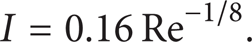
The turbulence intensity of the upper part of the axial section is shown in Figure 7. The nephogram of turbulence intensity in both cases is nearly the same. It can be found that the turbulence intensity in central location is greater than that near the wall in the right side portion of the figure. That is because the Reynolds number (Re) in central location is less than that near the wall due to the resistance from the roller, while the value of the turbulence intensity (I) is inversely proportional to the Reynolds number which can be explained by the flowing formula as

Turbulence intensity of the axial section (z = 0 mm).
It also can be judged from the figures that the predicted result of the turbulence intensity when considering the influence from the fluid-solid thermal coupling is a little lower than the other ones. With consideration of the coupling, the maximum and minimum of the turbulence intensity are 692 and 28.1, respectively. Meanwhile, the corresponding value is 748 and 28.5 in the other case, respectively. Temperature of the flow in the bearing chamber is higher when considering the influence from the coupling, and the corresponding Reynolds number is also higher. So, the turbulence intensity is lower than that predicted in the other case.
Turbulent kinetic energy provides an effective indication to evaluate turbulence's development or decline which is related to velocity and turbulence intensity of flow. The turbulent kinetic energy of the axial section near the nozzle is shown in Figure 8. It can be seen that the turbulence intensity has great impact on the turbulent kinetic energy and the distribution of turbulent kinetic energy is similar to the turbulence intensity. And it also can be found that the predicted results of the turbulent kinetic energy with considering the influence from the fluid-solid thermal coupling are lower than the other one.

Turbulent kinetic energy near the inlet (z = 0 mm).
Turbulent kinetic energy in the nozzle center is shown in Figure 9, which is in the distance from 0 mm to 10 mm from the end faces of the roller. It can be seen that the trend of the curve for turbulence intensity in both cases is basically the same. The maximum values of the turbulent kinetic energy all appear at the distance about 1 mm from the roller. However, the maximum of turbulent kinetic energy is lower when considering the influences from the fluid-solid thermal coupling. From 0 mm to 5 mm, the turbulent kinetic energies predicted in two cases all have an increase and then decrease to a relatively stable state. There is little difference from 5 mm to 10 mm in both cases and the turbulent kinetic energies are basically the same.

Turbulent kinetic energy in the nozzle center.
Turbulent dissipation rate refers to the rate of transforming the turbulent kinetic energy into the kinetic energy of thermal motion under molecular viscosity. Distributions of the turbulent dissipation rate of the axial section near the inlet are shown in Figure 10. The turbulent dissipation rate is up to 3.31 × 10⁶ m2/s3 when considering the influences from the fluid-solid thermal coupling, which is higher than that without considering the coupling. The intermolecular thermal motion becomes more intense when considering the heat transfer between the flow and solid under the effect of thermal coupling. And then the transforming rate will get a higher speed than the other case.
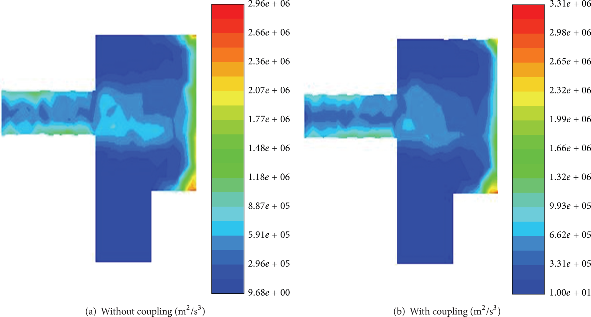
Turbulent dissipation rate near the inlet (z = 0 mm).
4.4. Temperature of the Rollers
In the case of considering the influence from the coupling, distribution of the end face temperature of the rollers is shown in Figure 11(a). It can be found that the maximum temperature appears in the area which is directly opposite the nozzle. A similar pattern is also achieved in the other case which is shown in Figure 11(b). However, the highest temperature of the roller is 327 K when considering the influence from the coupling, which is lower than the other one at 333 K. So it can confirm that the coupling has a great effect on the temperature field of the rollers predicted by simulation. The temperature of the rollers is lower when considering the coupling effect. It is because part of the heat is carried out by the flow when considering the heat transfer between the flow and the solid under the effect of heat coupling.
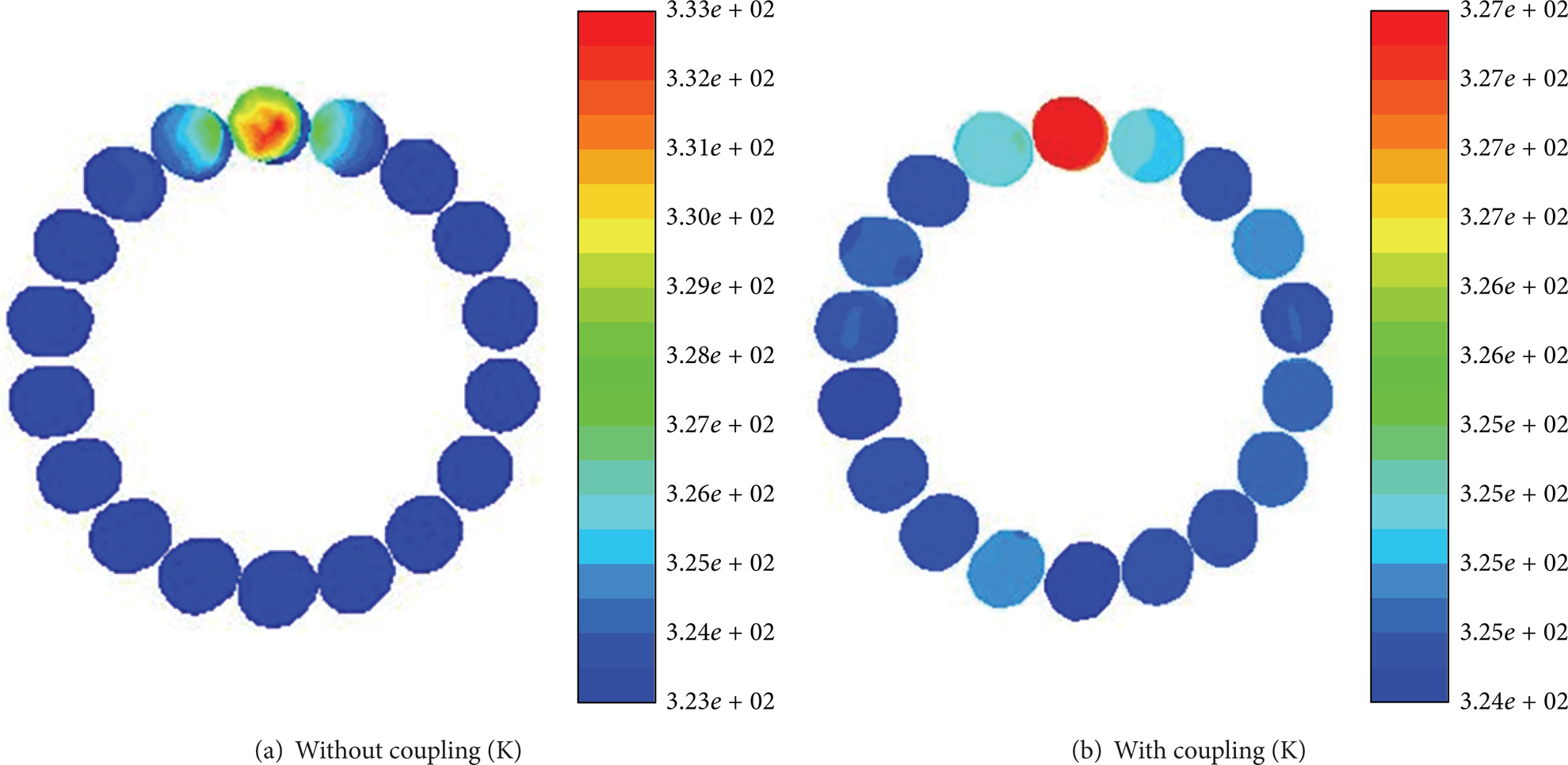
Temperature of the end face of the rollers.
The comparison of highest temperatures on each roller's end face in the circumferential direction is shown in Figure 12. It can be seen that the highest temperature of the roller's end face in the inlet is higher than that of the outlet whether we consider the fluid-solid thermal coupling or not. The reason lies in the fact that there is more oil-air impact on the rollers end face in the entrance. It also can be found that the values of the highest temperature predicted when considering the coupling are more uniform than that in the other case. The largest difference among the values predicted with considering the coupling is no more than 3 K at the inlet, while it is close to 10 K in the other case. Meanwhile, the corresponding value is 2 K and 5 K at the outlet, respectively.

Highest temperature on the end face of the rollers.
5. Conclusions
Effect of the fluid-solid thermal coupling cannot be neglected in the numerical simulation for predicting the performance of the flowing in rolling bearing under oil-air lubrication.
The velocity is significantly decreased before entering the roller gap segment due to the resistance from roller's end face, while the velocity of oil-air has a little change when flowing through the bearing clearance. The value of velocity predicted with consideration of the coupling is a little larger than the other one.
The coupling effect has little influence on the predicted value of the flow pressure. It is similar for overall pressure contours whether we consider the influence from the fluid-solid thermal coupling or not.
The turbulence intensity in central location is greater than that near the wall. When considering the coupling, both the predicted turbulence intensity and the turbulent kinetic energy are a little lower than the other ones. And the distribution of turbulent kinetic energy is similar to the turbulence intensity, while the turbulent dissipation rate with considering the coupling is higher than that without considering the coupling.
When considering the coupling effect, the temperature of the rollers is lower due to the fact that part of the heat is carried out by the flow under the effect of the heat transfer. The highest temperature of the roller's end face in the inlet is higher than that of the outlet whether we consider the coupling or not.
Conflict of Interests
The authors declare that there is no conflict of interests regarding the publication of this paper.
Footnotes
Acknowledgments
Financial support from Anhui Provincial Natural Science Foundation (Grant no. 10040606Q09), Anhui University Provincial Natural Science Research Project (Grant no. KJ2013Z019), and Zhejiang Sci-Tech University, the Province Key Laboratory of Fluid Transmission Technology (Grant no. ZSTUZSL2012A007), is hereby acknowledged.