
Abstract
A numerical model has been developed to analyze the transient three-dimensional and three-phase flow in a bottom stirring ladle with a centered porous plug, which takes into account the steel, gas, and slag phases; it enables us to predict the fluid flow and heat transfer in the very important steel/slag region. The numerical results of the present model show that the obtained relationship between nondimensional areas of slag eye and the Froude number is in good agreement with the reported data.
1. Introduction
Bubble column reactors are frequently employed in the biological, chemical, petrochemical, and metallurgical industries due to their simple construction and excellent heat and mass transfer characteristics. A typical example of such reactors is ladles which treat the molten steel tapped from the primary steel making furnace for deoxidizing (where most oxide inclusions are generated), degassing, further chemical additions, and inclusion removal by floatation and settling [1–3].
Ladle stirring with an inert gas has the additional beneficial effect of improving steel cleanness. However, excessive gas flow rates or long stirring times may make steel dirtier due to the reoxidization of the metal exposed to air by the discharging gas [4]. The slag eyes are the open parts of the meniscus, where the slag is pushed away by the gas, during stirring with gas in ladle treatment of liquid steel [5, 6]. In the region near the bath surface, the molten metal carried by bubbles moves outward in the radial direction and then returns to the molten metal layer and a recirculating flow is formed outside the bubbling jet if the slag layer is thick and the gas flow rate is low. On the other hand, the molten metal may be directly exposed to the ambient environment when the slag layer is thin and the gas flow rate is high, because of the molten metal driving the slag away and going further up to the bath surface as the metal reaches the slag-metal interface. The spout eye area is closely associated with the volume of the slag and affects the efficiency of the processes.
In the recent past the formation of the slag eye has been the subject of some investigations [7–10]. At the periphery of the slag eye region, the slag-metal interface may break up into slag droplets and result in undesirable effects like slag entrainment. Thus, the overall influence of eye formation on the end quality of steels is important. By using dimensionless variables to predict the spout and slag eye formation, Krishnapisharody and Irons [11] derived models to estimate the operational limits of gas flow rates in a single porous plug practice, which aimed to achieve optimal performance. Maruoka et al. [12] studied the behavior of the steel/slag interface with different gas flow rates and claimed that the slag emulsification is due to higher downward flow velocities. Li et al. [13] claimed that the coefficient of surface reaction is strongly dependent on slag eye area and increases with the gas flow rate. Llanos et al. [14] developed a three-phase mathematical model and an analogue physical model and found that mixing time, slag opening area, and ladle line wear through wall skin friction coefficient are all essential parameters for ladle optimization.
In the present work, a three-dimensional numerical model was developed to study the steel/slag/argon system numerically based on the open source computational fluid dynamics package OpenFOAM. The interaction among the phases is well represented by employing the two-fluid model.
2. Mathematical Modeling
2.1. Assumption
The liquid steel, slag, and argon were considered in the present mathematical model, which is sketched in Figure 1. Their behavior is governed by the Navier-Stokes equations, together with the well-known k-ε turbulence model [15] and the volume of fluid model [16]. The rising gas plume will drag a liquid region, which results in a recirculation flow pattern. In the present study, the following assumptions are made [17].
The bubbles are introduced into the system through a nozzle, at a given velocity, and the size of the gas bubbles is uniform throughout.
The liquid steel and slag behave like an incompressible Newtonian fluid and with constant viscosity.
Nonslipping conditions were applied at all solid surfaces and wall functions were used at nodes close to any wall.
The shape and the possibility of coalescence and breakup among bubbles were determined by the VOF model.

A schematic of a slag-covered, argon-stirred ladle.
2.2. Governing Equations
The Continuity Equation. Consider
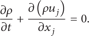
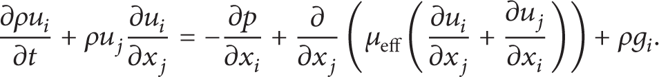
The Momentum Equation. A single momentum equation is solved throughout the domain, and the resulting velocity field is shared among the phases. The momentum equation, shown below, is dependent on the volume fractions of all phases through the properties ρ and μ:
The VOF formulation relies on the fact that two or more fluids or phases are not interpenetrating. For each additional phase, a new variable is introduced such as the volume fraction of the phase in the computational cell. In each control volume, the sum of volume fractions of all phases is unity. The fields for all variables and properties are shared by the phases and represent volume-averaged values, as long as the volume fraction of each of the phases is known at each location. Thus, the variables and properties in any given cell are either purely representative of one of the phases or representative of a mixture of the phases, depending upon volume fraction values.
The tracking of the interfaces between the phases is accomplished by the solution of a continuity equation for the volume fraction of one (or more) of the phases. For the qth phase, this equation has the following form:
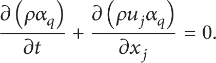
The volume fraction equation will not be solved for the primary phase; the primary-phase volume fraction will be computed based on the following constraint:

Thek-ε Turbulence Model. The standard k-ε model is used to calculate the effective viscosity with the effects of buoyancy:
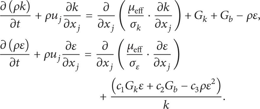
In these equations, G k represents the generation of turbulence kinetic energy due to the mean velocity gradients and this term may be defined as
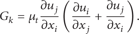
The term G b is the generation of turbulence kinetic energy due to buoyancy and is calculated by

Effective viscosity is the sum of laminar viscosity and turbulent viscosity:
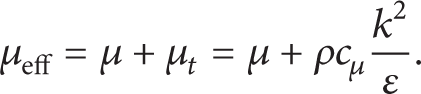
The values for the constants in this k-ε model c1, c2, c3, cμ, σ k , and σε are 1.43, 1.92, 0.09, 1.00, and 1.30, respectively [15].
2.3. Initial and Boundary Conditions
A schematic of gas injection into a steelmaking ladle is shown in Figure 1. Typically, a porous plug is located at the base of the ladle, through which argon is injected into a vessel of molten steel. The injected gas rises to the free surface inducing a turbulent recirculatory flow of liquid because of its buoyancy.
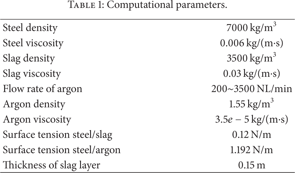
Initially, the steel starts at rest with no blowing through the plug, and the slag layer rests on top of the ladle. At the inlet the velocity of argon is calculated by the flow rates of air and only a vertical gas velocity exists. All velocities are set to zero and wall functions are applied at the walls. At the top of the ladle, a reference pressure of zero is prescribed. The physical properties used for all phases are shown in the Table 1.
Computational parameters.
2.4. Numerical Method
A control volume-based technique was used to convert the nonlinear governing equations to algebraic equations that can be solved numerically. The computational domain is divided by about 58,000 nodes and a fine mesh was used near the slag layer for realistic reconstruction of the moving, air-slag, and slag-molten steel interfaces, as shown in Figure 2. A typical grid independence test (i.e., 34,000, 58,000, and 82,000) of the present numerical calculation was evaluated and according to the results, the grid sizes of 58,000 and 82,000 have almost the same velocity magnitude distribution at the axis of the ladle, which demonstrates that the grid size of 58,000 is accurate enough for the present numerical calculation. SIMPLE algorithm was applied for the pressure-velocity coupling. A segregated and implicit solver was used to solve the governing equations and the second-order accuracy upwind differencing scheme was adopted to improve the accuracy of the solution. The first-order accurate implicit time-stepping scheme is used and the time step size is 0.01 s. In the present study, the criterion for convergence in all cases is the sum of all residuals for the dependent variables less than 10−4. Before the numerical data are time-averaged and exported for analysis, computations were carried out for about 20 s to get statistically steady results.
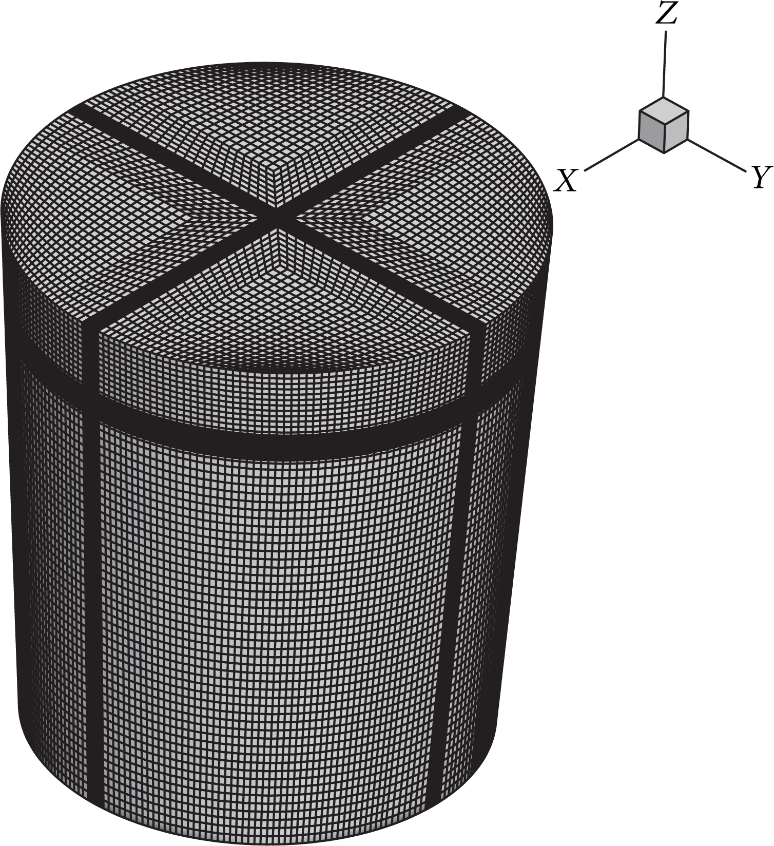
3D computational mesh employed in the present model.
3. Results and Discussion
The time-averaged flow field at main section for all zones including gas, steel, and slag phases at two different gas flows is shown in Figure 3. The flow pattern near the slag layer is very complex, and some vortices appear. Variation of flow patterns is caused by the difference of physical properties between slag and steel. Buoyancy forces from the injected gas give rise to the high steel velocities at the center of the ladle, which are responsible for momentum transfer to their surrounding steel generating its ascending movement to the free surface. When the steel reaches the surface it is directed towards the ladle wall. Thereafter, the steel flow is directed downward along the ladle wall to the bottom, causing one loop in the system. As steel transfers its momentum to the whole bulk by shear stress, it loses velocity. At lower gas flow rate, the steel/slag interface is approximately flat. While the situation for the higher gas flow is somewhat different, the steel in the outskirt regions of the plume “falls down” in the bulk and causes a downward loop in the slag closest, as shown in Figure 4. It was found that bubble plume is not formed by a continuous air phase, but from dispersed bubbles with different shapes and sizes, which ascend to the free surface leaving irregular distances among bubbles throughout its trajectory.

The time-averaged velocity vector on the vertical plane along the gas inlet and the ladle center.

Time-averaged contour of the extent of gas dispersion on the vertical plane along the gas inlet and the ladle center.
The slag eye area is time dependent as shown in Figure 5 and such geometrical data may deviate strongly from momentary values in a dynamic process. Figure 5 is the complete trace of the slag eye area for different gas flow rates, recorded in about 20 s. Due to the lateral motion of the bubble plume, the slag eye area fluctuations are very strong.

The variation of slag area versus the blowing time.
Yonezawa and Schwerdtfeger [9] have carried out model experiments systematically to measure the spout eye area using mercury and some kinds of silicone oils. These various data can be expressed by plotting the Froude number against the nondimensional area (Ase/H m ) as shown in Figure 6. The time-averaged spout eye area in the present work is also shown in Figure 6. It indicates that the time-averaged results obtained by the present model may be somewhat less than actual ones. Anyway, it may be concluded that the agreement between the numerical results and experimental results is rather satisfactory.

Nondimensional time-averaged spout eye area versus Froude number.
Based on their experimental data, Yonezawa and Schwerdtfeger [9] have proposed empirical equations with the following functional relationship:

where Ase is the spout eye area, H m is the depth of the molten steel in the vessel, H s is the thickness of the slag layer, Q g is the air flow rate, and g is the acceleration due to gravity. For predictive applications, the exact function must be evaluated. This is better obtained from the analysis of the numerical data.
A regression analysis of all the calculated data in Figure 6 yields the following relationship:
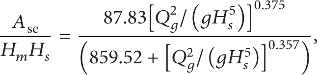
which represents the data points very well as shown in Figure 7.
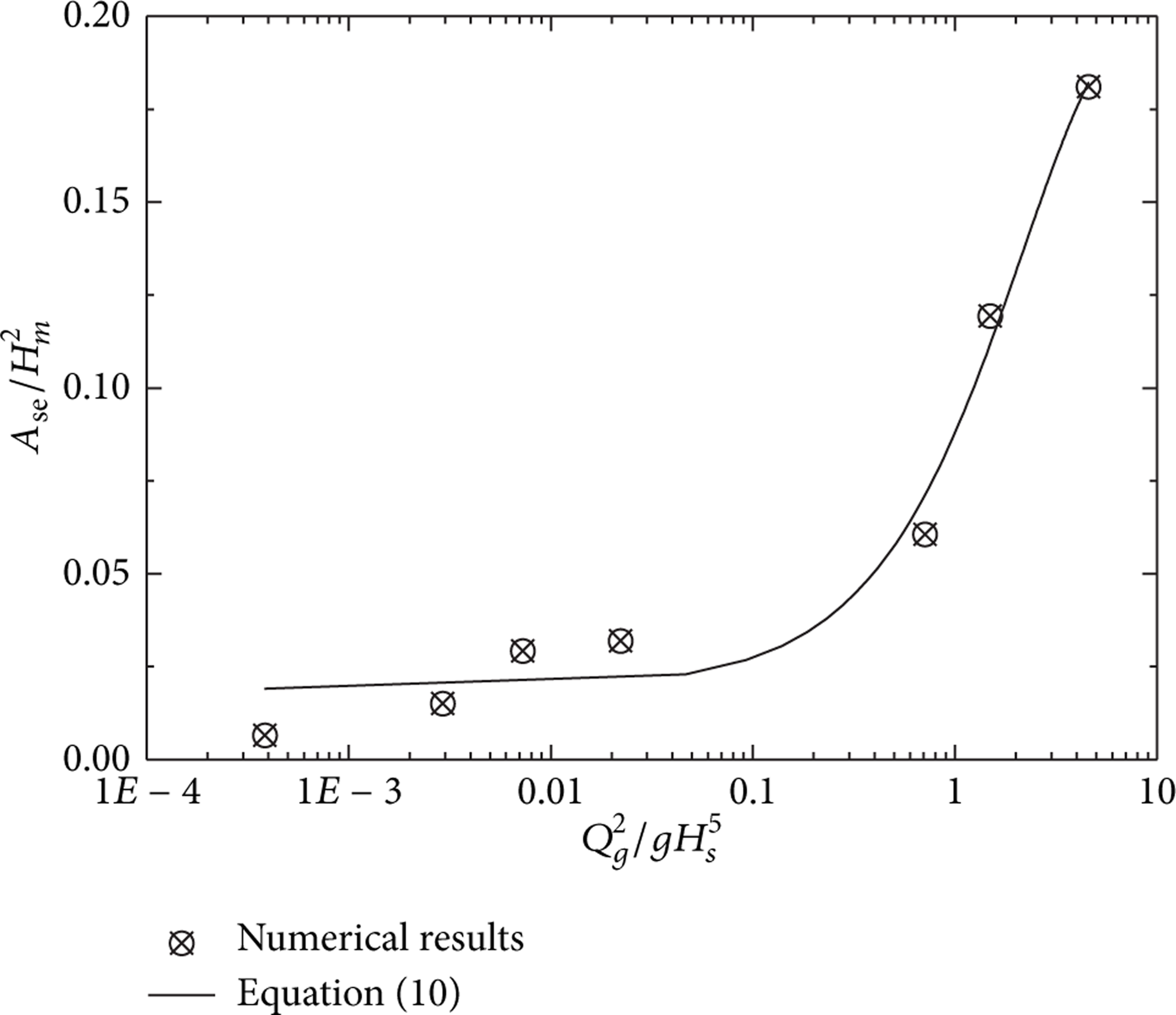
Regression analysis of the time-averaged spout eye area.
4. Conclusions
The present model of a gas-stirred ladle, which takes into account the molten steel, gas, and slag phases, enables us to predict the fluid flow and heat transfer in the very important steel/slag region. This information may be useful in helping us understand metallurgical phenomena such as the separation of nonmetallic inclusions, reoxidation from slag to steel, and reactions between injected gas and steel. The main conclusions of the present work may be summarized as follows.
Gas plume formed above the plug when argon is injected into the molten steel in a ladle. The rising gas bubbles impinge the slag intermittently and the slag eye is created.
The obtained relationship between nondimensional areas of slag eye and the Froude number is in good agreement with the reported data.
Conflict of Interests
The authors declare that there is no conflict of interests regarding the publication of this paper.
Footnotes
Acknowledgments
This work was supported by the National Natural Science Foundation of China (51210007) and the National Key Technology R&D Program of China (2011BAK06B02).