
Abstract
A system to monitor and trace the yields and distribution of agricultural products is an important precision agricultural application. The system can be used to predict the next year's yields or provide the distribution channel of agricultural products from farmers to customers. Existing traceability and monitoring systems, usually, are implemented by using both wireless sensor network (WSN) and radio frequency identification (RFID) techniques. In this paper, we propose a system architecture that only requires WSN techniques and implement it. The implementing system consists of sensor nodes, communication hubs, a communication protocol, and an event detection engine. We define events to trace and monitor agricultural products, and our event detection engine detects those events by using the current location and the status of each sensor node. We describe the overall architecture of the proposed system and implementation details.
1. Introduction
During the past couple of decades, precision agriculture (PA) has emerged with the advances of electronic equipment which has enabled farmers to increase the efficiency of their operations and develop new farming practices. PA is based on numerous technologies and infrastructures such as data gathering and management systems, geographic information systems (GIS), global positioning systems (GPS), microelectronics, wireless sensor networks (WSNs), and radio frequency identification (RFID) technologies [1–6]. Various applications of PA have been proposed and researched extensively. Among many applications, we focus on the agricultural products’ trace and monitoring systems.
Monitoring and tracing systems for the yields and distribution of agricultural products are one of the important PA applications. The results of the systems can be used to predict the next year's yields. Also, we can provide the distribution channel of agricultural products from farmers to customers by using those systems. Most of the existing systems are based on both RFID systems and WSNs. Usually, RFIDs are used to trace agricultural products and measure their yields, and WSNs are for monitoring the environment during the distribution and storage [1].
In this paper, we propose a trace and monitoring system for agricultural products’ yields and distribution based on WSNs. Without RFID technologies, we efficiently trace agricultural products and also measure the yields of agricultural products. If humidity, temperature, and other sensors are added to our sensor nodes, the applicable area of our system can be extended to quality oriented applications. We propose an overall architecture of our proposed system and describe the implementation details of the proposed system.
This paper is organized as follows. In Section 2, we explain the existing WSNs and RFID technologies and various applications of PA based on WSNs and RFIDs. In Section 3, we explain the physical and logical architecture of the proposed system with some diagrams. In Section 4, we describe the implementation details of our proposed system. Finally, in Section 5, we conclude our paper.
2. Related Work
2.1. Wireless Sensor Networks
A wireless sensor network is a system that consists of radio frequency (RF) transceivers, sensors, microcontrollers, and power sources. Wireless sensor networks have some properties, such as self-organizing, self-configuring, self-diagnosing, and self-healing properties. These properties solve problems or enable applications that traditional technologies could not address [3–5].
An obvious advantage of wireless transmission is a significant reduction and simplification in deployment. Wireless sensor nodes allow impossible sensor applications, such as monitoring dangerous, hazardous, unwired, or remote areas and locations. This technology provides nearly unlimited installation flexibility for sensor nodes and increased network robustness. Furthermore, wireless technology reduces maintenance complexity and costs. Wireless sensor networks allow faster deployment and installation of various types of sensors because many of these networks provide self-organizing, self-configuring, self-diagnosing, and self-healing capabilities to the sensor nodes [3–5].
Wireless sensor node technology allows MEMS (micro-electro-mechanical systems) sensors to be integrated with a sensor node with extremely low cost, small size, and low power requirement. MEMS pressure sensors, temperature sensors, humidity sensors, and various capacitive sensors for proximity, position, velocity, acceleration, and vibration measurements have been integrated to wireless sensor nodes [7]. These MEMS sensors enable quality oriented applications.
2.2. Radio Frequency Identification (RFID)
RFID systems are comprised of three main components such as the tag or transponder, the reader or transceiver that reads and writes data to a transponder, and the computer containing database and information management software. RFID tags can be active, passive, or semipassive. Passive and semipassive RFIDs send their data by reflection or modulation of the electromagnetic field that was emitted by the reader. The typical reading range is between 10 cm and 3 m [1, 8].
The major drawback of RFID is the limited reading range of about 20 cm, compared to other 13.56 MHz passive RFID tags (ISO15693). Sensor tags with UHF interfaces extend the reading range to a few meters and allow for automated readout during the unloading of the transport, but their signals cannot penetrate metals or liquids. Accessing passive tags during transport in a packed container is far beyond technical feasibility.
2.3. PA Applications
According to [3], there are various PA applications that have been studied and addressed. Particularly, we briefly describe RFID-based traceability systems of [3] in the following. Inexpensive, disposable RFID biosensor tags were studied. These tags were used for history checking and contamination and inventory control on food products. The biosensor tags were based on an acoustic wave platform and used antigen-antibody reaction to detect bacteria. Also, some researchers introduced the potential of RFID tags for smart packaging, automatic checkout, smart appliances, smart recycling, and marketing [3].
An on-the-road monitoring system for animals during transportation was developed. The system included sensors installed in the animal compartment to identify the animals and to monitor the air-quality, vibration, and animal behaviors. A GPS provided the location of the vehicle. A data transfer unit regularly sent data to a service center via the GSM network. It was reported that the system greatly improved animal welfare during handling and transportation [3].
A field data acquisition system was developed to collect data for crop management and spatial-variability studies. The system consisted of a data collection vehicle, a manager vehicle, and data acquisition and control systems on farm machines. The system collected data of soil water availability, soil compaction, soil fertility, biomass yield, leaf area index, leaf temperature, leaf chlorophyll content, plant water status, local climate data, insect-disease-weed infestation, grain yield, and so forth. The data collection vehicle retrieved data from farm machines via a WLAN and analyzed, stored, and transmitted the data to the manager vehicle wirelessly [3].
A greenhouse monitoring and control system was developed to collect outdoor and indoor climate data in Portugal. Several solar-powered data acquisition stations (SPWAS) were installed indoor and outdoor to measure and monitor the climate data. RF links were established among multiple SPWASs and a base station, which was used to control the SPWASs and to store the data [3].
3. Architecture of the Proposed System
The architecture of our proposed yields and distribution trace system for agricultural products is in Figure 1. We assume that workflow is as follows. First, picked agricultural products are stored in farms’ local cold warehouses for a time. Picked agricultural products are packed in boxes that sensors are attached to. Agricultural products stored in farms are transported to an APC (agricultural products processing center). The APC sorts and repacks agricultural products transported from farms and stores to its cold warehouse. The agricultural products are shipped whenever wholesalers require products.
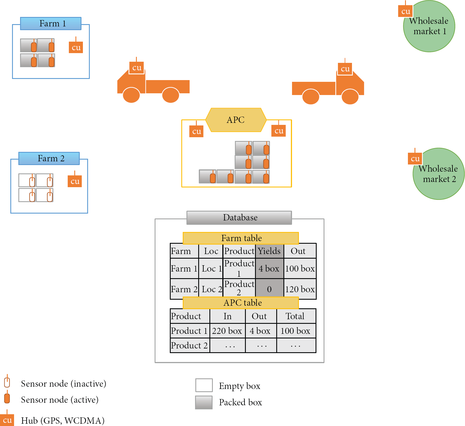
The overall architecture of the proposed system.
Each farm has boxes that are equipped with sensor nodes. A sensor node has some functionalities such as temperature sensors, humid sensors, gyro sensors, infrared sensors, CPU, and wireless communication functions. CPU and wireless communication functions are mandatory. Other functions may be optionally applied to a sensor node. Also, a communication hub is placed in each farm's local cold warehouse. The communication hub gathers data from sensor nodes in boxes and processes sensor data. Also, transport vehicles that deliver agricultural product boxes may have one or more communication hubs. Communication hubs send gathered data to a central server with their location data. The server stores sent data from each communication hub to a local database.
Sensor nodes of the proposed system are inactive status when they are not used. Infrared sensor and gyro sensor of a sensor node detect whether boxes are used or not. The sensor node is activated when agricultural products are put into a box and the box is moved. A communication hub sends gathered data from sensor nodes and location data of the communication hub. The location data is used to detect and trace the boxes that are equipped with sensor nodes.
4. Implementation of the Proposed System
In this section, we describe the implementation details of our proposed system. We focus on software components rather than hardware components. Mandatory requirements of hardware components like sensor nodes and communication units are shown in Table 1. Figure 2 shows sensor nodes, a hub, and box equipped with a sensor node. A sensor node is installed in a box as in Figure 2(b) to detect whether the box is filled with agricultural products.
Required specifications of hardware components.


Deployed sensor nodes and a communication hub.
Figure 3 shows the database schema for the proposed system. Temperature_humidity and CO2 tables are used when a sensor node has humidity, temperature, and CO2 sensors. Hub table is used to register hubs. Each hub has cell phone number for its WCDMA module. Hub table stores the phone number and the ID of a hub. Location table stores the locations of hubs. Each hub periodically sends its location with gathered sensor data. Tag table is used to register sensor nodes.

Database schema for the proposed system.
Place table registers the location of farms, APCs, and wholesalers. Our system traces and monitors the distribution path and yields of agricultural products by using this table and locations of hubs. Event table stores detected events by our event detection engine. We define four events as shown in Table 2. The event detection engine uses those tables and input data stream from hubs to detect these events. Event 1 occurs when a box containing agricultural products has moved into a registered place. Event 2 occurs when the box has moved out of a registered place. Finally, event 3 means that the box is moving from a place to another place. Detected events of a sensor node are stored in event table.
Definition of events.

Algorithm 1 shows the algorithm of our event detection engine. This algorithm works whenever a central server receives data from a hub. First, it finds a place where a sensor exists by querying which geo_fence contains the location of the sensor. Geo_fence is given by users, and it is used to compensate the GPS error. Then, the algorithm checks the previous event of the sensor and decides the event of the sensor as in Figure 3. If previous event is null, it means that the sensor is activated at the place, and event 0 is assigned. If previous event is 1, and the current place is null, the event of the sensor node is 3 which means that the sensor node is moving. If the previous event is 3, and the current place is not null, the event of the sensor node is 1. Also, if the previous event is 2, and the current place is null, the sensor node starts moving out of a place.
//detect current place Sql = select from (select sqrt(pow(A.x-loc.latitude, 2) + pow(A.y-loc.longitude,2)) dist, A. from place A) B where B.dist < geo_fence; Place = Excute_query(Sql); //check the previous event of a sensor and detect event Sql = select Prev_event = Excute_query(sql); if (Place == null) { if (Prev_event == null) insert event 0; else if (Prev_event.event == 1) insert event 2, Prev_event.pname; } else { if (Prev_event.event == 0 && Prev_event == null) insert event 1, Place.pname; else if (Prev_event.event == 1 && Prev_event.pname != Place.pname) { insert event 2, Prev_event.pname; insert event 3, Prev_event.pname; insert event 1, Place.pname; } else if (Prev_event.event == 2) { insert event 3, Prev_event.pname; insert event 1, Place.pname; } }
Figure 4 shows an example of event detection algorithm. There are three places and transport vehicles with CUs. Three boxes with sensor nodes are moved between places by transport vehicles. At time t1, sensor 3 (S3) sends data through the hub of place 1. Since the previous event of S3 is null and the current place is not null, we decide that event 1 occurs. At time t2, S3 sends its data through the hub of place 2. The previous event of S3 is 1, and the current place is place 2 so we decide the events are 2 and 1. It means that the sensor node was moved out of place 1 and moved in place 2. At t2, sensor 1 (S1) sends its data through the hub of a transport vehicle. The previous of S1 is 1, and the current place is null, so the events of S1 are 2 and 3 which means that the sensor node has been moved out and on the road.

Example of detecting events.
Figure 5 shows our communication protocol between a server and hub (coordinator in this figure). A sleeping hub is woken up by the server. The server sends an SMS (short message service) message to the hub to wake up. Then, the hub sends a connection request to the server. After the connection between the server and the hub is established, the server sends configuration information to the hub such as transmission period. The hub starts to send the location data and gathered sensor data to the server periodically.

Communication protocol between hub and server.
5. Conclusion
In this paper, we proposed a system to trace and monitor agricultural products’ yields and distribution channel with WSN techniques. Also, we implemented the proposed system. The implemented system consists of hardware components such as sensor nodes and hub and software components such as communication protocol between hub and server and event detection engine. We defined events to trace and monitor agricultural products. The event detection engine detects events by using the current location of each sensor node, previous event, and registered places. If the sensors such as temperature, humidity, or others are added to our sensor nodes, the applicable area can be extended.
Footnotes
Conflict of Interests
The authors declare that they have no conflict of interests regarding the publication of this paper.
Acknowledgments
This research was supported by Basic Science Research Program through the National Research Foundation of Korea (NRF) funded by the Ministry of Education, Science and Technology (2012R1A1A2A10042015) and Technology Development Program for “Agriculture and Forestry” or “Food” or “Fisheries,” Ministry for Food, Agriculture, Forestry and Fisheries, Republic of Korea.