
Abstract
This study aims to find the optimum performance and emission characteristics of single cylinder variable compression ratio (VCR) engine with different blends of Annona methyl ester (AME) as fuel. The performance parameters such as specific fuel consumption (SFC), brake thermal efficiency (BTE), and emission levels of HC, CO, Smoke, and NO x were compared with the diesel fuel. It is found that, at compression ratio of 17: 1 for A20 blended fuel (20% AME + 80% Diesel) shows better performance and lower emission level which is very close to neat diesel fuel. The engine was operated with different values of compression ratio (15, 16, and 17) to find out best possible combination for operating engine with blends of AME. It is also found that the increase of compression ratio increases the BTE and reduces SFC and has lower emission without any engine in design modifications.
1. Introduction
Annona squamosais a member of the family of custard apple trees called Annonaceae and a species of the genus Annonaknown mostly for its edible fruits Annona [1]. It is commonly found in India and cultivated in Thailand and originates from the West Indies and South America. Annona squamosaproduces fruits that are usually called sugar apple or custard apple in English, sitafal in Marathi, sharifa in Hindi, and sitaphalam in Tamil, in India and corossolier, cailleux, and pommier cannelle in French [2]. It is mainly grown in gardens for its fruits and ornamental value. It is considered beneficial for cardiac disease, diabetes, hyperthyroidism, and cancer. The root is considered a drastic purgative [3].
As per the US department of energy [4], the world's oil supply will reach its maximum production and midpoint of depletion sometime around the year 2020. Future projections indicate that the only feasible option is the production of synthetic fuels derived from nonpetroleum sources [5]. In diesel engines, a significant research effort has been directed towards using vegetable oils and their derivatives as fuels. Nonedible vegetable oils in their natural form called straight vegetable oils (SVO), methyl or ethyl esters known as treated vegetable oils, and esterified vegetable oils referred to as biodiesel fall in the category of biofuels. Biodiesel is considered as a promising alternative fuel for use in diesel engines, boilers, and other combustion equipment. These are biodegradable, can be mixed with diesel in any ratio, and are free from sulphur. Although biodiesel has many advantages over diesel fuel, there are several problems that need to be addressed such as its lower calorific value, higher flash point, higher viscosity, poor cold flow properties, poor oxidative stability, and higher emission of nitrogen oxides [6]. Biodiesel obtained from some feed stocks might produce slightly more oxides of nitrogen (1–6%) than the fossil origin fuels but can be managed with the utilization of blended fuel of biodiesel and high speed diesel fuel [7]. It is found that the lower concentrations of biodiesel blends improve the thermal efficiency. Most of the research studies concluded that, in the existing engine design parameters operating, a 20% blend of biodiesel with diesel works considerable reduction in emission and brake specific fuel consumption is also observed [8]. Effect of injection parameters [9–15], spray [16], injection timing, and compression ratio [2, 3, 17–19] has been studied in detail at many places. Many researchers indicated that the need of research in the areas of engine modifications is required so as to suit higher blends without severe drop in performance and reduction in emission. Effect of variations in these parameters has been studied taking one or more parameters at a time [20–22]. These studies were carried out in different types of engines (stationary/mobile; single cylinder/multicylinder; constant speed/variable speed) with biodiesel prepared from different oil origin. The present study is to find the optimum compression ratio and different blends of AME for better performance and lower emission level of diesel blended with biodiesel obtained from Annona methyl ester.
2. Experimental Section
An experimental setup is developed to undertake the performance evaluation and emission characteristics evaluation of a variable compression ratio compression ignition engine fuelled with Annona biodiesel and its blends with diesel oil. The experimental setup is suitably developed to conduct various test runs under different working conditions to evaluate the thermal performance and emission constituents of a biodiesel run engine in comparison with that of a conventional diesel engine.
2.1. Description of Experimental Setup
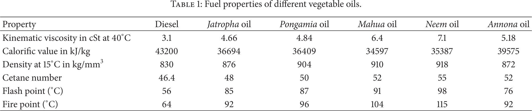
The experimental setup consists of a single cylinder, cooled water, variable compression ratio compression ignition engine, eddy current dynamometer as loading system, fuel supply system for both diesel oil supply and biodiesel supply, water cooling system, lubrication system, and various sensors and instruments integrated with computerized data acquisition system for online measurement of load, air and fuel flow rate, instantaneous cylinder pressure, injection pressure, position of crank angle, exhaust emissions, and smoke opacity. Figure 1 is the photographic image of the experimental setup used in the laboratory to conduct the present study. The schematic diagram of the experimental test setup is shown in Figure 2. This test bed has a provision to change its compression ratio by raising or lowering bore head of the engine. The setup enables the evaluation of thermal performance and emission constituents of the VCR engine. The thermal performance parameters include brake power, brake mean effective pressure, brake thermal efficiency, volumetric efficiency, brake specific fuel consumption, exhaust gas temperature, heat equivalent of brake power, and heat equivalent of exhaust gas. Commercially available lab view based engine performance analysis software package, EnginesoftLV1, is used for on line performance evaluation. The exhaust emissions of the engine are analyses using an exhaust gas analyzer. The software stores the data of pressures and volumes corresponding to a particular crank angle location for plotting the pressure-volume and pressure-crank angle curves. The constituents of the exhaust gas measured are CO (% and ppm), CO2 (%), O2 (%), HC (ppm), NO x (ppm), and SO x (ppm). The smoke intensity is measured in terms of Hartridge smoke unit (HSU in %)/K (the light absorption coefficient (m − 1). The range of carbon monoxide meter was 0 to 2 percent (least count 0.001%) and for nitric oxide meter it was 0 to 2000 ppm (least count 1 ppm). The properties of different vegeTable oils and their comparison with diesel are shown in Table 1.
Fuel properties of different vegetable oils.
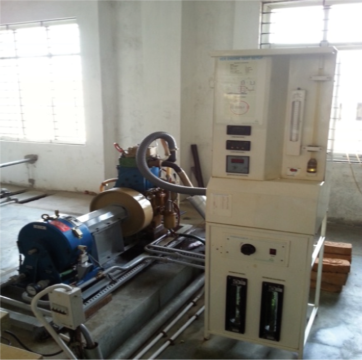
Photographic image of the experimental setup.

Schematic diagram of the experimental setup.
2.2. Compression Ratio Setting
The engine with fixed compression ratio can be modified by providing additional variable combustion space. There are different arrangements by which this can be achieved. Tilting cylinder block method is one of the arrangements which can be used to vary the combustion space volume. The engine is made to operate as a variable compression ratio (VCR) engine by providing a tilting block arrangement to suitably change the compression ratio (CR) to the desired value in the given range without stopping the engine and without altering the combustion chamber geometry. The tilting cylinder block arrangement consists of a tilting block with six Allen bolts, a compression ratio adjuster with lock nut, and compression ratio indicator. For setting a chosen compression ratio, the Allen bolts are to be slightly loosened. Then, the lock nut on the adjuster is to be loosened and the adjuster is to be rotated to set a chosen compression ratio by referring to the compression ratio indicator and to be locked using lock nut. Finally all the Allen bolts are to be tightened gently. The compression ratios considered for conducting the experiments are 15, 16, and 17. Due to rough running of the engine and greater vibration, the compression ratio below 15 is not set though there is a provision to set the CR value up to 12.
2.3. Specifications of the Apparatus
In the test setup there are several instruments that have been used for the purpose of the experiment. Brief specifications of the instruments are given below.
2.3.1. Diesel Engine
Manufacturer: Kirloskar Oil Engines Limited
Type of Engine: vertical, 4-stroke single cylinder, variable compression ratio engine
Maximum Power: 8 HP
Max brake power: 6.02 kW
Rated Speed: 1800 rpm
Bore and stroke: 87.5 × 110 (mm).
2.3.2. Smoke Meter
Smoke meter is used to determine the smoke density of the engine exhaust. The AVL 437 smoke meter has been designed for simple one man operation either from alongside a vehicle for either free acceleration or steady state test procedures. Control is via a compact and rugged handset with a digital L.C.D. display.
Type: AVL 437 smoke meters
Make: AVL India Pvt. Ltd
Measuring range: 0 to 100 HSU.
2.3.3. Exhaust Gas Analyzer
Exhaust gas analyzer is used to determine the emissions such as HC, CO, CO2, and NO x .
Manufacturer: SMS Autoline Equipments Private Limited
Type: Crypton 290 five gas analyzer.
2.4. Testing Procedure
Engine was started and warmed up at low idle, long enough to esTablish the recommended oil pressure and was checked for any fuel and oil leaks. The engine was run on no-load condition and speed was varied from 1550 rpm to 1650 rpm. Engine was run to gain uniform speed, after which it was gradually loaded. Experiments were conducted at different loads such as 0 kg, 3 kg, 6 kg, 9 kg, and 12 kg. The engine was run for 10 minutes and data were collected during last 4 minutes. For different blends of AME, performance tests were carried out at three different compression ratios. The exhaust gas is sampled from exhaust pipeline and passed through a four gas analyzer for measurement of carbon monoxide, carbon dioxide, smoke, unburnt hydrocarbon, and oxides of nitrogen present in exhaust gases. A smoke meter is used for measurement of smoke capacity. The experimental uncertainties are shown in Table 2.
Experiment uncertainties.

All engine performance and emissions data are corrected to the standard atmospheric conditions before carrying out the engine test. It is given below.
The power correction factor used was (according to Turkish Standards, TS 1231)
where

T a is ambient temperature (K), P a is ambient pressure (kPa), q is fuel delivery rate (mg/cycle), and r is compressor pressure ratio (for naturally aspirated engines, r = 1).
Gaseous emissions data including measures of CO, CO2, NO x , and HC were measured according to SAE J816B specifications and procedures. Statistical analyses were also adopted and measures of performance were corrected to standard atmospheric conditions (SAE J816B). Gaseous emission data included nondispersive infrared (NDIR) analysis of carbon monoxide (CO), carbon dioxide (CO2), and hydrocarbons (HC) and chemiluminescent measurements of NO x and oxygen (O2). The emissions measurements were done according to specifications and procedures described on SAE Engine Test Code J816b (SAE net flywheel horsepower of engine, as applied to this vehicle, when equipped with operating accessories including oil and water pumps, alternator, air cleaner, fan, and muffler, corrected to 500″ (152 m) altitude with 38″ (9.5 mm) Hg vapour pressure, 29.38″ (746 mm) Hg observed barometer, and 85°F (29°C) air).
3. Results and Discussion
Test engine was run with different blends of AME & different compression ratio for various loads and time for 10 cc fuel consumption was calculated.
3.1. Effect of Compression Ratio on Performance and Emission Characteristics
3.1.1. Specific Fuel Consumption (SFC)
Figure 3 shows the variation of SFC for different blends of AME and neat diesel fuel with different compression ratios. It is observed that the SFC gradually decreases with increasing compression ratio. At maximum load with the compression ratio of 17, the SFC for A20 is 0.301 kg/kW-hr and 3% reduction of SFC is achieved when compared with the neat diesel fuel. This is due to increase in compression ratio which leads to reduction in dilution of charge by residual gases, which results in better BTE and lower SFC. Further, it is also due to low volatility and higher cetane number of biodiesel when compared to diesel which will result in improved combustion at high compression ratio. According to blend ratio, the SFC for A20 is lower than that of other blends under high compression ratio and full conditions. At high percentage of blends, the SFC increases. This is due to fuel density, viscosity, and heating value of the biodiesel. However increase in SFC is observed with lower compression ratio because of slow combustion process.

Load versus SFC for CR 15, 16, and 17.
3.1.2. Brake Thermal Efficiency (BTE)
Figure 4 shows the variation of BTE for different blends of AME and neat diesel fuel with different compression ratios. It is observed that the BTE gradually increases with increasing compression ratio. At maximum load with the compression ratio of 17, the BTE for A20 is 30.67% and it is almost equal to the neat diesel fuel (31.47%). This is due to increase in compression ratio which ensures better air-fuel mixing and faster evaporation and leads to complete combustion. Further, it is also due to biodiesel blends having low volatility when compared to diesel fuel and therefore the improvement in their combustion characteristics at high temperature resulted from higher compression ratio than the improvement in case of diesel fuel with the same compression ratio rise. According to blend ratio, the BTE is reduced with the increasing concentrations of biodiesel in the blend at all compression ratios. The BTE for A20 is higher than that of other blends under higher compression ratio and full load conditions. This is due to presence of excess amount of oxygen in A20 which resulted in improved combustion when compared to the neat diesel fuel. Whereas, reduction in compression ratio resulted in lowering the BTE due to lower compression pressure and temperature, slow combustion process, and more dilution by residual gas.
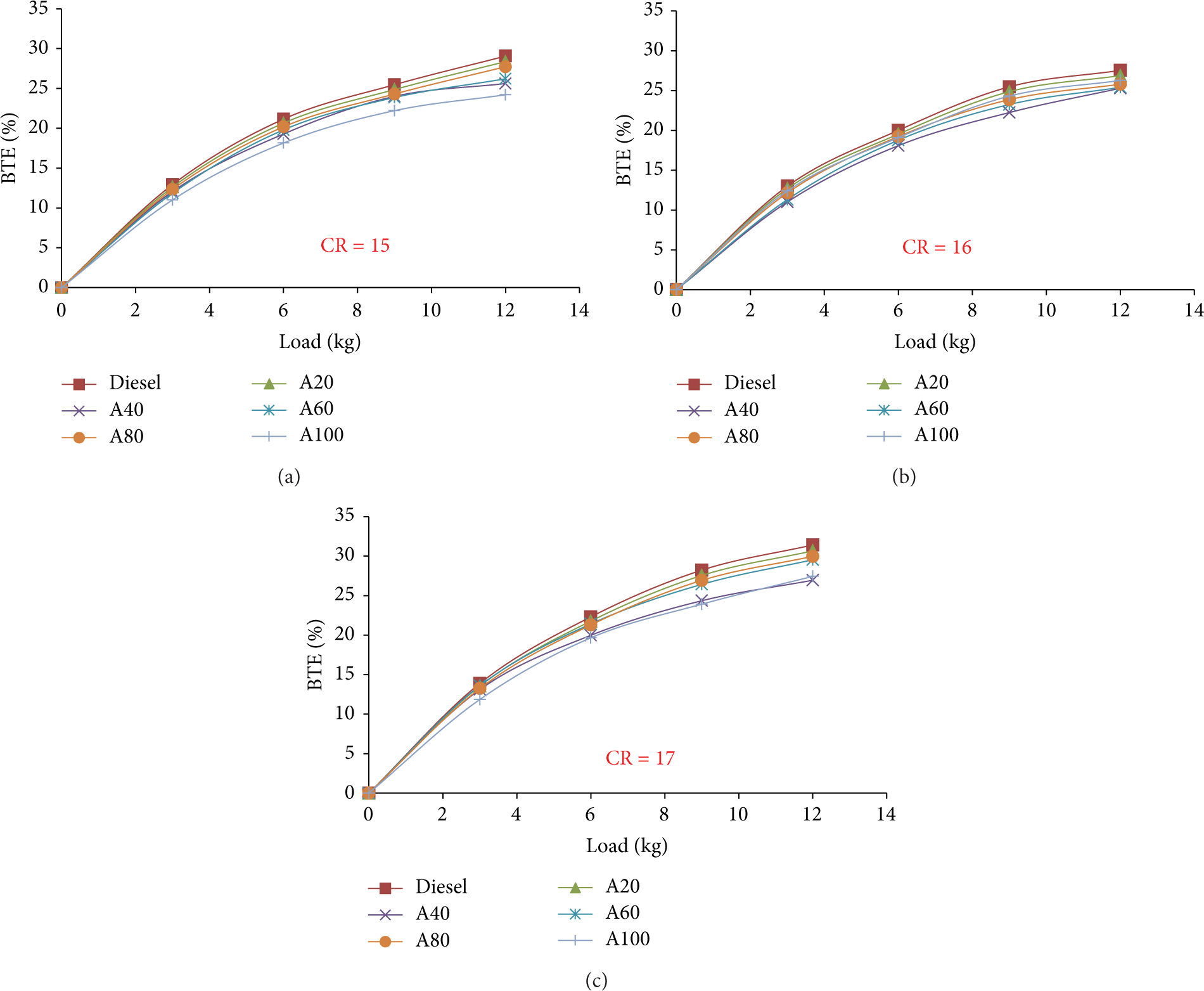
Load versus BTE for CR 15, 16, and 17.
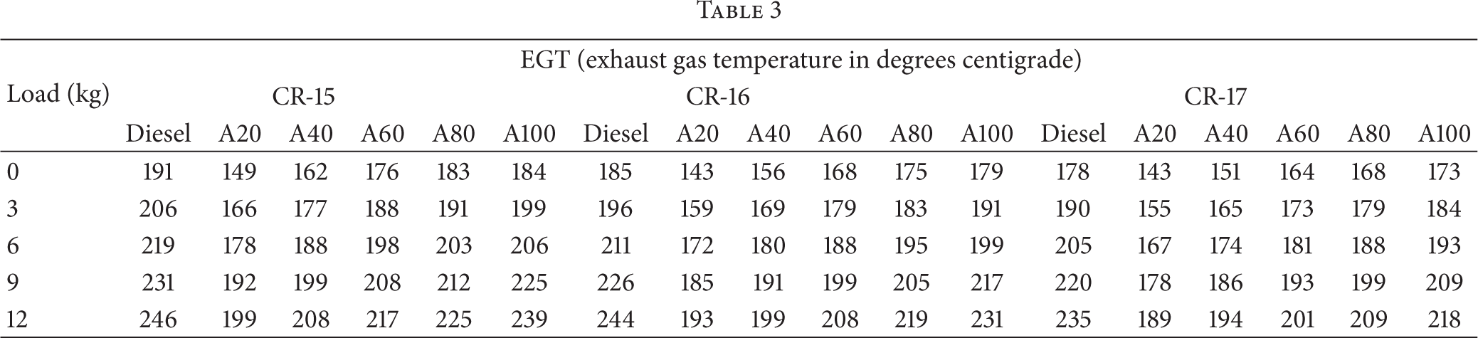
3.1.3. Exhaust Gas Temperature: (EGT)
Figure 5 shows the variation of EGT for different blends of AME and neat diesel fuel with different compression ratios. It is observed that the EGT gradually decreases with increasing compression ratio (see Table 3). At maximum load with the compression ratio of 17, the EGT for A20 is 189°C and 19.6% reduction of EGT is achieved when compared with the neat diesel fuel. This is due to shifting of the combustion process slightly to the earlier stroke of the cycle at high compression ratio. Hence, more of the fuel energy is utilized effectively for developing brake power and leads to reduction in exhaust gas temperature. According to blend ratio, the EGT increases with the increasing concentrations of biodiesel in the blend at all compression ratios. The EGT for A20 is lower than that of other blends under higher compression ratio and full load conditions. This is due to the lower calorific value of blended fuel when compared to the neat diesel fuel and lesser temperature at the end of compression. Further, lower exhaust loss may be one of the possible reasons for higher performance.

Load versus EGT for CR 15, 16, and 17.
3.1.4. Carbon Monoxide (CO)
Figure 6 shows the variation of CO for different blends of AME and neat diesel fuel with different compression ratios. It is observed that the CO gradually decreases with increasing compression ratio. At maximum load with the compression ratio of 17, the CO for A20 is 0.03 ppm and 40% reduction of CO is achieved when compared with the neat diesel fuel. This is due to complete combustion; less dilution of charge by residual gases accelerates the carbon oxidation to form carbon dioxide. Further, it is also due to increase in compression ratio which actually increases the air temperature inside the cylinder and consequently reduction in delay period causes better and complete burning of the fuel and lowers the CO emissions. According to blend ratio, the CO emission increases with the increasing concentrations of biodiesel in the blend at all compression ratios. The CO emission for A20 is lower than that of other blends under higher compression ratio and full load conditions. This is due to presence of additional oxygen content in the biodiesel, which enhances the complete combustion and leads to reduction in CO emission. The carbon monoxide emissions are increased at lower compression ratio due to more dilution of fresh air with residual gases, lower compression temperature, and poor mixing of fuel and air.
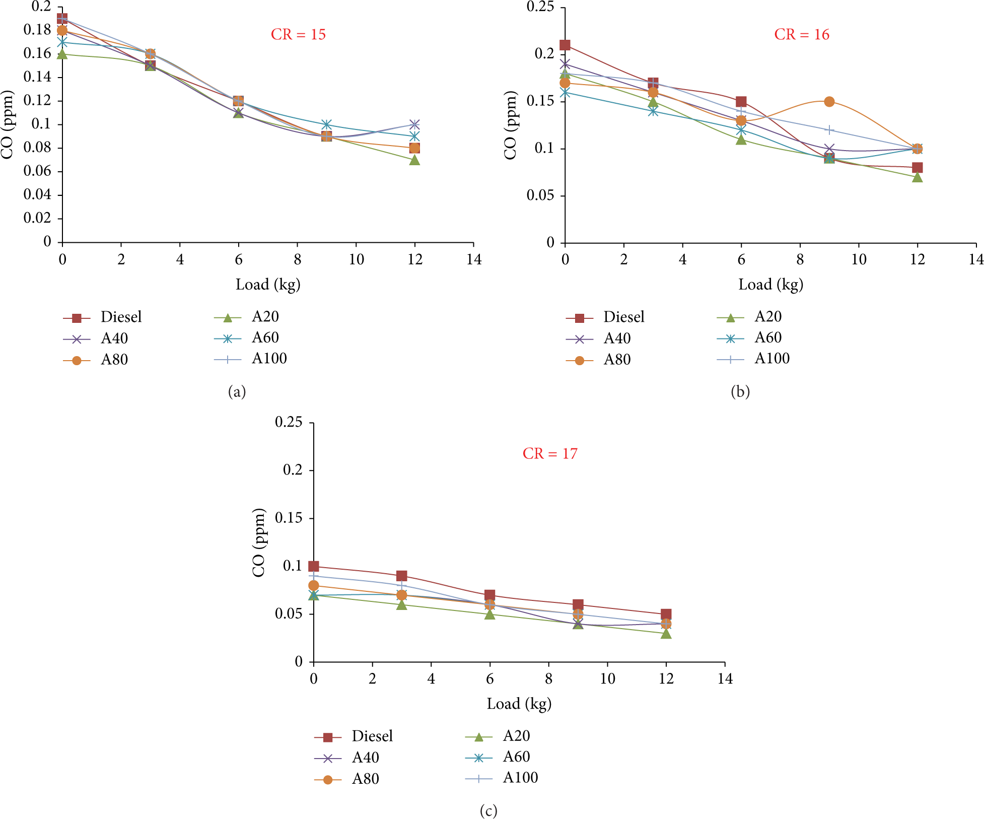
Load versus CO for CR 15, 16, and 17.
3.1.5. Hydrocarbon (HC)
Figure 7 shows the variation of HC for different blends of AME and conventional diesel fuel with different compression ratios. It is observed that the HC gradually decreases with increasing compression ratio. At maximum load with the compression ratio of 17, the HC for A20 is 23 ppm and 23.33% reduction of HC is achieved when compared with the neat diesel fuel. This is due to increase in the air temperature at the end of compression stroke, enhancement in combustion temperature, and reduction in charge dilution which leads to complete combustion and reduction in hydrocarbon emissions. This is also because of better combustion of biodiesel inside the combustion chamber due to the availability of oxygen in biodiesel when compared to neat diesel fuel. According to blend ratio, the HC emission increases with the increasing concentrations of biodiesel in the blend at all compression ratios. The CO emission for A20 is lower than that of other blends under higher compression ratio and full load conditions. This is due to longer ignition delay and accumulation of fuel in the combustion chamber which may cause higher HC emission. Further it is also found that increase in hydrocarbon emission is observed with reduction in compression ratio, due to slow combustion process.
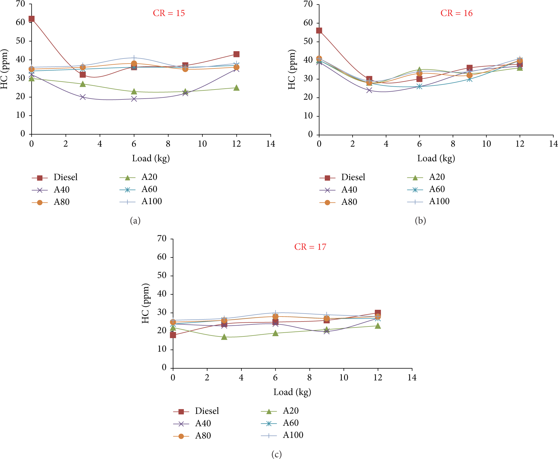
Load versus HC for CR 15, 16, and 17.
3.1.6. Smoke
Figure 8 shows the variation of smoke for different blends of AME and conventional diesel fuel with different compression ratios. It is observed that the smoke gradually decreases with increasing compression ratio. At maximum load with the compression ratio of 17, the smoke for A20 is 17.6 HSU and 21.4% reduction of smoke is achieved when compared with the neat diesel fuel. This may be due to biodiesel which consists of two oxygen atoms which lead to the oxidation of soot and thereby reducing the soot emission. Further, it is also due to better oxidation environment and existence of higher temperature and pressure at higher compression ratio. Also it reconfirms the HC and CO emissions curve.

Load versus Smoke for CR 15, 16, and 17.
3.1.7. Oxides of Nitrogen (NO x )
Temperature plays a vital role in NO x formation. It also depends upon the compression ratio, equivalence ratio, geometry of the combustion chamber, advanced fuel injection, and pressure and temperature of the inlet air. Figure 9 shows the variation of NO x for different blends of AME and conventional diesel fuel with different compression ratios. It is observed that the NO x gradually increase with increasing compression ratio. At maximum load with the compression ratio of 17, the NO x for A20 is 740 ppm and it is almost equal to the neat diesel fuel 734 ppm. This is due to increase in compression ratio and increase in the combustion pressure and temperature which accelerates the oxidation of nitrogen to form oxides of nitrogen. Further it is also due to increase in compression ratio and increase in the combustion temperature which in turn increases the compression ratio which leads to increase in NO x emission. At high compression ratio, ignition delay reduces and peak pressure increases resulting in high combustion temperature and leads to an increase in NO x emission. According to blend ratio, the NO x emission increases with the increasing concentrations of biodiesel in the blend at all compression ratios. The NO x emission for A20 is lower than that of other blends under higher compression ratio and full load conditions. This NO x emission increases for all blends due to oxygen present in the biodiesel which may provide excess oxygen for NO x formation. Further, the biodiesel contains more double bonded molecules than petroleum derived fuels. These double bonded molecules have a higher adiabatic flame temperature and lead to higher NO x emission. Further it is also found that decrease in NO x emission is observed with reduction in compression ratio due to lower combustion temperature and pressure. At low compression ratio, the premixed burning is high due to longer ignition delay resulting in lower NO x emission.

Load versus NO x for CR 15, 16, and 17.
4. Correlation Analysis of Compression Ratio and Blend Ratio
It is concluded that the compression ratio of 17: 1 for A20 at maximum load shows better performance and lower emission level when compared to that of neat diesel fuel and other blends of AME. For that compression ratio of 17: 1, the correlation analysis between compression ratio, blend ratio, and NO x , BSFC was studied and is given in Figure 10.

Variation of BSFC with load for different blends at CR = 17.
During the experimental investigation on the relationship between load and BSFC, it was found that load increases with decrease in BSFC as shown in Figure 8. A first order differential equation can give the slope between the load and BSFC. By differentiating the slope equation y = − 0.01x + 0.514 (A20) gradient between BSFC can be found as −0.01. Every single percentage increase in load may result in increase of −0.01 units.
During the experimental investigation on the relationship between load and NO x , it was found that load increases with increase in NO x as shown in Figure 11. A first order differential equation can give the slope between the load and NO x . By differentiating the slope equation y = 58.106x + 3.966 (A20) gradient between NO x can be found as 58.106. Every single percentage increase in load may result in increase of 58.106 units.
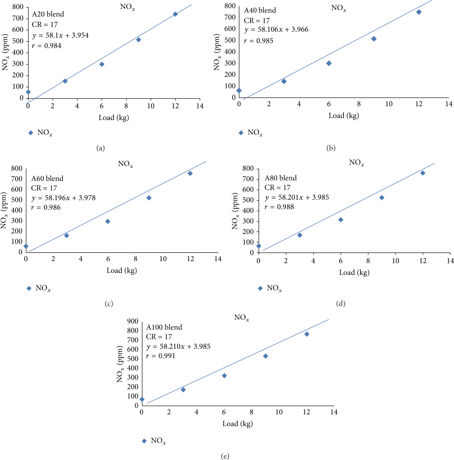
Variation of NO x with load for different blends at CR = 17.
5. Conclusions
The performance and emission characteristics of different blends of AME at different compression ratios are compared with neat diesel fuel. The summary of conclusions is given below.
It is concluded that the compression ratio of 17: 1 for A20 at maximum load shows better performance and lower emission level when compared to that of neat diesel fuel and other blends of AME.
At compression ratio of 17: 1, the SFC for A20 is 0.301 kg/kW-hr and 3% reduction of SFC is achieved when compared with the neat diesel fuel at maximum load. The BTE for A20 is 30.67% and it is almost equal to the neat diesel fuel (31.47%). The EGT for A20 is 189°C and 19.6% reduction of EGT is achieved when compared with the neat diesel fuel at maximum load.
The CO, HC, and smoke emission reduced to 40%, 23.33%, and 21.4%, respectively, for A20 blended fuel with the compression ratio of 17: 1 having been achieved when compared with the neat diesel fuel at maximum load. Further, there is a marginal increase of NO x for all blended fuel of AME.
Finally, it can be concluded that the A20 blended fuel can be used as alternative fuel for CI engine. Particularly at compression ratio of 17: 1, better engine performance and lower emissions can be achieved without any change in engine modifications.
Conflict of Interests
The authors declare no conflict of interests.
Footnotes
Acknowledgment
The authors would like to thank the staff members of Internal Combustion Engineering Department, University College of Engineering Villupuram for their support in carrying these tests.