
Abstract
Underwater acoustic sensor networks (UASNs) have attracted significant attention recently. Localization is one of the most important issues associated with UASNs. Most of the existing underwater localization algorithms require time synchronization. However, time synchronization is difficult to be achieved in the underwater networks. The beam width and three-dimensional direction of underwater acoustic sensor nodes are ignored by the existing underwater localization algorithms. This will increase the difficulty to avoid time synchronization. We develop a loop assisted synchronization-free localization to achieve synchronization-free localization algorithm when taking into account the beam width and direction of the underwater nodes. We propose link detection stage to get link state information (symmetry and length). In addition we introduce a loop-assisted localization method to solve the problem of asymmetric link ranging without time synchronization. Finally, we propose an intersections based location estimation mechanism for error problem in practical measurement and we improve the localization accuracy. The simulation results and experimental results verify the effectiveness and feasibility of the proposed work.
1. Introduction
About three-quarters of the earth is covered with water; it is can be said that most of the regions of the world are water environment and 96% of the water environment is the marine environment. With the development of science and technology, in order to better explore the vast unexplored underwater areas, underwater acoustic sensor networks (UASNs) have attracted significant attention, recently. UASNs can improve ocean exploration and can be widely used in many underwater applications, including oceanographic data collection, warning systems for natural disasters, ecological applications, military underwater surveillance, assisted navigation, and industrial applications [1–8].
Localization is one of the most important issues associated with underwater acoustic sensor networks, especially when sensor nodes are randomly deployed. In many underwater applications such as animal tracking and disaster prevention the sensed data should be tagged with location information. Location information can also support underwater topology control, MAC protocol, and routing protocol; for example, location-based routing protocol needs to be supported by underwater localization technology [9].
In UASNs, nodes can be divided into three categories: anchor nodes and unknown nodes and reference nodes [10]. Unknown node is responsible for the perception of environmental data, the anchor node is responsible for locating unknown nodes, and the reference nodes are composed of anchor nodes and the located unknown nodes [11]. The goal of the localization for underwater acoustic sensor networks is to use some anchor nodes and reference nodes to locate the unknown nodes in the limited communication overhead via some special positioning methods.
Localization in terrestrial wireless sensor networks is mature enough [12], while it is still challenging for UASNs due to the unique characteristics of underwater sensor networks [13, 14]. First of all, the nodes in the underwater environment cannot receive GPS signals [15]. So it is necessary to develop new algorithms for underwater localization. Secondly, underwater acoustic sensor network is a three-dimensional network [16], so the network needs more anchor nodes to complete the localization. Thirdly, most underwater localization algorithms require time synchronization [17]. But the time synchronization is still a problem to be solved in the underwater environment [18]. So we need to avoid time synchronization when designing the underwater localization algorithm. Fourthly, underwater sensor nodes are usually powered by batteries, which are very hard to recharge or replace in underwater environments. Thus, energy efficiency is another important concern for underwater localization algorithm. At last, most of the literature ignore another important characteristic in UASNs: underwater acoustic sensor nodes have a certain beam width and a three-dimensional direction. Due to the difference principles, technologies, and structures of the underwater transducer or hydrophone [19], the transmitted signal of existing underwater acoustic modem such as the Link Quest's UWM Series is not an omni-directional signal but a directional signal with a certain beam width. For example, the beam width of UWM Series is 120 degrees (wide beam) and 210 degrees (omni-directional) [20]. Additionally, each underwater acoustic sensor node would head to a random three-dimensional direction. These factors will have great influence on the network connection, such as reducing connectivity and producing large amount of asymmetric links. The existence of asymmetric links can cause some ranging method fails such as two-way ranging TOA.
For the above challenges, we need to achieve the following design goals when we design underwater node localization algorithm. The first is high localization accuracy, the purpose of the underwater localization algorithm is to obtain accurate location information of the underwater nodes, so the accuracy of the location information is vital. High accuracy location information can effectively reflect the actual location of the underwater nodes, so we need to try to improve the accuracy of localization. The second is high localization coverage; in large-scale underwater networks we should locate all nodes in the network, so we need to improve the localization coverage. We do not hope to increase the number of anchor nodes to achieve the purpose of improving the coverage, so we need to keep the number of anchor nodes and then improve the coverage effectively. The third is low energy consumption; in order to improve the life of the network, underwater localization algorithm should have a low energy consumption. Therefore, we need to try to avoid excessive information exchange when designing underwater localization algorithm.
In this paper, we propose a novel underwater localization algorithm, called loop assisted synchronization-free localization (LASL), for UASNs. LASL use two-way TOA ranging technique which avoids time synchronization and takes into account the impact of the beam width and three-dimensional direction of underwater sensors of UASNs and proposes a loop-assisted localization method to solve the problem of asymmetric link ranging. Furthermore, we also propose an intersection based location estimation mechanism; this can be used to solve the error problem in practical measurement. The simulation results verify the effectiveness and feasibility of the proposed work.
The remainder of this paper is organized as follows. Section 2 briefly reviews some related work. Section 3 presents the proposed underwater localization algorithm. The simulation results are given in Section 4 and the experiment results are given in Section 5. Conclusion is made in Section 6.
2. Related Research
The existing underwater localization algorithm can be divided into two categories: time synchronization based algorithms and synchronization-free algorithms.
2.1. Time Synchronization Based Algorithms
In time synchronization based algorithms, the nodes in the network require time synchronization. Dive and rise localization (DNRL) [21] utilizes some DNR beacons to complete the localization. Beacon nodes rise to the surface to get their coordinates by receiving GPS signals and in the process of diving beacons broadcast their positions; unknown nodes get the distance with beacons by one-way range TOA. The algorithm can achieve high localization accuracy. But the algorithm may need to introduce a lot of DNR beacon nodes which would increase the cost. And the algorithm requires time synchronization.
The speed of the DNR beacons in DNRL algorithm is not fast, so the localization delay of the nodes located at the bottom is relatively large. Multi stage localization (MSL) [22] extends the DNRL and the algorithm utilizes the located unknown nodes to locate more unknown nodes. MSL can effectively expand coverage and reduce the localization delay. But the communication overhead increases and the algorithm has the error cumulative phenomenon.
Underwater sensor positioning (USP) [23–25] is an algorithm that utilizes the projection to locate nodes. In USP, underwater nodes are assumed to learn their depth by pressure sensors. An underwater node uses the depth information to map the available anchors on the horizontal plane it resides on. So it can change the three-dimensional localization problem into a two-dimensional localization and it can reduce the demand for the number of anchor nodes.
In large-scale localization (LSL) [26], the network nodes of the algorithm are divided into three categories: surface buoys, anchor nodes, and unknown nodes. Surface buoys receive their coordinates from GPS and anchor nodes complete localization by surface buoys and then unknown nodes complete localization by anchor nodes. And localized nodes are selected as reference nodes; they act as the anchors and help in localizing the other underwater nodes. LSL algorithm can be applied in large-scale networks, but it requires time synchronization.
2.2. Synchronization-Free Algorithms
Time synchronization is difficult to achieve in the underwater network; we want to avoid time synchronization in the design of underwater node localization algorithm. The synchronization-free localization algorithms can be divided into three categories.
2.2.1. Range-Free Algorithms
Localization with directional beacons (LDB) [27] also uses AUV to complete the unknown node localization. In LDB, AUV travels above the whole network, and it uses a directional acoustic transceiver to broadcast its coordinates and the transceiver has a beam width. LDB avoids the ranging process but has a low accuracy. One of the drawbacks of LDB is that the AUV is restricted to travel above the whole network which may not be possible in practice. So some scholars propose localization with a mobile beacon (LoMoB) [28], LoMoB extend the LDB, and AUV is no longer necessary to travel above the whole network. LoMoB can improve the localization accuracy, but algorithm is still a ranging free algorithm and the localization accuracy cannot be very high.
Area localization scheme (ALS) [29] is a range-free two-dimensional localization algorithm. Each anchor has a plurality of different energy levels and the anchor node sends the energy level information. The unknown node forwards the energy level information to the sink node and then the sink node estimates the distance according to the energy level information. ALS is a range-free algorithm, having no synchronization requirement. But it is not suitable for applications that require online location estimates. It is also coarse-grained; hence, it is not convenient for applications that require accurate localization. ALS only applies to two-dimensional underwater environment, so it brings a lot of practical application limitations. Some scholars propose 3D multipower area localization scheme (3D-MALS) [30] to solve this problem; 3D-MALS extend the ALS and combine the DNRL, which utilizes some dive and rise anchor nodes. 3D-MALS can be successfully applied in a three-dimensional environment. But it is also coarse-grained and the communication overhead is high.
2.2.2. TDOA Based Algorithms
Underwater positioning scheme (UPS) [31, 32] is a TDOA-based localization scheme for stationary UASNs. It utilizes four anchors which sequentially send beacon signals and avoids time synchronization. Its communication overhead and energy consumption are low. But UPS cannot localize the nodes that reside outside the enclosed area by four anchor nodes, so UPS does not apply to a large-scale underwater network.
2.2.3. Two-Way Range TOA Based Algorithms
AUV-aided localization (AAL) [33] uses the autonomous underwater vehicle (AUV) to complete the unknown node localization. AAL uses two-way TOA ranging technique which avoids time synchronization but the slow speed of AUV can cause a big localization delay. In addition, the underwater navigation route of AUV is not easy to determine.
Through the above algorithms, we can see that range-free algorithms are coarse-grained and are difficult to meet the needs of the application. TDOA based algorithms are not suitable to apply to large-scale underwater networks. The third two-way range TOA based algorithms can avoid time synchronization, but when we consider the beam width and direction, the network will emerge a lot of asymmetrical links and two-way range TOA cannot directly measure the length of the asymmetrical links. Therefore, how to design a synchronization-free localization algorithm when taking into account the beam width and direction of the underwater nodes becomes an urgent problem.
In our proposed underwater localization algorithm, the impact of the beam width and direction of the underwater nodes would be considered and we can locate the underwater nodes without time synchronization.
3. Loop Assisted Synchronization-Free Localization
3.1. Algorithm Overview
In LASL, the nodes of underwater acoustic sensor network can be divided into two kinds: ordinary nodes and anchor nodes. As shown in Figure 1, a small number of anchor nodes is evenly distributed on the surface of the water; each anchor node can directly receive GPS signals to obtain the position and it is also equipped with underwater acoustic modems to communicate with ordinary nodes. A large number of ordinary nodes is randomly arranged in three-dimensional underwater environment; each ordinary node can communicate with other nodes by underwater acoustic channel. Each node has the same beam width and a random direction.

Illustration of deployment of an UASN.
Algorithm gets the distance between the nodes through the two-way range TOA; this avoids time synchronization. We consider the impact of the beam width and direction of the underwater nodes; link detection stage is introduced to complete the link status detection and complete the symmetric links ranging. The algorithm completes the localization of the first part of the ordinary nodes through anchor nodes and then completes the localization of some other ordinary nodes via an iterative method. Finally, we propose a loop-assist method to locate the nodes which are still not located and we solve the problem of asymmetric link ranging. In addition, we propose an intersections based location estimation mechanism for the error problem in practical measurement.
LASL algorithm is composed of the following four stages: link detection stage, anchor node directly localization stage, iterative localization stage, and supplementary localization stage. Here we will introduce the specific details of each phase.
3.2. Link Detection Stage
The underwater network has a lot of asymmetric links due to the beam width and direction of the underwater nodes. We need to know the link state information (symmetrical link or asymmetric link) to provide support for the subsequent supplementary localization stage and we also need to know the length of the links. So we introduced a link detection stage.
First of all, we introduce the concept of the upstream node and downstream node. Select a reference node and upstream nodes data can one-hop to reach the reference node. And reference node data can one-hop to reach the downstream nodes. All nodes in the network are equipped with an upstream nodes table and a downstream nodes table.
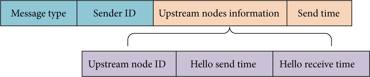
At first, each node sends a HELLO message which contains its own node ID and the local send time. The HELLO message format in our algorithm is illustrated in Figure 2. The message header contains message type and sender ID. When a node receives a HELLO message, it first parses out sender ID added to the upstream node table.

HELLO message format.
If a node cannot receive new HELLO message within a set time
Ranging message format.
Figures 4 and 5 show the HELLO message processing process and ranging message processing process, respectively. Assumed that the node 1 has i upstream nodes, the corresponding HELLO packet send time is

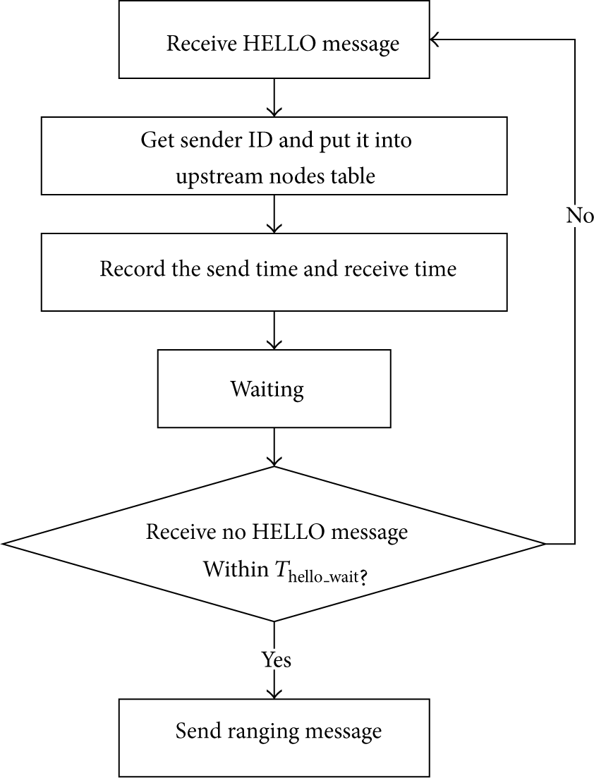
HELLO message processing process.

Ranging message processing process.

Illustration of ranging.
After the link detection stage, each node knows its own upstream node table and downstream node table and knows that the length of the symmetric links corresponds to the downstream node table. We get the length of all symmetric links by two-way TOA ranging in the link detection stage and the node stores the corresponding link length information. Compared with traditional two-way ranging TOA based methods, link detection stage can avoid repeated measurements on the same link and can avoid same node response for many times.
3.3. Anchor Node Directly Localization Stage
In traditional two-way ranging TOA based localization algorithm, ordinary nodes need to send a localization request and the anchor nodes need to send their own coordinates information after they receive each localization request packet that consumes a lot of energy. Since we introduced the link detection stage as a basis, the anchor nodes only need to send their own coordinates information one time after the link detection stage so that the ordinary nodes do not need to send a localization request and the anchor nodes do not need to send the coordinates information repeatedly. The coordinates message format in our algorithm is illustrated in Figure 7.

Coordinates message format.
We take the projection localization mechanism. Depth information of the node can be obtained by the pressure sensor. As shown in Figure 8, node 1 is required to locate; its coordinates are

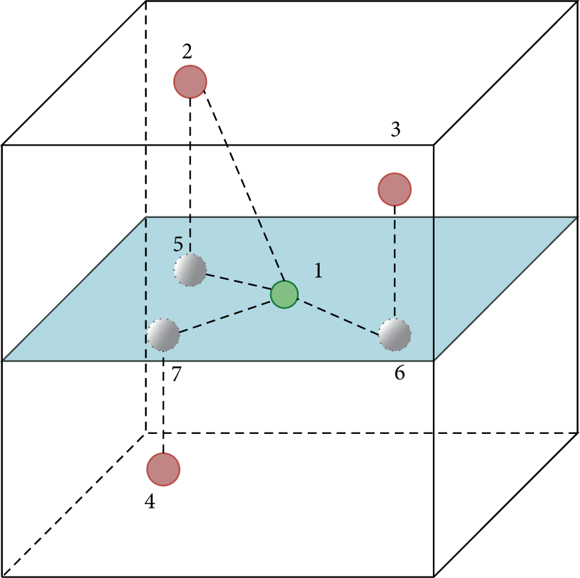
Illustration of projection localization mechanism.
Each ordinary node is equipped with a localization list which is used to store a list of coordinates and link lengths. Ordinary node checks whether the sender ID is in the downstream nodes table after it receives the coordinates message. If the sender ID is in the downstream nodes table, the link is symmetric and we add the coordinates with the link length to the localization list. When there are three anchor nodes in the localization list and the projection nodes of the three anchor nodes are not collinear, the node can be located. Assume that the coordinates of the three anchor nodes are
Anchor Node Directly Localization Stage, the ordinary nodes which can be directly located by anchor nodes get their own coordinates. And some other unlocated ordinary nodes also have some location information in the localization list waiting for supplementation.
3.4. Iterative Localization Stage
In this stage, we use the located ordinary nodes to help locate the unlocated ordinary nodes to improve the localization coverage. Each ordinary node in the anchor node direct localization stage also sends a coordinates message after it get its own location. Unlocated ordinary nodes can supplement their own localization list after they receive these coordinates messages. When the localization list meets the localization criteria, the node can calculate its own coordinates and then can send a coordinates message for the next iteration. In the iterative localization stage we also use the results of link detection stage as a basis; the unlocated ordinary nodes do not need to send a localization request and the located ordinary nodes do not need to send the coordinates information repeatedly. Figure 9 shows the iterative localization stage processing process.

Iterative localization stage processing process.
After the iterative localization stage, most of the ordinary nodes complete localization. And most of the rest of the unlocated ordinary nodes have some location information in the localization list waiting for supplementation.
3.5. Supplementary Localization Stage
After completion of the three stages, the network also has some unlocated ordinary nodes; we can divide them into three cases. The first is the node which has less than three upstream nodes; so the nodes cannot get enough coordinates information for localization. The second is the node which has no symmetry link; so the nodes are unable to get link length when there is no time synchronization. The third is the node which has less than three symmetry links; so the nodes cannot get enough link length information for localization. We propose a loop-assisted localization method to solve the problem of asymmetric link ranging without time synchronization and we let the ordinary nodes get the coordinates and the link lengths of the neighbor nodes which are linked with asymmetric links.
The ordinary nodes in the network which are still not located within

Loop ranging request message format.
The purpose of the loop ranging request message is to solve the problem of asymmetric link ranging without time synchronization. We can find a loop that contains its own by send the loop ranging request message. If the length of all the links in the loop can be known, except the asymmetric link, then we can complete the asymmetric link ranging through the loop. But the known length links need to meet any one of the following two conditions: the link is a symmetrical link or the nodes are located at both ends of the link.
After the node receives the loop ranging request message it needs to modify the loop ranging request message. If the link between this node and the source node is a symmetric link, we change the message to an upstream loop ranging message. If the link between the one-hop node and the source node is an asymmetric link and the node is a located node, we change the message to a downstream loop ranging message. Figures 11 and 12 show the upstream loop ranging message format and downstream loop ranging message format, respectively. Sender information refers to information of the latest relay node; the sender information includes the latest relay node ID and it also includes the coordinates information of the latest relay node if it has been located. In the upstream loop ranging message, the destination ID is the upstream nodes with asymmetric link in the loop ranging request message. In the downstream loop ranging message, the destination ID is the downstream nodes in the loop ranging request message. Relay information includes relay node ID, link length, and message processing time. And the one-hop node coordinate is the coordinate of the node which sends the downstream loop ranging message. So the one-hop nodes linked with symmetrical links can continue to find a loop and complete the distance measurement of the asymmetric links which connect the upstream nodes; the one-hop nodes linked with asymmetrical links also find a loop to complete the distance measurement of the asymmetric links which connect the downstream nodes and send their own coordinates to the source node. Upstream loop ranging message and downstream loop ranging message are collectively referred to as loop ranging message.
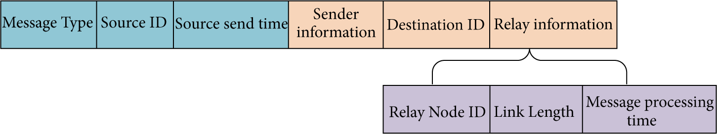
Upstream loop ranging message format.
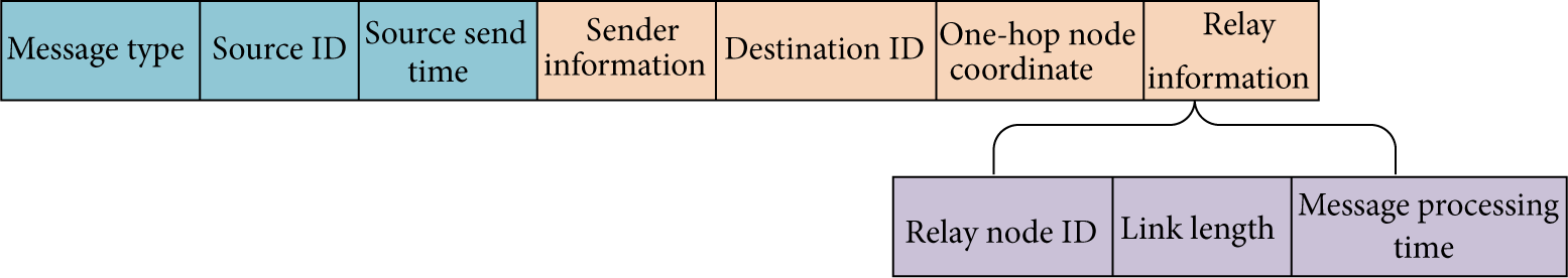
Downstream loop ranging message format.
In the subsequent process, after the node receives the loop ranging message it first judges whether the downstream nodes table includes the node ID in the sender information. If it is not included, we continue to judge whether the sender and the node itself are both located. If this also is not satisfied, the node will discard the message. The length of the link between the two nodes can be known if anyone of the above two judgments is satisfied. Then the node judges whether the destination ID includes its own ID. If it does not include it, the node will update relay information and sender information and will forward the message. Otherwise, the node continues to determine the type of message. The node will send a response message if the message is the downstream loop ranging message. The response message format in our algorithm is illustrated in Figure 13. In this case the coordinates in the response message are the one-hop node coordinates in the downstream loop ranging message. If the message is the upstream loop ranging message, the located node will send a response message directly and the unlocated node will send the response message after it has been located. In this case the coordinates in the response message are the coordinates of the node which send the response message. After the source node receives the response message, the node can calculate the unknown length of the asymmetric link through the total delay and the known length of the links in the loop. The source node also can get the coordinates of the node which are connected with the corresponding asymmetric link.

Response message format.
As shown in Figures 14 and 15, assume that node 1 is an unlocated ordinary node and node 2 and node 3 together with node 1 constitute a loop. The two figures show that node 1 can get the coordinates of the upstream node (node 3 in Figure 14) and the downstream node (node 2 in Figure 15) which are connected with the asymmetric link through the loop. And node 1 also can calculate the length of the corresponding asymmetric link through the loop-assisted localization method.

Illustration of loop-assisted method (upstream node ranging).

Illustration of loop-assisted method (downstream node ranging).
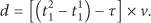
As shown in Figure 16, node 1 sends a loop ranging request message, node 2 is a one-hop node and it will modify the loop ranging request message and will send the upstream loop ranging message or downstream loop ranging message, and node 3 sends a response message; the total length of the known length links in the loop is D, so
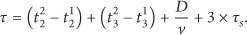
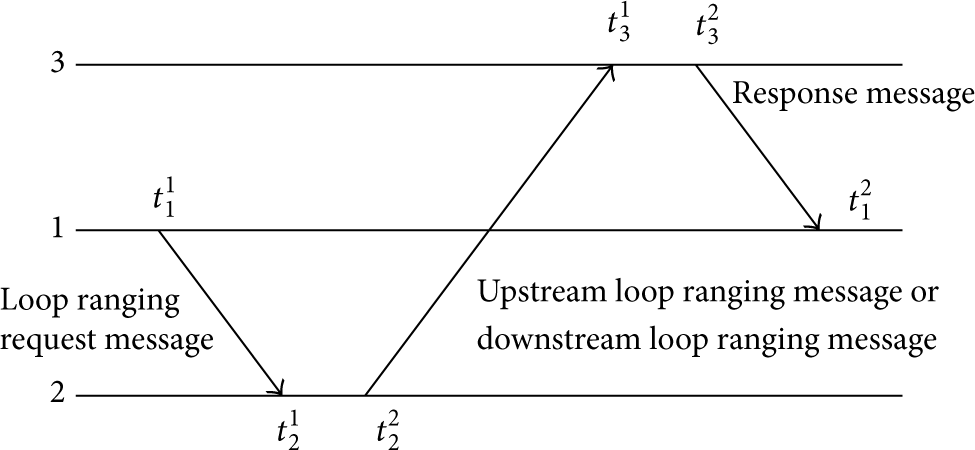
Illustration of message sequence.
As shown in Figure 17, when there are more than three nodes in the loop, assume that there are i relay nodes in the loop except node 1. The receive time and send time of each relay node are


Illustration of more than three nodes in the loop.
At last, node 1 can calculate the unknown length of the asymmetric link; the formula is
To prevent excessive diffusion of the loop ranging message, we introduce the hop counter and stop the spread of the loop ranging message when the value of the hop count is greater than a certain threshold. Corresponding processing processes are shown in Figures 18 and 19.

Loop ranging request message processing process.

Loop ranging message processing process.
After this stage, some unlocated ordinary nodes can get the coordinates of the nodes connected with the asymmetric link together with the length of the asymmetric link. The localization list of these nodes is supplemented and some of the nodes can be located. The ordinary nodes which are located in this stage also send coordinates messages after they get their own location. This will lead a new Iterative process to locate more ordinary nodes. So the supplementary localization stage can improve the localization coverage.
3.6. Intersections Based Location Estimation Mechanism
In practical measurement, error cannot be avoided. The three circles in which the circle center is the reference node and the radius is the length of the corresponding link often cannot intersect at only one point. In other words the calculated coordinates of the node are not unique. For this case, the traditional method uses the least square method to estimate the coordinates, but it does not achieve a high accuracy. We propose an intersections based location estimation mechanism to calculate the coordinates of the unknown ordinary nodes. In practical measurement, the number of intersections among the three circles may be between 0 and 6. Our solution is as follows. When the three circles do not intersect at only a point, first select three points from a triangle, and then take the centroid of the triangle as the location of the unknown node. Otherwise, we take the coordinates of the intersection as the location of unknown node. Figure 20 shows how the intersections based location estimation mechanism selects points and locates the nodes in all the possible cases. How to select three points from a triangle becomes a problem to be solved. When the two circles intersect or the two circles tangent, we select the intersections or the point of tangency. When the two circles have no intersection, we select the percentage point between the two circles center. As shown in Figure 21, assume that the coordinates of the two circles center are
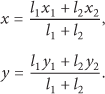

Illustration of all the possible error cases.
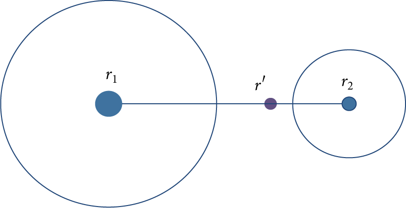
Illustration of percentage point.
4. Simulation Results
4.1. Simulation Settings
We evaluate the performance of the proposed work by using a network simulator written by C++. In our simulations, sensor nodes are randomly deployed in a 300 m × 300 m × 300 m 3D area. Multiple anchor nodes are deployed at the center of the water surface; we assume all the nodes are stationary once deployed. And the ratio of the number of anchor nodes are in between 3% and 12% and our value is 9 anchor nodes. Each sensor node has a random orientation and a beam width which can be set in the simulation. The communication range for both the sensors nodes and the anchor nodes is 100 m; the bit rate is 6600 bps; and the power consumption in sending and receiving are 2 w and 0.8 w, respectively. Each ranging message, loop ranging request message, loop ranging message, and response message was 32 bytes long. For each HELLO message, coordinates message was 16 bytes long. In the simulations, the length of useful information in a packet is not exactly equal to the set size of the packet, but it is definitely not bigger than the set size of the packet. When the length of useful information is less than the set size of the packet, we added FF at the tail of the packet until it matched the set size. In terms of measurement error, we take 0.1% of the distance as the standard deviation: δ; practical value of error obeys the normal distribution:
4.2. Comparison with Existing Algorithm
The biggest advantage of our algorithm compared with other time synchronization needed algorithms is avoiding the time synchronization.
In existing algorithms, most algorithms using TDOA based algorithms and range-free algorithms to avoid time synchronization; only the AAL use two-way range TOA. But AAL is totally dependent on the AUV to complete the localization, so it has great limitation and is not suitable for comparison. Range-free algorithms are coarse-grained and are difficult to meet the needs of the application, and most of them complete the localization with the aid of AUV, so range-free algorithms have great limitation and are not suitable for comparison. TDOA-based algorithms such as UPS are unsuitable to be applied to large-scale underwater networks; this kind of algorithms is suitable to compere the applicable network range but is not suitable to carry out a comprehensive comparative. We choose the LSL algorithm for comparison, LSL is suitable for the large-scale underwater network and has a good performance. In the simulations, we replace the ranging manner of LSL to two-way TOA ranging; then the modified algorithm is called traditional two-way ranging TOA localization algorithm in this paper and it can avoid the time synchronization. So we compare the proposed LASL algorithm with UPS to verify that the algorithm is suitable for the large-scale underwater network and then we carry out a comprehensive comparison between the proposed LASL algorithm and the traditional two-way ranging TOA localization algorithm.
Figure 22 shows the comparison of localization ratio for LASL and UPS algorithm. In the simulation we increase the number of anchor nodes in the traditional UPS algorithm from 4 to 9. This will improve the coverage area of the UPS. It can be seen that the LASL significantly outperforms UPS algorithm in terms of localization ratio. The UPS cannot localize the nodes that reside outside the enclosed area by anchor nodes and the beam width of the underwater nodes makes less nodes get their own location information, so only a small part of the nodes near the anchor nodes can be located and the localization ratio is very low (About 0.01). Therefore, our algorithm has higher localization coverage. That is because LASL takes advantage of the iterative localization method which makes more nodes get their own location information, so our algorithm is suitable for the large-scale underwater network.

Localization ratios for LASL and UPS.
Figure 23 shows the comparison of localization ratio for LASL and traditional two-way ranging TOA localization algorithm. It can be seen that the LASL significantly outperforms traditional two-way ranging TOA localization algorithm in terms of localization ratio. Therefore, our algorithm has a higher localization coverage. That is because LASL takes advantage of the loop-assisted localization method to obtain the length of the asymmetric links and is used to locate. This makes more nodes get their own location information, which effectively improves the localization ratio.

Localization ratios for LASL and traditional two-way ranging TOA localization algorithm.
Figure 24 shows the comparison of energy consumption for LASL and traditional two-way ranging TOA localization algorithm. It can be seen that the energy consumption of our algorithm is lower. That is because LASL introduces the link detection stage; compared with traditional two-way ranging TOA algorithm, link detection stage can avoid repeated measurements on the same link and can avoid same node response for many times which effectively reduces the energy consumption.

Energy consumption for LASL and traditional two-way ranging TOA localization algorithm.
Figure 25 shows the comparison of localization error for LASL and traditional two-way ranging TOA localization algorithm. LASL utilizes the intersections based location estimation mechanism while traditional two-way ranging TOA localization algorithm utilizes the least square method. It can be seen that the localization error of our algorithm is lower; our algorithm has higher localization accuracy. That is because LASL introduces the intersections based location estimation mechanism; the mechanism takes fully into account all the circumstances of the error and gives the approximate solution in each case, which is more accurate than the least square method. This achieves a smaller error than the least square method.
Localization errors for LASL and traditional two-way ranging TOA localization algorithm.
5. Experiment Results
We further do some underwater experiments to verify the proposed localization algorithm. Due to the limitation of the underwater equipment, we cannot verify the performance of the algorithm through the arrangement of a large number of nodes, so we only verify the main function of the algorithm. We mainly verify whether the unknown node can successfully obtain the distance to the neighbor nodes and the coordinate information of the neighbor nodes.
5.1. Underwater Node Design
The node mainly includes the underwater acoustic modem module and processor module. The underwater acoustic modem module is responsible for the realization of underwater acoustic communication, the processor module is responsible for the algorithm implementation and the control the data transceiver of the underwater acoustic modem.
As is shown in Figure 26, we choose LinkQuest UWM2000H underwater acoustic modem to construct the node and we choose the low-power ARM9 embedded system control panel as the processor module. We connect the two parts through the cable to construct an underwater node.

Underwater node components.
5.2. Experimental Scheme
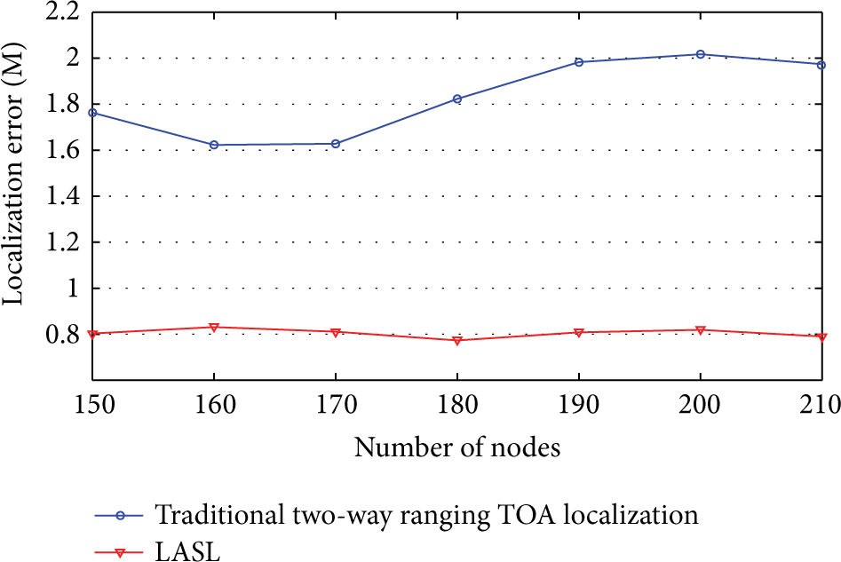
We build the experimental scenario shown in Figure 27. In Wuhan east lake, node 1 is the unknown node; nodes 2, 3, and 4 are anchor nodes which have known coordinates. Double arrows solid line represents the symmetry link; single arrow dotted line represents unsymmetrical link, with the arrow pointing in the direction of asymmetric links.
Experimental scenario.
Figure 28 shows the east lake experiment site layout; we have the four nodes arranged on the four vertices of a rectangle and the size of the rectangle is 30.4 m * 22.6 m. We construct a reference coordinate system in which node 1 (unknown nodes) is the origin. The depth of each node is consistent, which is 1.5 m. We need to detect whether the node 1 can get the coordinate and distance information of the other three nodes (2, 3, and 4).

East lake experiment site layout.
5.3. Experimental Results
Table 1 shows the neighbor nodes coordinates and the distance information obtained by node 1 in the experiment.
Coordinates and the distance information obtained by node 1.

The coordinates of the node 1 calculated through the least square method are −0.406132 m and −1.158879 m and the measurement error is 1.227984 m. The coordinates of the node 1 calculated through the proposed intersections based location estimation mechanism are 0.262461 m and −0.267491 m and the measurement error is 0.374750 m. It can be seen that the proposed intersections based location estimation mechanism can effectively reduce the error. And the experimental results also prove the effectiveness of the proposed loop assisted synchronization-free localization algorithm.
6. Conclusions
A loop assisted synchronization-free localization for UASNs is proposed in this work. Different from other underwater localization algorithms, our protocol takes into account the impact of the beam width and 3D direction of the underwater node on the network topology and we propose a loop-assisted localization method to solve the problem of asymmetric link ranging without time synchronization, that effectively improves the localization ratio. In addition we introduce the link detection stage to avoid repeated measurements on the same link and avoid the same node response for many times. Finally, we propose an intersections based location estimation mechanism for error problem in practical measurement and improve the localization accuracy. The simulation results show that the proposed localization algorithm can achieve excellent performance in terms of the metrics, the localization ratio, energy consumption, and localization accuracy. The experimental results prove the effectiveness of the proposed localization algorithm.
In the future, we would consider the localization algorithm applied to the high dynamic UASNs. The impact of mobile sensors will also be considered in future work to enhance the practicability of UASNs.
Footnotes
Conflict of Interests
The authors declare that there is no conflict of interests regarding the publication of this paper.
Acknowledgments
This paper is supported by “National Program on Key Basic Research Project (973 Program) (Grant no. 2011CB707106)” and National High Technology Research and Development Program (863 Program) (Grant no. 2014AA09A512).