
Abstract
Fiber Bragg Grating (FBG) sensor network has attracted more attention in online condition monitoring for the large mechanical equipment. By the efforts of the encoding scheme for sensor nodes, the capacity for the distributed FBG sensor network can be significantly improved. However, due to the increasing number of sensor nodes, the precision of tracking and locating for the FBG sensors has become a bottleneck that should be conquered. In order to realize more accurate and comprehensive condition monitoring for the large mechanical equipment, an enhanced tracking algorithm for distributed encoding FBG sensor network is presented. The novel tracking algorithm uses three classes of progressive intelligent processing approaches, including the improved cycle matching method, the secondary filter intelligent disposal method, and the assistant decision processes method, to conquer the limitations of the traditional tracking algorithm in which the chaos and error results would be caused as the sensor information variations are overlapped. A set of experiments has been conducted and the results demonstrate that the proposed tracking algorithm performs better than the traditional algorithm in location accuracy for the distributed encoding FBG sensor network and can effectively operate in various working conditions of the large mechanical equipment.
1. Introduction
With the rapid development of modern industrial technology, the condition monitoring and safety management for mechanical equipment, operating in a long-term running, have attracted more attention from academia and industry and also resulted in a significant effect on the national economic development, production safety, and so forth [1, 2]. The traditional electrical sensors cannot meet the need of long-term accurate safety monitoring due to the poor performance in anti-interference, large-scale distributed sensing, and environment adaptability. Moreover, in some cases, due to the large size and weight, it is difficult to be deployed on the critical parts of the equipment. In particular, in the multifield coupling interference or harsh working environment, the traditional electrical sensors are very difficult to perform the long-term condition monitoring of the large mechanical equipment. Distributed FBG sensor network owns the characteristics, for example, intrinsically safe, no power transmission, antielectromagnetic interference, dynamic distributed networking, easy reuse, smart material, flexible installation, long service life, and so forth [3, 4], thus it has unique advantages for the condition monitoring of the mechanical equipment operating in a harsh environment [5]. Furthermore, with the development of Internet of Things (IoT), the FBG sensor network and variety of equipment can access to the Internet by IoT technology to realize equipment condition monitoring and information management in the wide area network (WAN) environment. Meanwhile, FBG sensor network is the extending application of IoT terminal access technology which provides support for information exchange between equipment and human. In IoT, the equipment, human, and environment are all included in the sensor network. Using FBG sensor network and IoT technology, they can enable anyone to communicate with any equipment at any time and any places.
The distributed FBG sensor network cannot only sense the condition information of the mechanical equipment, but also realize the transmission of the sensing data. In such system, the multiple FBG sensors can be deployed on the critical components of the large mechanical equipment to realize the functions, including multipoint condition monitoring, information recognition, and sensing tracking [6]. Moreover, the FBG sensor network can also access to other communication networks to deliver the massive sensing data to the management centre, which can provide the efficient support for the distributed sensing data storage and processing, real-time working condition monitoring, and resource service sharing in the WAN environment. So the sensor network technology and network heterogeneous integration technology are the key to realize IoT of equipment for distributed condition monitoring.
The realization of the FBG distributed sensor network relies on the deployment model of the large-scale sensor nodes as well as the tracking algorithm for sensor node location [7]. Although some existing researches have focused on the FBG sensor network tracking and the network capacity improvement, there is still a bottleneck for the network multiplexing capability, sensing intelligence, and the practical application requirements for the distributed and multiparameter condition monitoring. Therefore, a number of challenges should be considered, including the following.
(i) The FBG Sensor Network Capacity Has Increased Largely. The system performance and the practical application range are determined by the sensor network capacity. However, the existing multiplexing method is restricted by the light source bandwidth and demodulation system tuning range. Even using multiplexing technology, it is also very difficult to increase the number of sensor nodes to a large extent. Therefore, it is an urgent need to conquer the bottleneck of optical fiber sensing theory restriction in a large network capacity, by using a new type of FBG sensor and new multiplexing technology. As the new kind of FBG sensor is used, the corresponding tracking algorithm should also be redesigned. In particular, it should be able to fulfill the requirements of the large FBG sensor network tracking accuracy.
(ii) The Increased Complexity of the Sensing Network Structure Has Resulted in Higher Requirement for the Tracking System. Although the sensor system capacity can be enlarged to some extent by multiplexing hybrid networking method, the system complex, application cost, and control difficulty are also increased as the nodes increment due to the more additional optical devices used in the network. Thus, it is difficult to design appropriate tracking algorithm for multiple sensor nodes network. Particularly in the long distance, distributed, and large capacity environment, it is necessary to design a relatively simple network structure. Meanwhile, the accuracy assurance of sensing network resolution and tracking should also be further considered.
The remainder of the paper is organized as follows. Section 2 describes the related works of the distributed FBG sensor network and the tracking algorithm. The encoding FBG sensor network system structure and operation process is presented in Section 3. Section 4 discusses the enhanced tracking algorithm in detail from three progressive processes. The experiment results and analysis of the proposed tracking algorithm are presented in Section 5. Finally, Section 6 concludes the paper.
2. Related Works
At the end of the 20th century, the optical fiber sensing technique started to be applied in engineering structure safety monitoring field, such as bridge, dam, nuclear power, petrochemical engineering, civil engineering, and mining, and exhibited a wide range of advantages [8, 9]. Especially in the potentially harsh environments, while electric sensors may increase the risk of fire or explosion in some special conditions, such as oil industry, power plants, and chemical factories, they became more attractive [10]. In recent years, researchers have used the FBG sensor technology in the area of large mechanical equipment for dynamic online condition monitoring. USA military used FBG to monitor the ship working condition [11]. FBG sensor network is also applied to monitor the aeroengine and spacecraft health in Canada, Japan, and Israel. In China, it is used for large manufacturing equipment online condition monitoring, such as dumper, large cranes, and aeroengine, which has been achieved in a series of research results [12].
The application of distributed FBG sensor network in these domains can take full advantages of FBG intrinsically safe, no power transmission, antielectromagnetic interference, and long service life to accomplish the functions that the normal electric sensors cannot complete.
In the practical engineering applications, the real-time and comprehensive condition sensing data should be collected by a FBG sensor network, and thus a large number of sensor nodes are needed in such system. In order to satisfy the requirements of the large-scale sensor nodes deployment, different multiplexing network technologies should be used. Furthermore, the appropriate tracking algorithm is also required to analyze the condition sensing data and to facilitate the long-term safety monitoring. For different multiplexing network mode, the tracking algorithm is different.
A number of researches focus on the Wavelength Division Multiplexing (WDM), Time Division Multiplexing (TDM), Space Division Multiplexing (SDM), Frequency Division Multiplexing (FDM), Code Division Multiple Access (CDMA) or other combination mode to realize the FBG multiplexing network and the sensor node tracking. WDM is one of the most intensively investigated and widely used multiplexing schemes in the practical engineering. As early as 1993, the tunable optical fiber F-P filter detection method was used for FBG wavelength division multiplexing [13]. In [14], the FBG sensor network capacity is increased by WDM method and genetic algorithm. The FBGs with different center wavelength are deployed in one optical fiber. The network tracking is realized according to the characters that the FBGs wavelength reflection peaks have their own wavelength intervals. However, due to the limitation of light source spectral bandwidth and dynamic measurement range, the maximal multiplexing number is less than twenty.
In [15], by M-Z interferometer, the sensor number of FBG TDM sensing system is 4. Then, in [16], the sensor number is increased to 8 by TDM integrated optical wavelength discriminator. In [17], the laser delayer is used in the sensor network. According to the difference of neighboring sensor light reflected time, the experimental result shows that 12 FBG sensor nodes can be successfully resolved by TDM. TDM can conquer the limitations of light source bandwidth and center wavelength dynamic range of WDM, but the laser delayer and impulsator should be added in the FBG network. In addition, in order to reduce the laser power loss, the weak reflection FBG and fiber amplifier also should be used. In such a case, the system cost will be increased and the sampling frequency will be reduced.
In [18], the SDM sensor system is built by 4 FBG sensors in one optical fiber. Meanwhile in [19], each independent sensing channel is connected by SDM optical switch to measure the surface vibration dynamically, and the sensor in each channel can work independently. SDM has the advantages of small crosstalk, unstinted frequency bands, and high signal-to-noise ratio. But the optical power utilization rate is low and also restricted by light switch, and the sensor number is less than 10 in one single.
In [20], the real-time multipoint strain sensing system is constructed by FBG subcarrier FDM and optical frequency domain reflection multiplexing technology. The continuous-wave frequency modulation method is used to realize FBG tracking. But the demodulation system is much more complex and the multiplexing sensor number is less than ten.
From the analysis above, although the traditional multiplexing and tracking methods have their own advantages and are suitable for some applications; however, it is difficult to meet the requirement of large capacity and distributed sensor network application. Therefore, a variety of mixed multiplexing and tracking methods have been proposed to enhance the number of multiplexing sensor nodes.
In [21], the SDM/WDM hybrid network mode is used. The sensor nodes number including three optical channels is increased to 66 and the signal to noise ratio is also improved. But it is limited by the wavelength interval and light source bandwidth itself. The FBG sensor network intrusion prevention system based on TDM/WDM multiplexing technology is shown in [22]. In [23], the FBG sensor network tracking is realized by FDM/WDM combination method. By this way, the number of sensor nodes can be more than one hundred and the light frequency and wavelength information can be fully utilized. But the demodulation system is very complex and also restricted by the optical power. In [24], the SDM/TDM/WDM hybrid network is used. It can take the advantages of high reliability of parallel topology, excellent performance of anti-interference, and high utilization of serial resource. Also in [25, 26], the mixed multiplexing network mode is used. But the system construction cost is very high and the system structure is very complex which is hard to control.
In addition, some new FBG sensing and tracking technologies have also been proposed to increase the sensor system capacity with the limitation of light source bandwidth. In [27], the CDMA technology is applied to measure the high speed stress-strain signal in the FBG sensor network. The pulse modulated by pseudorandom sequence is used as light source, and tracking is realized by independent correlation algorithm. It has the high performance of anti-interference and multiplexing capability. The number of sensor nodes can be more than one hundred. However, the selection requirements of pseudorandom code and light source are relatively high. Moreover, the light detection equipment and the whole FBG sensor system are much more complex.
The encoding FBG sensor network and its multiplexing theory are shown in [28]. Encoding FBG is a kind of new sensor source which is made by carving two or more different center wavelength gratings on the same position of one fiber. In the sensor network, the encoding FBG node with different center wavelengths will function together to respond to the outside condition changes, such as temperature, stress-strain, and vibration. It is tracked according to the character that the shifts of central wavelengths on various FBG sensors in one node have the same responses to the change outside. The network capacity is decided by the different wavelength coding permutations. The total sensor number can be more than hundreds in a single channel.
The encoding FBG distributed sensor network has the advantages of simple network structure, large network capacity, and fast tracking speed which can improve the network application practicability greatly. It can also work with TDM, SDM, and FBG network together in which the encoding FBG sensor network can be used as one of the time unit subnets of TDM network or space channel sets of SDM network. In this kind of mixed network mode, the whole network capacity is increased further.
At the extension of FBG sensor network capacity, sensor node accurate tracking algorithm plays an important role. For the encoding FBG sensor network, in the conventional approach, if the wavelength variations from different demodulations are overlapped, this will lead to wrong tracking results. Even the whole sensor network will be a total failure. In order to resolve this tracking problem, the traditional direct cycle matching method is improved and a new three-class tracking algorithm is proposed. Even there are a lot of overlapped sensing variations; the enhanced tracking algorithm can work efficiently.
In recent years, researchers have done a lot of works that involved distributed FBG sensor networking method and tracking mechanism, but not only from the point of theory but also from view of application, and there are still many shortcomings. Also, lots of new problems have to be resolved on the performance improvement and system application. So, it is necessary to study on the distributed FBG sensor networking method and tracking algorithm. Especially, the tracking algorithm is very important for the distributed encoding FBG sensor network. The following sections illustrate the enhanced tracking algorithm in detail.
3. System Architecture
FBG is a sensing element that measures strain, temperature, or both which can be connected in series to form FBG sensor network. Encoding FBG is a new kind of FBG with the characters of coding multiplexing. In the network, each FBG sensor is called sensor node which is deployed on the critical components of mechanical equipment to monitor the real time temperature (degree) or stress-strain (microstrain/K) that can be calculated by the wavelength shift (picometer, pm). The purpose of the tracking algorithm is to determine the corresponding relation between the wavelength shift and the sensor node, in other words, the relation between the measurement parameters and the critical components condition of the equipment.
The encoding FBG is made by carving two or more than two different center wavelength grating on the same position of one fiber. According to the characters of encoding FBG, the multidimensional coding technology is used in the system. For example, 1 Celsius degree temperature difference will cause 1 pm wavelength shift. If there is a two-dimensional encoding sensor node with two different center wavelengths 1280 pm and 1290 pm, when the temperature increases two Celsius degree, this encoding FBG's wavelengths will be 1282 pm and 1292 pm. The two different center wavelength FBGs belong to the same encoding FBG node. That means the wavelength that shifts from the same FBG node will remain the same. Every FBG center wavelength is encoded. Multiple code permutation is used to represent the FBG sensor node.
In distributed FBG sensor network, 1550 nm and 1300 nm center wavelength FBGs are the most frequently used types. Assuming that the bandwidth of the broadband light source is 30 nm and the FBG spectrum width is 2 nm, the maximum multiplex nodes are

If the selectable center wavelength numbers of two-dimensional encoding FBG are m and n, the total count of the multiplex nodes is

The system structure of two dimensional encoding distributed FBG sensor network is shown in Figure 1.

System structure of encoding distributed FBG sensor network.
4. Enhanced Tracking Algorithm
The target of FBG sensor network is to obtain the corresponding wavelength shifts of sensor nodes which are deployed on the critical components by special tracking algorithm to monitor the operation condition for mechanical equipment. Therefore, the tracking algorithm plays an important role in the distributed sensor network. It is implemented in the upper computer that usually can make full use of PC or server hardware computing ability to meet the requirements of tracking speed and accuracy for the large-scale distributed sensor network.
4.1. Related Definitions
(1) Wavelength Encoding Definition. For two-dimensional encoding FBG sensor network, the reflection wavelength information which is demodulated by the corresponding FBG demodulator will be divided into two groups. Data in the first group is from the demodulator of the first dimensional encoding FBG. Data of the second group is from the second demodulator. Define the center wavelength ID of the first dimensional encoding FBG as (
(2) Result Element Definition. The element of the result set defines as
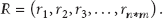
(3) Tracking Result Set Definition. Tracking result is defined as formula (3). In it, r is the result element defined above. It includes all the encoding FBG ID and the corresponding wavelength shift. From this matrix, the sensor nodes can be tracked. For example,
4.2. Algorithm Implementation
The algorithm mainly consists of three process classes to realize the tracking of distributed encoding FBG sensor network step by step. In each class, if it conforms to the termination conditions, the algorithm will terminate directly and will not continue to enter the next class process. Through this way, both the algorithm efficiency and accuracy can be guaranteed. The first class focuses on the sensing information that there are no overlapped wavelength variations. Also, the traditional tracking algorithm is improved by adding matching constraint conditions to ensure the algorithm accuracy. When the wavelength variations are partial or extensively overlapped, the algorithm will enter the second or the third class tracking processes where the sensing information will be processed by secondary filter or assistant decision methods until the correct tracking matrix can be obtained.
(1) First Class: Fast Matching Tracking. When the received sensing information wavelength variations are not overlapped, the tracking process can be completed in this class. On the basis of traditional tracking algorithm, the unique matching condition is included to improve the tracking accuracy. The main steps are as follows.
Step 1 (grouping preprocessing).
In each demodulation channel, the received wavelengths will be sorted by quick sort method and divided into several groups according to the number of center wavelengths. For the two-dimensional encoding distributed FBG sensor network, supposing that the multiplexed wavelength numbers are m and n, so the node total amount is
Step 2 (wavelength encoding).
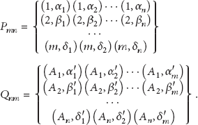
According to the predefinition of wavelength encoding, the different center wavelength sensors will be encoded like (wavelength ID, wavelength shift). The encoding matrixes are shown in formula (4). In it,
Step 3 (cycle matching).
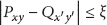
The traditional algorithm process for the two-dimensional encoding sensor network is like this, one element from the first matrix P and another one from the second matrix Q are taken to match with each other directly. If the first element wavelength shift from P is equal to the second element from Q, they are considered to be the same FBG node. Then it is a successful tracking result and can be marked as r = ((First FBG ID, Second FBG ID), wavelength shift). But if there are overlapped wavelength shifts, it cannot get the right result. So, the constraints are added as formulas (5), (6) to improve the traditional algorithm. If the elements P and Q meet the requirements of formulas (5) and (6), it means that the matching is successful. Formula (5) means the wavelength shifts difference between P and Q is less than or equal to the threshold. It is the basic tracking theory of encoding FBG sensor network. Due to the influence of systematic error, the encoding FBG shifts from the same sensor node will not be strictly equal. So, it can be considered correct tracking as long as the difference is close to a minimum. Formula (6) means that there are not any other duplicate equal shifts in the line where it is except Q itself. By this way, it can ensure the uniqueness and correctness of the matching results. If both of the restrictive conditions are true, it means that it is the only tracking result. Define R for result matrix and C for temporary matrix. The initial values of R are (possible matching IDs, 0) and C is empty. After the whole successful tracking process is completed, R will store the right matching results and C will return empty. Each time, the sensor node ID and its corresponding wavelength shift will be updated in R and the temporary matching result will be recorded in C. The wavelength shift of the correct tracking sensor is

Step 4.
Repeat Step 3 until all of the elements have been traversed. After this, if the encoding matrixes P and Q are empty in the end, it means that there are no uncertain values and the matrix R is the final tracking result. Temporary matrix C can be deleted. The tracking algorithm does not have to enter the next class processing. But if P or Q is not empty, that means there are overlapped wavelength shifts. Duplicate matrix
(2) Second Class: Secondary Filter. when the received wavelength sensor information shifts are overlapped and cannot be tracked uniquely in the first class process; this will be processed further in this step.
Step 5 (residual matrix).
Removing the successful tracking result nodes set C from M, the no-tracking nodes set; that is, the residual matrix can be obtained. Also the successfully tracking elements are deleted from P and Q. In the remaining unmatchable elements set, the equal wavelength shifts are considered as standard to rebuild the no-tracking group collections

Step 6 (secondary filter).
Take one no-tracking element ID(
(3) Third Class: Assistant Decision. After processing by secondary filter, the remaining FBG sensing information will be processed in this class. In general, the sensing information will not be highly overlapped. So through the above steps, it can be usually tracked successfully. But in some special working conditions, maybe there is a lot of overlapped sensing information. That means that many sensor nodes’ wavelength shifts in the sensor network are equal. For this kind of extreme case, it needs to repeat the assistant decision and secondary matching process until the final accurate tracking results are obtained. Here, the assistant decision matrix R mentioned above will be used.
Step 7 (assistant decision).
After Step 6, the rest of the sensing information cannot be uniquely determined. Here, we consider that the sensing condition will not be a sudden change. So, the no-matching element will be selected and compared with the corresponding element in the assistant decision matrix R. The sensor coding with the smallest change can accepted as the matching result, as formula (8) is shown. If all the wavelength shifts in R are equal, we can get the first one. At the same time, the assistant decision matrix R will be updated by the new result and the successfully tracked elements will be deleted from

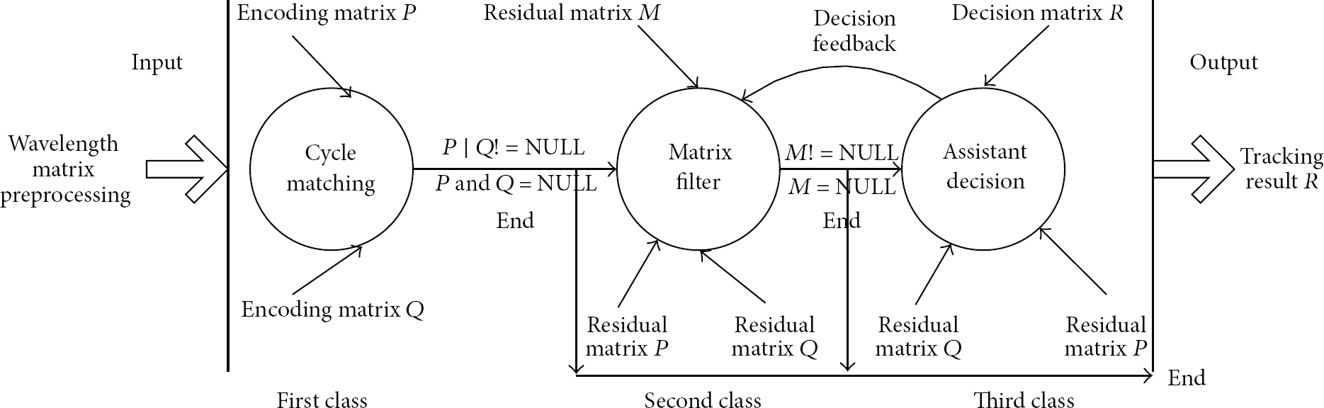
Encoding FBG sensor network tracking algorithm.
5. Algorithm Analyses and Verification
5.1. Algorithm Accuracy Analysis
The direct cycle matching method is used in the conventional algorithm for encoding FBG sensor network to realize sensor nodes tracking. It fits to the simple FBG network with a small number of sensor nodes. But in the large scale sensor network, the wavelength shifts may be overlapped sometimes due to the massive sensing information. By the traditional tracking algorithm; for example, the first encoding sensor wavelength group is (1, 2, 3) and the second one is (

The confusing tracking result.
Therefore, in the first class, in addition to the constraint of equal wavelength variations matching, as formula (5), the other wavelength variations also should be considered, as formula (6). For example, when
When there are overlapped wavelength variations, it cannot make the decision immediately. The secondary filter method can be used to obtain the possible unique tracking information further. For example, through the first class processing, there are two encoding sensor groups (1, 1, 2, 3) and
After the secondary filter processing in the second class, if there is also uncertain information, the assistant decision matrix R will be used to compare with the tracking result for decision support. So, the tracking accuracy will be further enhanced.
From the above analysis, the algorithm accuracy is guaranteed by the progressive three classes processing. Moreover, the tracking algorithm effectiveness will be discussed from three different conditions in detail below: no wavelength variations overlap, partial wavelength variations overlap, and high wavelength variations overlap.
(1) No Overlapped Sensor Information Variation. In this case, the tracking can be completed in the first class quickly and no need to enter the other two processes. Suppose that the original center wavelengths are (1280, 1290) and (1380, 1390, 1400). From the different two channels of demodulators, we get the wavelength groups as follows:
After the traditional method and enhanced tracking algorithm processing, respectively, the same results are obtained as shown in Figure 4. It means that if the wavelength information is not overlapped, the sensor nodes can be tracked effectively by both of the traditional and enhanced tracking algorithms.

Tracking result with no overlapped wavelength shift.
(2) Partial Overlapped Sensor Information Variation. Partial overlapped information means some wavelength shifts are not overlapped which can be tracked directly and some others cannot be tracked by the traditional tracking algorithm. Suppose that the FBG center wavelength groups are (1280, 1290, 1300) and (1380, 1390, 1400). The numbers of sensor nodes are

From the above two groups, we can see that there are some overlapped wavelength shifts like 0.5 and 1. Supposing that the central wavelength coding are (1, 2, 3) and

By the traditional direct cycling tracking algorithm processing, the result is shown in Figure 5. The first matching element of

Tracking result with partial overlapped wavelength shifts.
With enhanced tracking algorithm in Step 3, only the matching results

The generation process of remaining matrix M is shown as the flowing expression. It means that the successful tracking elements in the first classes (

From


Algorithm processing sequence.
From the analysis above, even if there are overlapped wavelength shifts, the unique tracking results by the enhanced algorithm can be obtained which is shown in Figure 7.

Partial overlapped tracking result by enhanced algorithm.
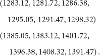
(3) High Overlapped Sensor Information Variation. It is the extreme case when the sensor information variations are highly overlapped. It means that the sensor information cannot be tracked successfully only by the matching mechanism which needs to add other criterion to complish the network nodes tracking. For example, the received wavelength information groups are

From that, there are many overlapped wavelength shifts that we called it highly overlapped. After preprocessing, encoding and Step 3, none of them can be matched successfully. Because there are just two kinds of wavelength shifts 0.5 and 1, also none of them can match uniquely. Using the traditional algorithm, the tracking result is shown in Figure 8.
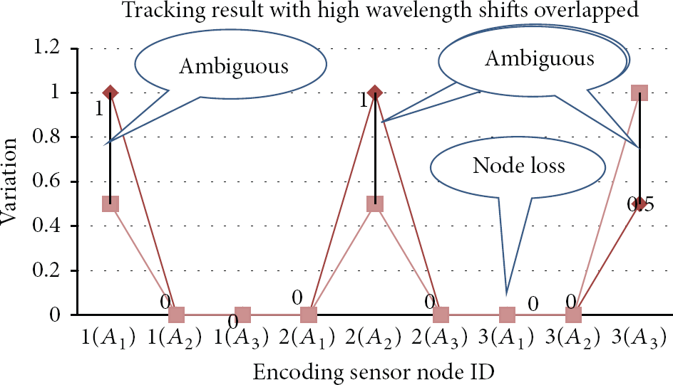
High overlapped tracking result with traditional algorithm.
In the figure, none of the nine nodes can be tracked successfully. There are many ambiguous sensor nodes such as (1
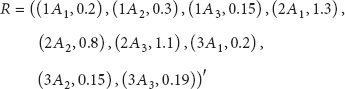
After Steps 4 and 5, the residual matrixes P and Q and assistant decision matrix R are shown as formulas (16), (17), and (18). For example, taking (


Tracking the algorithm solving process, after three times assistant decision of Step 7 and two times cycle solution of Step 6, the tracking result can be obtained even in the extreme environment which is shown in Figure 9.
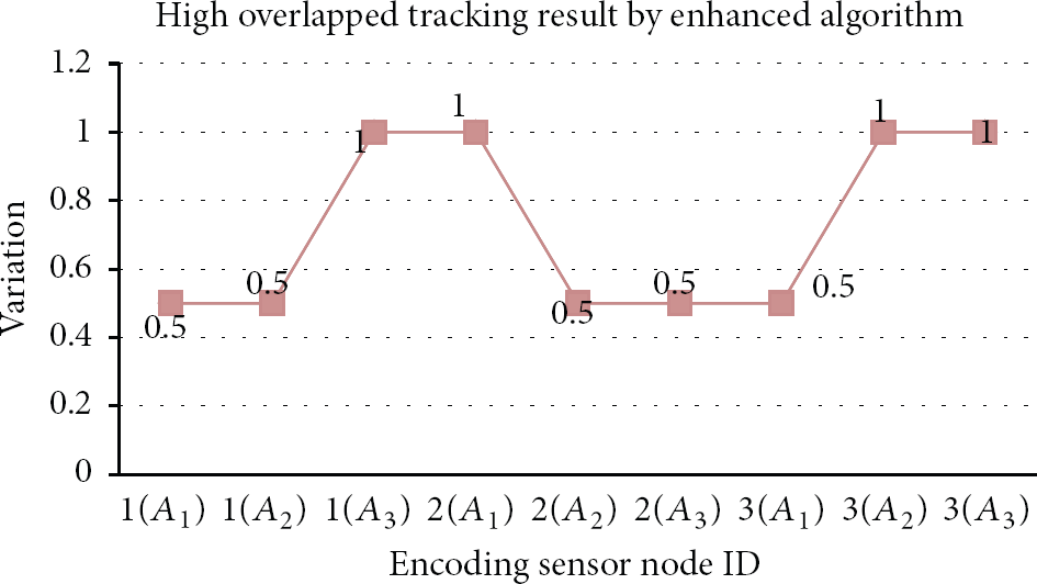
High overlapped tracking result with enhanced algorithm.
Also, we will test the algorithm in the large-scale nodes environment further. Suppose that there are 15 kinds of center wavelengths with 2 nm wavelength interval in the two dimensional encoding FBG sensor network, the total number of sensor nodes is
The tracking results analysis of traditional algorithm.


Tracking result by the enhanced algorithm.
Also, the traditional tracking method result is analyzed in Table 2. In the table, loss rate is the ratio of no-tracking result sensor number and the total sensor number. The ambiguity rate is the ratio of ambiguity sensor number and the total sensor number. From the table, as the increment of overlapped ratio, the loss rate and ambiguity rate will increase rapidly. So, the accurate tracking result cannot be obtained by traditional algorithm.
Comparing results between traditional algorithm and enhanced algorithm.

5.2. Algorithm Efficiency Analysis
When the data size of sensor information is small, there is little relationship between algorithm efficiency and data size benefited from the modern computer high processing performance. So, in this case, the algorithm validity should be considered first. With the increase of sensor nodes number, especially in the massive sensor information environment, the tracking instantaneity will be affected by the algorithm efficiency directly. When there are no overlapped wavelength shifts, the efficiency of traditional algorithm and enhanced algorithm is almost the same by quick sort and group segmentation processing. In the case of massive information overlapped, algorithm efficiency will decrease slightly due to the other two processes, the secondary filter, and assistant decision.
In Step 1 of the first class, the quit sort algorithm average efficiency is 
The relationship between different sensor nodes and the consuming time is shown in Figure 11. The testing hardware platform is PC, CPU i5-2500 3.3 GHz, RAM 2.0 GB, Windows 7 32 bit. In the figure 11 we can see, with the increase of sensor nodes number, that the time consuming will increase and the algorithm efficiency will decline gradually. In practice, the actual consuming time also associates with the demodulation rate and computer hardware performance. From the figure 11 if the number of sensor nodes is less than 800, the consuming time is near 0. With the increasing amount of sensor node, consuming time will be longer and longer. Especially, when the node number is more than 17000, the tracking time will come close to one second. In the actual work, if the sample frequency is 1 HZ, the sensor network can accommodate 15000 sensor nodes. Also, the data size is determined by the optical fiber demodulator frequency which is relevant to the tracking efficiency. From the figure, if the optical fiber demodulator frequency is 100 Hz, about 170 sensor nodes can work simultaneously. So, the algorithm efficiency can meet the requirement of massive sensor nodes in the FBG sensor network.
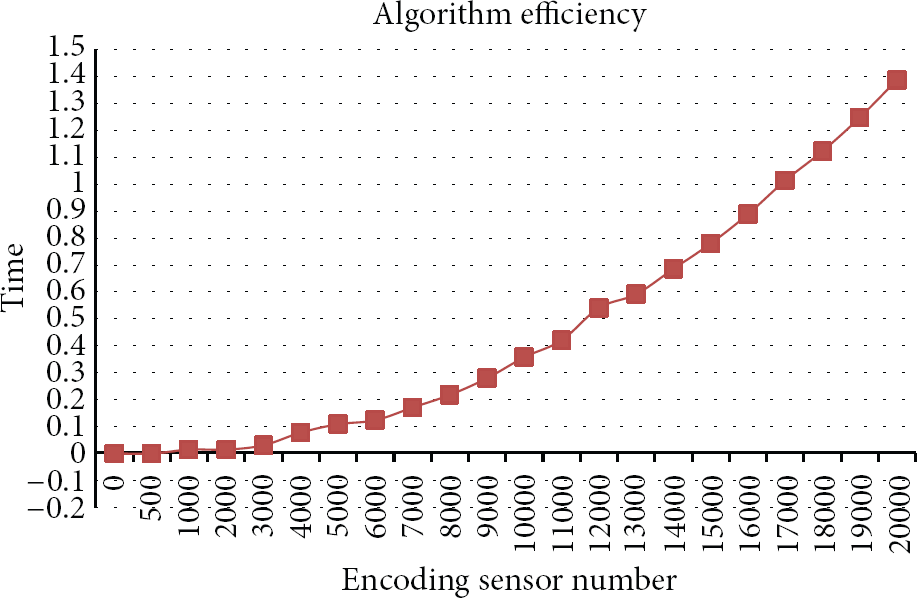
Relationship between the number of sensor node and efficiency.
6. Conclusions
The distributed sensor network based on encoding FBG has an important significance for condition monitoring of large mechanical equipment, and the efficient deployment of the large-scale and distributed FBG sensors is the way to realize the comprehensive and accurate condition monitoring in practical engineering applications. The encoding FBG sensor is an effective approach to facilitate the large-scale deployment of the sensor nodes and to improve the network capacity, and the tracking algorithm for the FBG sensors is a most important issue for the successful implementation of such system, due to the fact that it is the deciding factor for determining the sensor network accuracy. For the traditional algorithms, the tracking ambiguity and node loss phenomenon can come out, as there are overlapped wavelength shift FBGs. Therefore, in order to conquer the disadvantages of traditional encoding FBG network tracking algorithm, an enhanced tracking algorithm, using three classes of progressive processing approaches, for the encoding of FBG sensor network is proposed. The improved cycle matching method, secondary filter, and assistant decision method are used in each class, in order to avoid error tracking results caused by the FBG sensor wavelength shift overlapped. Using the enhanced algorithm, it can effectively track the large-scale FBG sensor nodes in the distributed network even with overlapped FBGs. Meanwhile, the tracking accuracy and efficiency can also be guaranteed. Theoretical analysis and simulation experiments demonstrate the practicality and effectiveness of the developed tracking algorithm. The improved tracking algorithm lays the foundation for the distributed FBG network with massive capacity in the practical applications of condition monitoring for large mechanical equipment.
Footnotes
Conflict of Interests
The authors declare that there is no conflict of interests regarding the publication of this paper.
Acknowledgments
This research is supported by the Specialized Research Fund for the Doctoral Program of Higher Education of China (Grant no. 20120143110017), the National Natural Science Foundation of China (Grant nos. 50935005 and 51175389), and the Keygrant Project of Chinese Ministry of Education (Grant no. 313042).