
Abstract
In order to study the cavitation area of the Upstream Pumping Mechanical Seal, three-dimensional microgap inner flow field of the Upstream Pumping Mechanical Seal was simulated with multiphase flow cavitation model and dynamic mesh technique based on hydrodynamic lubrication theory. Furthermore, the simulated result was compared with the experimental data. The results show that the simulated result with the Zwart-Gerber-Belamri cavitation model was much closer to the experimental data. The area of cavitation inception mainly occurred at the concave side of the spiral groove and surrounding region without spiral grooves, which was nearly covered by the inner diameter to roots of grooves; in addition, the region near the surface of the stationary ring was primary cavitation location. The area of cavitation has little relationship with the medium pressure; however, it became larger following increasing rotating speed in the range of researched operating conditions. Moreover the boundary of cavitated area was transformed from smooth to rough, which occurred in similar film thickness. When cavitation number was decreasing, which was conducive to improving the lubrication performance of sealed auxiliary, it made the sealing stability decline.
1. Introduction
Mechanical seal has been applied widely in the petrochemical industry, nuclear power plant, and aviation with excellent sealing performance, more reliability and longer service life. The structure of a mechanical seal was shown in Figure 1, which includes stationary ring, rotating ring, and other auxiliary seals. Ever since noncontacting face seal was explored, Upstream Pumping Mechanical Seal has been the focus of research due to spiral grooves processing seal faces that can retain a continuous fluid film to make seal faces separate, which result in less wear and less leakage rate. However, under conditions of high fluid pressures and high speeds, fluid film between seal faces shows cavitation phenomenon resulting from surface micromolding, axial vibration, or surface waviness. Cavitation is the formation of steam bubbles in the low pressure area of the fluid flow field [1], which plays an important role in maintaining the hydrodynamic effect of mechanical seals. The impact of lubrication film cavitation area on hydrodynamic effect, leakage rate, and friction of the mechanical seal was a critical problem that needs further research and more attention.

Schematic diagram of mechanical seal.
The cavitation area indicating that the full film ruptures and reforms in mechanical seal, which has an impact on the fluid flow in the seal faces. A number of studies that investigated the cavitation region of lubrication film in mechanical seals were analyzed. Nakahara [2] demonstrated that the development of the cavitation regions decreased the side leakage. As discussed by Nau [3], notice that the cavitation extended right to the edge of the seal face and was virtually continuous around the circumference. In addition, an analytical solution for the boundary of the film cavitation region was presented. A series of experiments were conducted primarily by Qiu and Khonsari [4, 5], which made the formation of cavitation visualized in a dimple-enhanced seal-like structure. They observed that cavitation was not shown in all the dimples during the experiment and the generation and development of which was highly dependent upon the rotational speed. The difference in the film thickness will have an effect on the generation of cavitation. Yuichiro et al. [6] recorded that the gas-liquid interfaces and the steady fluid flow was maintained along the rows of dimples as the cavitation rings with less friction. Li [7] used an open seal structure to observe the cavitation phenomenon in mechanical seal with line grooves. The cavitation bubble appeared steady in the line grooves. The cavitation region decreased with increasing sealed pressure or film thickness and became larger as the rotating speed was raised. Hu et al. [8] found that the seal dam could prevent cavitation of radial grooved face seals and cavitated area increased with the increment of rotary speed and, on the contrary, cavitated area decreased with the increment of groove depth. Wang et al. [9] observed that the cavitation region was not restricted to the dimples in the two-phase laser surface texturing mechanical face seals. The hydrodynamic effect produced by cavitation increases the load capacity on the end faces so that the gap between the seal faces increased.
From these studies, the seal performance of mechanical seals could be affected by the cavitation regions. How to control the cavitation area and take advantage of them to improve the seal performance is a cavitation research hot topic. Due to the cavitation of mechanical seal involved complex problems, such as microscopic cavitation and multiphase flow. There were huge restrictions with the experimental study of view cavitation regions in thickness direction of the film, especially Upstream Pumping Mechanical Seal with spiral grooves. Hence, the generation and development of vapor bubbles and relationships with sealed pressure and rotating speeds were investigated based on cavitation models and dynamic mesh technique in this paper.
2. Physical Model
2.1. Calculation Model and Parameters
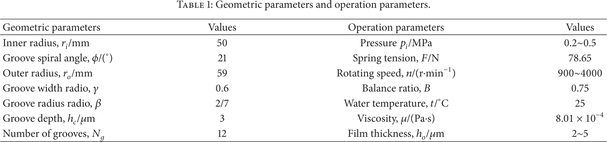
In this study, the face structure of mechanical seal with spiral grooves (Figure 2) and fundamental geometric parameters and operation parameters (Table 1) were shown. The spiral grooves were designed on the surface of rotating ring, while the molded lines were spiral lines described with a known formula: r = r i e θtanϕ . In order to observe the lubrication film (Figure 3), the film thickness was magnified 1000 times.
Geometric parameters and operation parameters.

The face structure of spiral grooves mechanical seal.
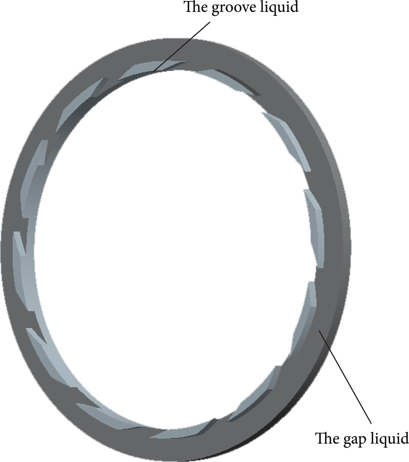
The model of fluid film.
2.2. Meshing and Boundary Conditions
1/N g of the film was selected to research because the spiral grooves were arranged periodically. The grid was meshed with the unstructured grid with the pretreatment software Gambit. To take the reliability of the grid number and quality on simulating deviation into consideration, the grid independence test of film was taken by four mesh sizes in different directions. Besides, the opening force was chosen as the criterion of convergence. The change of opening force obtained was sTable with scheme 4, which indicated the correlation between grid number and numerical results was very small. Meshing schemes and analysis results were shown in Table 2 and so scheme 4 was selected. Gird results of film flow field were shown in Figure 4 and the thickness shown was magnified 1000 times.
Meshing scheme.


1/N g fluid film mesh and boundary conditions.
The boundary conditions were also shown in Figure 4. In addition, the volume fraction of the vapor phase was 0, and the volume fraction of liquid phase was 1 in the inlet boundary condition options. The formulation was as follows:
periodic boundary condition: φ(θ + 2π/N g ) = φ(θ),
cavitation boundary condition: P < P v , P = P v , P v is the saturation vapor pressure, and ∂P/∂n = 0.
2.3. Applied Dynamic Mesh
In this study, the relationship of opening force Fopening, closing force Fclosing, and film thickness h was compiled by fluent user defined function (UDF); in addition, force balance of the mechanical seal was sought by adjusting the film thickness with dynamic mesh technique [10]. It is assumed that the opening force would be maintained to balance the closing force with absolute error which is controlled in 0.1 due to the impact of film stiffness and the computational accuracy, so the solution frame was shown in Figure 5.

Flow chart of dynamic mesh program.
3. Mathematical Model
3.1. Governing Equation
Multiphase flow cavitation model Zwart-Gerber-Belamri (ZGB) discussed by Zwart et al. [11] was derived from full cavitation model by Singhal et al. [12]. The distinctions between two models were the expression of growth and collapse of the vapor bubbles. The full cavitation model has taken into account the impact of noncondensable gas, while ZGB model consideration was nucleation on account of better convergence speed and stability, so the governing equation was as follows:
continuity equation

momentum equation

vapor transport equation

where ρ m is the mixture density; ρ m = ∑n = 12α n ρ n ; v m is the mass-averaged velocity; v m = ∑n = 12α n ρ n v n /ρ m ; ρ n ,v n , and α n were the density, velocity, and volume fraction of phase n. μ m is the viscosity of the mixture; μ m = ∑ n 2α n μ n . In (2), the slip velocity for vapor phase was ignored. In (3), v is the vapor phase; α is the vapor volume fraction; R e , R c are mass transfer source terms connected to the growth and collapse of the vapor bubbles, respectively, which were described as follows:

where
3.2. Simplified Condition
To calculate the cavitation area of mechanical seal conveniently it was necessary to simplify some factors that have little influence on the results, which were shown as follows:
the fluid flow of film was laminar [13] and continuity hypothesis was applied;
the body force was neglected, such as gravity and centrifugal force;
the fluid was isothermal; temperature was 25°C;
there was no slip velocity between seal surface and fluid medium;
the microdeformation of seal rings was ignored.
4. Results and Discussion
4.1. Experimental Verification of the Cavitation Model
Peng et al. [14] measured the thickness of the film with the eddy current displacement sensor. A comparison of film thickness from experimental data of Peng and the solution obtained when using the above cavitation models versus the one obtained when not using cavitation model was shown in Figure 6.

Comparison of noncavitation, cavitation, and experimental film thickness.
From the results presented in Figure 6, it was clear that the biggest relative error was 15.2% or the average relative error was 7.0% when the cavitation was not considered. The solution was closer to experimental data when using the ZGB model than Singhal et al. model, so it was more reasonable to apply the ZGB model. The reason of larger error was overlooking negative pressure in the cavitation area, which would result in a wrong opening force of the lubrication film. So the cavitation phenomenon was one of the reasons for the formation of the lubrication film.
4.2. Cavitation Region Analysis of Film
According to plentiful research of cavitation [15, 16], it was clear that the cavitation of lubrication film generated in mechanical seal was connected with the surface structure, fluid properties (viscosity, nuclei, and vapor pressure), sealed pressure, and rotating speed. The sealed pressure and speed were the primary factors affecting the region of cavitation on account of the designed seal structures and medium properties in this study. For convenience, the cavitation number meaning the extent of cavitation was described by the following function:
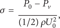
where P0 is the static pressure without disturbance, P v is the saturation vapor pressure, and U0 is the freestream velocity under P0.
4.2.1. Vapor Bubbles Volume Fraction Distribution
To analyze the location, extent, and cavitation regions that occurred in the lubrication film, Figure 7 showed vapor bubbles volume fraction distributions of the lubrication film from cavitation inception to steady state or different aspects along the thickness direction at different instants of time when cavitation number was 1.65, of which it reached steady state at 0.03 seconds, which was shown in Figure 7(d).
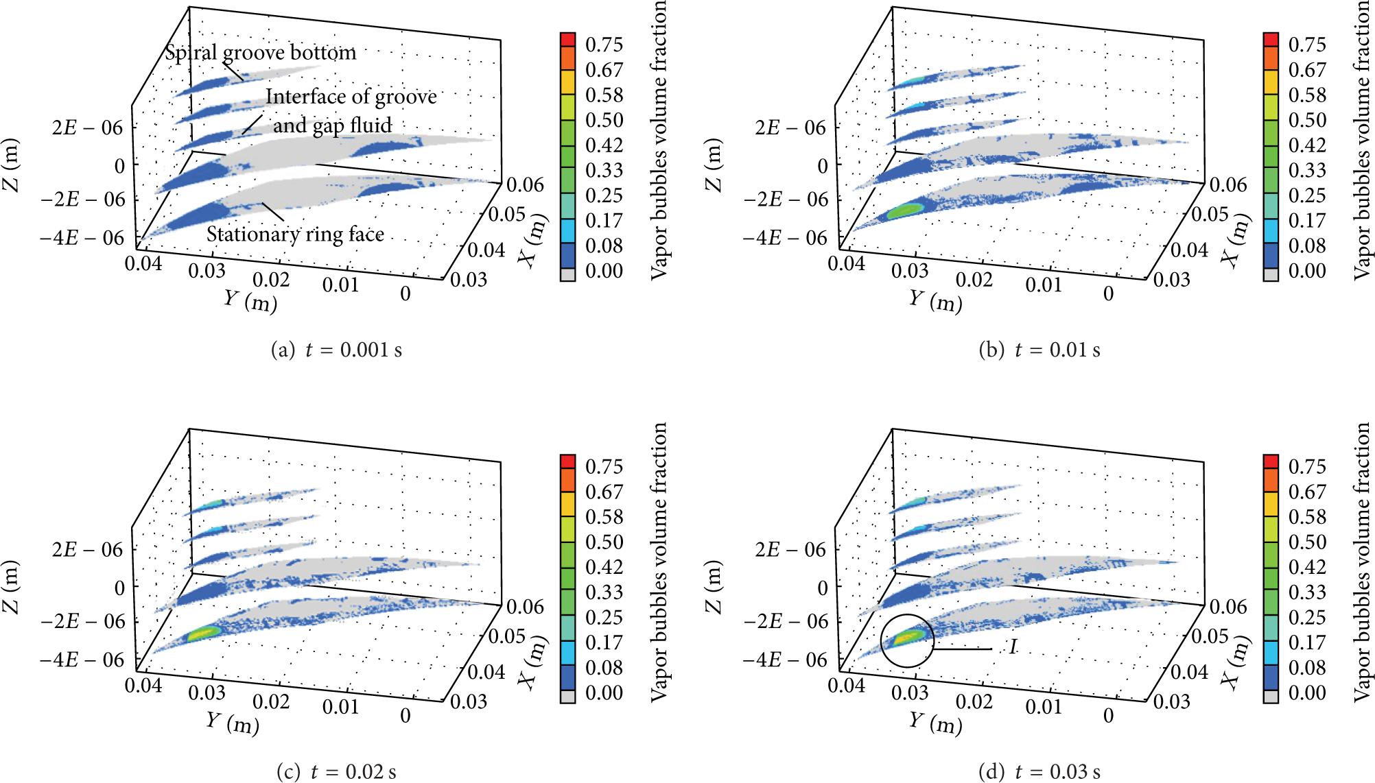
Vapor bubbles transient distribution in different directions when σ = 1.65.
Distributions of vapor bubbles shown in Figure 7 have predicted the regions of cavitation inception located in the concave side of spiral grooves and surrounding regions without spiral groove, which was shown in Figure 7(a). Besides the scope of cavitated area was nearly covered by the inner radius to roots of grooves; what is more, the location and scope of cavitation were consistent along the thickness direction including the spiral groove bottom, interface of groove, and gap fluid or stationary ring face. It illustrated that the cavitation was resulting from pumping effect and hydrodynamic effect. The volume fraction of vapor bubbles occurred in the concave side of spiral grooves and the near area of stationary ring face was increased with the gradual development of cavitation, in particular, cavitation regions of the stationary ring surface raised obviously, while the changes of cavitation regions were unconspicuous in other surfaces, which was shown in Figures 7(b) and 7(c). Hence, it made the local flow complex and produced eddies due to surface engineering and the velocity gradient of stationary ring face, which resulted in the increasing energy loss of fluid to aggravate the cavitation extent of the low pressure area and generate added vapor bubbles.
From Figure 7, as can be seen, cavitation regions were stable relative in the whole film. It indicated that the cavitation region maintained the steady fluid flow along the profile of different thickness. However, a little of vapor bubbles occurred on the surface with a slight cavitation area, especially the near area at the inner radius. It indicated that hydrostatic pressure of the near area at the inner radius was still low due to pumping effect; the cavitation gradually became smaller from a low pressure area to a high pressure area because of the collapse of bubbles, but it has failed to collapse completely. From the above distributions, it was clear that the surface of the stationary ring was the primary area of cavitation. So region I of Figure 7(d) was analyzed intensively in the following paper.
4.2.2. Effect of Rotating Speed
The rotating speed and sealed pressure have important influence on cavitation area in a thin film. Figure 8 presented distributions of vapor bubbles in the primary area of cavitation with diverse rotating speeds and sealed pressure. From the graphs in Figure 8, it was shown that the location of cavitation area was unchanged with variational rotating speeds, but the scope of which became larger obviously following increasing rotating speeds. It indicated that the velocity of fluid film has significant influence on the cavitation in the clearance gap. Meanwhile, the boundary of cavitation regions was smooth when mechanical seals operate at a low rotating speed; in addition vapor bubbles were concentrated relatively and the volume fraction of the core area became comparatively large. As the speed was increased to a high value, the boundary of cavitation regions appeared rough, which means the seal stability was declining on account of the complex fluid flow and the cavitation area was increased with high rotating speeds. The metabolic tendency of maximal volume fraction was lifting when the boundary of cavitated area appeared roughly following increasing rotating speeds. From the above analysis, we can see that the cavitation extent was aggravated, which was beneficial to improve the opening force and film thickness; it improved the performance of lubrication in the clearance gap; however, it made the sealing stability decline.
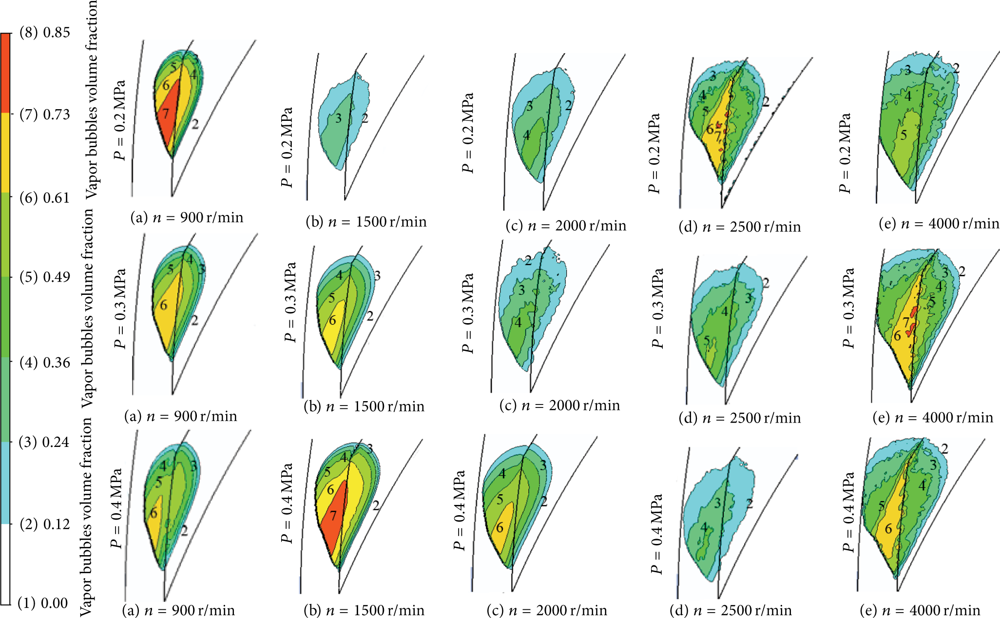
Vapor bubbles volume fraction distribution of region I at different operating conditions.
4.2.3. Effect of Sealed Pressure
From the results presented in Figure 8, it was shown that the closing force was related to sealed pressure because of the decided seal structures. Seal rings were operated steady by adjusting the film thickness level at different working conditions. With increasing sealed pressure, it raised the average film pressure, which caused the cavitation number to become larger and the film thickness was decreased at the constant rotating speed. Moreover, the rotating speed converting the boundary of cavitated area from smooth to rough was raised with the unchanged scope of relative cavitation regions. However, the highest volume fraction was descending with increasing sealed pressure at the constant rotating speed when the boundary of cavitation was smooth or rough simultaneously.
The boundary of cavitation converting from smooth to rough was relevant to the cavitation number and film thickness through computed results. It was also found that the transformation occurred at similar film thickness and cavitation number.
5. Conclusions
(1) To obtain more realistic results, the cavitation must be considered in allusion to the simulation of inner fluid flow in Upstream Pumping Mechanical Seal. A comparison of film thickness from experimental data and the solution obtained when utilizing the above cavitation models has shown that it was more precise by using the ZGB model.
(2) Regions of cavitation inception were located in the concave side of spiral grooves and surrounding regions without spiral groove, which was nearly covered by the inner radius to roots of grooves. It illustrated that the cavitation was resulting from pumping effect and hydrodynamic effect. With the development of cavitation, the rising tendency of volume fraction in stationary ring face was most distinct, which indicated the surface of the stationary ring was the primary area of cavitation.
(3) Scope of cavitated area was invariant basically following increasing medium pressure at the constant rotating speed, which increased with the increment of rotating speed at the constant medium pressure. The boundary of cavitated area converted from smooth to rough occurred in similar film thickness at different operating conditions. With the decrease of the cavitation number, cavitation extent was anabatic, which helped in improving opening force and film thickness, promoting the lubrication performance of film in mechanical seal.
However, the service life was influenced by the declining stability of lubrication film and even caused cavitation erosion. Therefore, how to design the optimizing surface structure of mechanical seals to control the cavitation area reasonably and take advantage of them to avoid seal failure or cavitation erosion, which have an important theoretical significance and engineering practical value that needed to be further research.
Conflict of Interests
The authors declare that there is no conflict of interests regarding the publication of this paper.
Footnotes
Acknowledgments
The authors gratefully acknowledge the support of the National Natural Science Foundation of China (no. 51279067) and Aviation Science Funds (no. 201328R3001).