
Abstract
Intelligent controllers are studied for vibration reduction of a vehicle consisting in a semiactive suspension system with a magnetorheological(MR) damper. The vehicle is modeled with seven degrees of freedom as a full vehicle model. The semiactive suspension system consists of a linear spring and an MR damper. MR damper is modeled using Bouc-Wen hysteresis phenomenon and applied to a full vehicle model. Fuzzy Logic based controllers are designed to determine the MR damper voltage. Fuzzy Logic and Self-Tuning Fuzzy Logic controllers are applied to the semiactive suspension system. Results of the system are investigated by simulation studies in MATLAB-Simulink environment. The performance of the semiactive suspension system is analyzed with and without control. Simulation results showed that both Fuzzy Logic and Self-Tuning Fuzzy Logic controllers perform better compared to uncontrolled case. Furthermore, Self-Tuning Fuzzy Logic controller displayed a greater improvement in vibration reduction performance compared to Fuzzy Logic controller.
1. Introduction
In recent years, control systems with semiactive elements, such as magnetorheological (MR) dampers, have attracted great attention in control engineering from both theoretical and practical point of view. Increased attraction to semiactive elements is developed due to their comparable reliability against passive systems and lower energy consumption compared to active systems. MR dampers are semiactive devices that are controlled by magnetic field. MR dampers are semiactive control elements that can be described as a hydraulic cylinder filled with MR fluid. MR fluids typically consist of micron-sized, magnetically polarizable ferrous particles dispersed in a carrier medium such as mineral oil. When a magnetic field is applied to MR damper, particle chains form and the MR fluid changes from viscos liquid to semisolid. Therefore, the damping force that is produced by MR damper can be changed by applied magnetic field. This provides good performance over passive dampers. Moreover, MR dampers reduce vibrations by absorbing energy from the system and they do not destabilize the system. Since the MR dampers allow online adjustment, control techniques can be applied easily [1–4].
MR dampers possess nonlinear hysteresis behavior, which has made modeling MR dampers a challenging problem for investigators. Several modeling approaches have been used to mimic the characteristics of the nonlinear hysteresis. For example, quasistatic models, models based on Bingham, Bouc-Wen friction, Fuzzy Logic, and genetic algorithms, are used to model the dynamic MR damper behavior. Although models based on Bouc-Wen friction principle bear some difficulties in determining the behavior and parameters of the system because of its complex structure, some of these models can model the dynamic behavior of the MR damper successfully [1, 2]. Therefore, a Bouc-Wen based MR damper model is used in this study.
MR damper creates a reaction force when a displacement is applied to its tips. Magnitude of the damping force can also be tuned by the applied magnetic field. Thus, obtaining desired damping, in response to a constant displacement, directly depends on voltage of the MR damper. One of the main issues in semiactive control with an MR damper is the development of an appropriate control algorithm to determine voltage of the MR damper. Spencer et al. modeled the MR damper and applied it successfully to a structural system [1, 2]. Cetin et al. used the MR damper to reduce structural vibrations of a structural system with six degrees of freedom (DOFs). An adaptive nonlinear controller and an H∞ robust controller are applied experimentally [3, 4]. Song et al. designed an adaptive semiactive control algorithm for magnetorheological suspension systems [5]. Ying et al. developed a stochastic optimal semiactive control strategy for ER/MR dampers. A dynamic programming equation to constrain ER/MR damping forces is used to determine the optimal control law effectiveness of the proposed controller. The effectiveness of the controller is illustrated in two examples [6]. El-Kafafy et al. studied a quarter vehicle model with two DOFs incorporating an MR damper. The MR damper is modeled with Bouc-Wen friction principle. In this study, a sliding mode controller is used to control the MR damper. Simulation results showed the effectiveness of the controller in terms of vehicle road holding [7]. Liao and Lai used one DOF suspension system model with an MR damper. The Bouc-Wen model is used to model the MR damper. In this study, sliding-mode controller is applied to the semiactive control [8]. Du et al. used quarter vehicle model with an MR damper, which is controlled by an H∞ controller. The performance of the controller is investigated experimentally and theoretically. The results of each study were compared, in order to analyze the control performance of the quarter vehicle model with an MR damper [9]. Li et al. used a Fuzzy Logic controller and a microgenetics algorithm. The modified Bouc-Wen model was used to model the MR damper. The controller performance is verified by simulation studies [10]. Metered et al. applied neural networks (NN) algorithm to an MR damper for a quarter vehicle model. The performance of this algorithm in terms of vibration damping by the MR damper is investigated via hardware in the loop simulation (HILS) test setup [11]. Zapateiro et al. used the H∞ based backstepping and the quantitative feedback theory (QFT) algorithms for MR dampers. The performance of the semiactive control is evaluated using simulation studies in MATLAB-Simulink software. Besides, Fuzzy Logic based controllers are widely used to reduce vehicle vibration along with the active suspension systems [12]. Guclu designed a Fuzzy Logic controller for a half vehicle model to reduce vibration without suspension gap degeneration. Simulation studies showed the effectiveness of the controller in terms of ride comfort [13]. Guclu investigated the dynamic behavior of an eight-DOF vehicle model with passenger seats and suspensions. The model was nonlinear due to dry friction. This is used to reduce seat vibrations. The success of Fuzzy Logic controller system is verified by simulations [14].
In this paper, semiactive suspension system with an MR damper is used to reduce vehicle vibrations. Fuzzy Logic based controllers are developed. The semiactive suspension system consists of an MR damper and a linear spring. The MR damper is modeled using Bouc-Wen behavior. The MR damper voltage is determined by Fuzzy and Self-Tuning Fuzzy Logic controllers. Energy absorption of MR damper is changed according to displacement and velocity. Therefore, the controllers proposed in this study are designed taking into account both the displacement and the velocity of MR damper.
The performance of the controllers is evaluated via MATLAB-Simulink simulation studies. The performance of the semiactive suspension system is analyzed with or without control. Simulation results showed that both Fuzzy and Self-Tuning Fuzzy Logic controllers perform better compared to the uncontrolled case. Furthermore, Self-Tuning Fuzzy Logic controller displayed a greater improvement in vibration reduction performance compared to Fuzzy Logic controller. The rest of the paper is organized as follows: the MR damper model and mathematical model of the system are given in Section 2, the Fuzzy Logic based control algorithms are presented in Section 3, the simulation results are discussed in Section 4, and conclusions are presented in Section 5.
2. Mathematical Modeling of System
2.1. MR Damper Model
MR damper is a hydraulic cylinder which consists of a piston, a magnetic coil, and MR fluid. MR fluid is a liquid that can be easily controlled. Physical model of an MR damper is shown in Figure 1 [3].
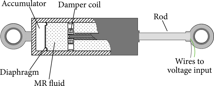
MR damper model [3].
MR fluid consists of micron-sized, magnetically polarizable particles dispersed in a carrier fluid such as mineral or silicone oil. The fluid properties can vary with the intensity of the applied magnetic field. When a magnetic field is applied to the MR fluid, magnetically polarizable particles take a chain form and MR fluid exhibits a semisolid behavior. This behavior can be achieved in a few milliseconds. Additionally, MR fluid can operate at temperatures ranging between −40°C and 150°C. Due to MR dampers’ nonlinear hysteresis behavior, Bouc-Wen model, which is widely used for modeling hysteresis systems, is used to model the MR damper in this study [1, 2]. Bouc-Wen based MR damper model, which is called “proposed Bouc-Wen model” from now on, consists of an additional damping element connected in series and a spring element connected in parallel to the simple Bouc-Wen model. Moreover, the dynamics of the MR damper winding is added to the model as a first-order filter. The proposed Bouc-Wen model of the MR damper is shown schematically in Figure 2 [2].

The proposed Bouc-Wen model of the MR damper.
The equations of the proposed Bouc-Wen model can be derived as follows [2]. Considering only the upper section in Figure 2, forces on either side of the rigid bar can be given as

where evolutionary variable z is defined as

and when (1) is solved, the following equivalent is obtained:

The total force generated by the system is determined by summation of the forces on either side of the system in Figure 2, yielding

In this model, k1 is the accumulator stiffness and c0 is the viscous damping observed at larger velocities. c1 is a dashpot, which produces the roll-off observed at low velocities. z is Bouc-Wen variable; α1 and A are functions of the applied magnetic field and hysteresis loop. γ, n, and β are constants related to hysteresis loop which is related to the MR fluid [2]. k0 is the stiffness at large velocities. x0 is the initial displacement of spring (k1) associated with the nominal damper force due to the accumulator [2]. The effect of magnetic field arises from voltage applied to windings of the MR damper and can be described as

where u is a first order filter that is defined as

In (6), V represents the applied voltage to MR damper windings.
2.2. Mathematical Model of Full Vehicle
A seven-DOF semiactive full vehicle model is used in this study. A schematic drawing of the full vehicle model is shown in Figure 3 [14].

Full vehicle model.
This full vehicle model has seven degrees of freedom, which are given as x1,x2,x3,x4,x5,x6 = θ, x7 = α, respectively. The model consists of a body and four wheels, which are connected with four suspension systems. Each suspension system consists of a linear spring and an MR damper. The wheel spring is in contact with the road profile. All system components, except the MR damper, have been considered as linear. The dynamic differential equations of this semiactive full vehicle model can be given as
where M represents the vehicle body mass and m1–4 stand for the wheel masses. The linear spring stiffness of the suspension systems is demonstrated by ks1 − 4 and the linear spring stiffness of vehicle tires is illustrated by kt1–4. x1–4 stand for the vertical motions of the wheels. z1–4 are defined as the road function. Passive dampers are demounted and MR dampers are attached to the system. Damping forces of the MR dampers are evaluated using the mathematical model based on the Bouc-Wen hysteresis model. The MR damper which is attached to the front left side of the vehicle is represented by F MR fl ; the MR damper which is mounted to the front right side of the vehicle is symbolized by F MR fr . The MR dampers which are connected to the rear left and rear right sides of the vehicle are denoted by F MR rl and F MR rr , respectively. Vref is the speed of the vehicle.
3. Control Algorithms
Well-known proportional-integral-derivative (PID) controller is most widely used in industrial applications due to its simple structure. However, conventional PID controllers with fixed gains do not yield reasonable performance over a wide range of operating conditions and systems (time-delayed systems, nonlinear systems, etc.). Control techniques based on Fuzzy Logic and Modified Fuzzy Logic controllers are alternatives to conventional control methods. Fuzzy Logic based controllers are frequently used in vehicle vibration reduction problems [13–17].
3.1. Fuzzy Logic Controller
Fuzzy Logic controller (FLC) used in this paper is based on two-input and one-output FLC structure. The overall structure of the controller used in this study is shown in Figure 4.
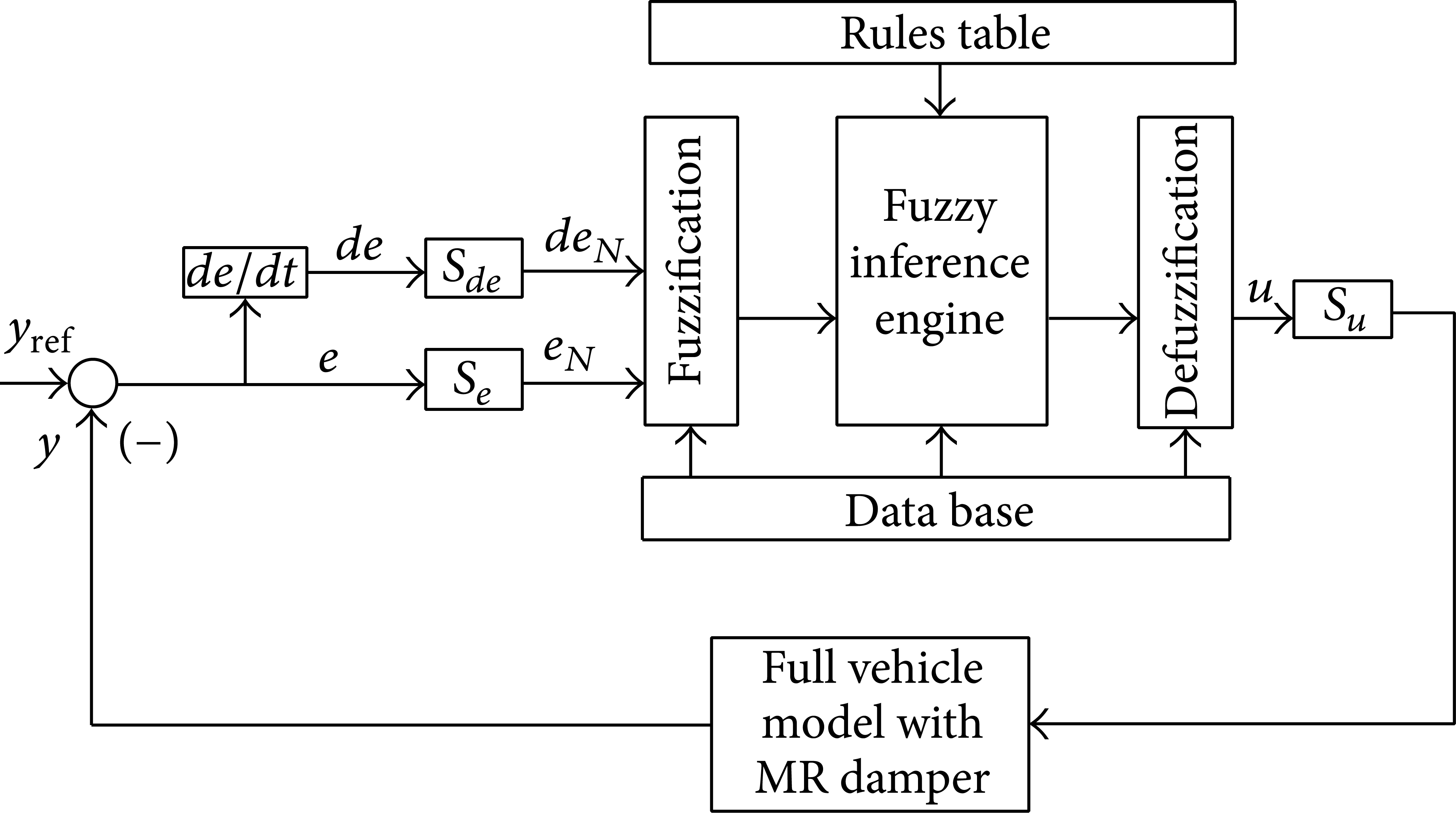
Block diagram of the two-input one-output Fuzzy Logic controller.
FLC has two inputs and one output. The inputs of the FLC are error (e) and error change (de), and the output of FLC is control signal of the MR damper. Linguistic variables which imply inputs and output have been classified as NB, NM, NS, ZR, PS, PM, and PB. Inputs are all normalized in the interval of [− 1, 1] and the output is normalized [0, 1] as shown in Figure 5. The variables are scaled with coefficients of S e , S de , and S u . The Fuzzy Logic control rules are in the form of

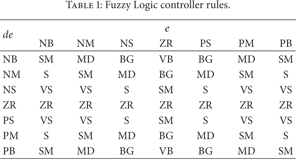
The rules are derived from basic knowledge and experience related to the system. These rules are written in a rule base lookup table which is shown in Table 1. The rule base structure is Mamdani type. The linguistic labels used to describe the Fuzzy sets for inputs are “Negative Big” (NB), “Negative Medium” (NM), “Negative Small” (NS), “Zero” (ZR), “Positive Small” (PS), “Positive Medium” (PM), and “Positive Big” (PB). The linguistic variables used to denote the Fuzzy sets for output are “Zero” (ZR), “Very Small” (VS), “Small” (S), “Small Medium” (SM), “Medium” (MD), “Big” (BG), and “Very Big” (VB). Set of decision rules, as shown in Table 1, can be assigned. These rules contain input/output relationships that define the control strategy. Each control input has seven Fuzzy sets so that there are at most 49 fuzzy rules. In this study the displacement at the upper end of the MR damper is expressed as (e) and the velocity at the upper end of the MR damper is evaluated as (de).
Fuzzy Logic controller rules.

Membership functions of inputs ((a), (b)) and output (c).
3.2. Self-Tuning Fuzzy Logic Controller
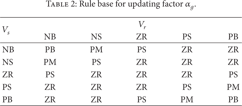
The main aim of the Self-Tuning Fuzzy Logic controller (STFLC) is to achieve an optimal controlled system by changing the controller gain. Figure 6 schematically shows the general structure of the STFLC. STFLC controller gain is obtained by multiplying the Fuzzy Logic controller output gain of S u with an update factor of α g . The gain updating factor α g is determined by using V r and V s and according to Fuzzy rule table that is given in Table 2. Therefore, output gain of the STFLC changes by the updating factor [18–20].
Rule base for updating factor α g .

Block diagram of the Self Tuning Fuzzy Logic controller.
Linguistic variables for inputs which are used to design STFLC have been classified as “Negative Big” (NB), “Negative Small” (NS), “Zero” (ZR), “Positive Small” (PS), “Positive Medium” (PM), and “Positive Big” (PB). “Zero” (ZR), “Positive Small” (PS), “Positive Medium” (PM), and “Positive Big” (PB) are used as linguistic variables for the output in Figure 7. The gain updating factor, which is a variable coefficient, is determined by these linguistic variables. V r and V s , which are used to determine the updating factor α g , are defined as relative velocity at either end of the MR damper and the velocity at the upper end point of the MR damper, respectively.

Membership functions of inputs ((a), (b)) and output (c).
4. Simulation Results
In order to verify the effectiveness of the utilized controller, the following numerical simulations are performed in MATLAB-Simulink environment. The mathematical model of the vehicle suspension system as defined in (7) and the system parameters are listed in Table 4 and are used in the simulation studies. Also, the MR damper parameters that are used in simulation are given in Table 5 [8]. Hysteresis behavior of the MR damper is shown in Figure 8, where a displacement of 0.007 m amplitude and 2 Hz frequency is applied to the MR damper. MR damper voltage is used as 0 and 1.5 V, respectively.

MR damper dynamic behavior.
In the simulation, the performances of the classical Fuzzy Logic controller and Self-Tuning Fuzzy Logic controller are compared to the passive suspension system with an MR damper. In the passive suspension system, the MR damper is kept connected to the system but the MR damper voltage is applied as 0 V. Therefore, the MR damper acts as a passive damper. In the other two cases, MR damper voltages are determined by FLC and STFLC, respectively. Totally, four Fuzzy Logic controllers are used in this study (one controller for one suspension). The controllers are independent; however, the Fuzzy Logic controllers have the same properties (such as the same rules, the same membership functions, and the same scaling factor). Simulation studies are carried out with an upward bump function for the road which is illustrated in Figure 9 [21]. In the simulation study, firstly the front two wheels of the vehicle are going through the bump simultaneously and then the rear two wheels pass the bump simultaneously.

The road function used in simulations.
Comparisons between semiactive controlled cases and passive case are evaluated in terms of body vertical displacement, angular displacements, body vertical acceleration, and angular acceleration. In addition to this, each suspension deflection of the vehicle is investigated. The results of the simulations are reported in Figures 10–16. The results of vehicle body motions are depicted in Figures 10–12. In Figure 10, comparison of the vertical displacement of the vehicle body is presented. Figures 11 and 12 show the pitching and the rolling motions of the full vehicle body, respectively. In these figures, FLC and STFLC are achieved to reduce vertical and angular body motions. Fuzzy Logic controller considerably decreases the displacement of pitching and rolling of the full vehicle body motion. Furthermore, the Self-Tuning Fuzzy Logic controller provides more reduction than the Fuzzy Logic controller.

The vertical body displacement of full vehicle model.

Pitch angular displacement of full vehicle model.

Roll angular displacement of full vehicle model.

Vehicle body vertical acceleration of full vehicle model.

Vehicle body pitch angular acceleration of full vehicle model.

Vehicle body roll angular acceleration of full vehicle model.
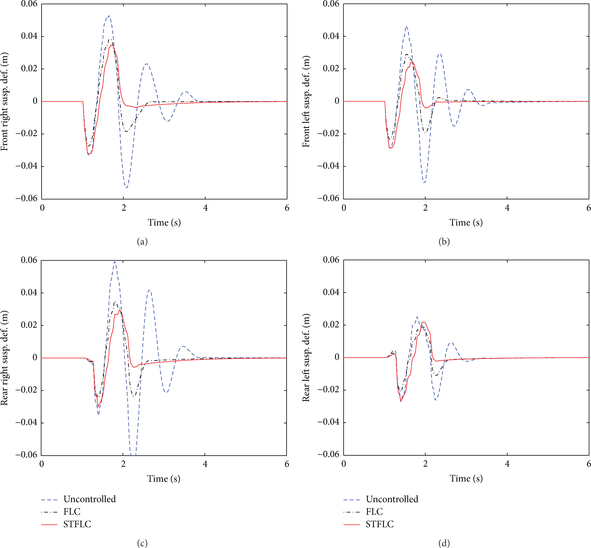
Suspensions deflection of full vehicle model.
In Figures 13, 14, and 15, acceleration responses of the vehicle body are illustrated. Both of the controller's performances are well in terms of vertical and angular acceleration of the vehicle body. Moreover, STFLC performance is better than FLC. Results presented in these figures showed that the amplitudes of the vertical and angular motion are decreased by Fuzzy Logic controllers. Figure 16 shows that both of the controllers diminished suspension deflections considerably better than the uncontrolled passive system. Furthermore, STFLC achieved a greater reduction compared to FLC. Also, designed controllers’ performances are evaluated in terms of the following performance indices that are commonly used in control techniques [22]:


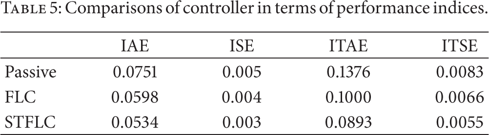
Four criteria that are considered are the integral absolute error (IAE), the integral of time multiplied absolute error (ITAE), the integral of squared error (ISE), and the integral of time multiplied squared error (ITSE). All of these criteria reflect a different aspect of the controller performance. Comparisons of utilized controllers in terms of four performance indices can be seen in Table 3. As mentioned above, performances of both FLC and STFLC are better than the passive uncontrolled system. In comparison with the passive system, FLC and STFLC reduce IAE by 21% and 29%, respectively. The controllers have also 28% and 66% reduction in ITAE performance index. FLC and STFLC have 20% and 40% reductions in ISE, respectively. Also both of the controllers reduce the ITSE values. Overall, STFLC control scheme provides a better performance than FLC (Table 3).
Vehicle model parameters.

MR damper model parameters used in simulation.

Comparisons of controller in terms of performance indices.
5. Conclusions
In this study, the vehicle vibrations caused by road roughness are reduced by using a semiactive suspension system. The full vehicle model has seven DOFs and the passive dampers of the vehicle model are replaced with MR dampers. The magnetorheological (MR) damper is attached to the vehicle model as a semiactive element. The Bouc-Wen friction principle based mathematical model is used to determine the nonlinear dynamic behavior of the MR damper. The damping force of the MR damper is changed by adjusting voltage. For this purpose, the controllers based on Fuzzy Logic are used to evaluate the MR damper voltage. Energy absorption of MR damper is changed according to displacement and velocity. Therefore, the controllers proposed in this study are designed taking into account both the displacement and velocity of MR damper.
The classical Fuzzy Logic controller (FLC) and Self-Tuning Fuzzy Logic controller (STFLC) have been implemented as controllers. The performance of the controllers has also been discussed. The aim of these controllers is reducing the vehicle body motion by adjusting the MR dampers voltage and ensuring the comfort of passengers. Due to the damping force of MR damper, vehicle vibrations are reduced. MATLAB-Simulink simulation results showed that the Fuzzy Logic controllers are able to decrease vibrations in the semiactive full vehicle model, so that ride comfort can be maintained. According to the simulation results, the STFLC controller is more effective compared to the FLC controller.