
Abstract
For numerically simulating 3D solid-liquid turbulent flow in low specific speed centrifugal pumps, the iteration convergence problem caused by complex internal structure and high rotational speed of pump is always a problem for numeral simulation researchers. To solve this problem, the combination of three measures of dynamic underrelaxation factor adjustment, step method, and rotational velocity control means according to residual curves trends of operating parameters was used to improve the numerical convergence. Numeral simulation of 3D turbulent flow in a low specific speed solid-liquid centrifugal pump was performed, and the results showed that the improved solution strategy is greatly helpful to the numerical convergence. Moreover, the 3D turbulent flow fields in pumps have been simulated for the bottom ash-particles with the volume fraction of 10%, 20%, and 30% at the same particle diameter of 0.1 mm. The two-phase calculation results are compared with those of single-phase clean water flow. The calculated results gave the main region of the abrasion of the impeller and volute casing and improve the hydraulic design of the impeller in order to decrease the abrasion and increase the service life of the pump.
1. Introduction
With the development of computational fluid dynamics, research means and methods on fluid mechanics and solid-liquid two-phase fluid dynamics have been greatly improved. These advances have led the researchers to delve into in-depth research for solid-liquid two-phase turbulent flow in slurry pump which was difficult to solve in the past 10 years [1, 2]. Nowadays, the numerical simulation of turbulent fluid flow has become a hot topic, such as direct numerical simulation (DNS) [3–7], large eddy simulation (LES) [8–13], and Reynolds algebraic stress model (RAMS) [14–16]. However, multidimensional nonlinear partial differential equations in the model are very complicated. The existing mathematical theory is not enough, and the strict stability analysis, error estimation, and convergence theory development also cannot keep up with the progress of numerical simulation [17]. Therefore, the necessary discussion on the solution convergence method is of great significance in understanding the real internal flow in solid-liquid pump.
In addition, to understand the influence of internal flow on the performance of a solid-liquid centrifugal pump, it is necessary to further study the solid-liquid two-phase flow mechanism mainly including particle collision mechanism, particle trajectory, concentration distribution, velocity distribution, and pressure distribution of both phases in a centrifugal slurry pump, and the research is of great significance to reduce abrasion, prolong the service life, and promote design for the solid-liquid two-phase flow pump. More and more researchers have used CFD technology to study the solid-liquid two-phase flow inside the pump [18–20]. Wang et al. [21] studied the flow structure of the particle-liquid two-phase flows through the impeller of a centrifugal slurry pump. The solid-liquid two-phase turbulent flow fields in pumps have been simulated for the sand-particles with the granule diameter of 0.5 mm, l mm, and 2 mm. Li et al. [22] studied the flow field in the slurry pump using CFD software. The distribution of velocity and the information of axial vortex in the impeller and volute were discovered. Using FLUENT software with mixture model, extended SIMPLEC algorithm, and standard k-ε turbulence model, Zhao et al. [23] studied 3D turbulent flow in double-channel pump and concluded that the volume fraction contour is extremely nonuniform in channels of impeller, and solid particles mainly accumulate on pressure sides of impeller but tend towards suction side on the conditions of low sandy volume fraction and small particle diameter. Ding and Su [24] simulated solid-liquid two-phase turbulent flow in double blades screw centrifugal pump, and the results showed that the head of pump declines with the increase of solid phase volume fraction and decreases with the increase of particle diameter. Bross and Addie [25] developed a simple model to predict the influence of different impeller design parameters on the wear behaviour of the impeller suction sealing.
Research on the flow in a centrifugal pump has been undertaken by many researchers in the last two decades, but there are still many doubts to resolve, especially for the low specific speed solid-liquid centrifugal slurry pump with complex internal structure. The existing conclusions obtained in various experimental conditions of slurry pump are not the same, which limits their application scope. In the present study, based on previous studies, according to flow characteristics inside centrifugal pump and the two-fluid model theory of solid-liquid two-phase flow, a set of adequate equations including the basic equation and flow control equation for solid-liquid two-phase flow in centrifugal slurry pump were introduced. The combination of three measures of dynamic underrelaxation factor adjustment, step method, and rotational velocity control means according to residual curves trends of operating parameters was used to improve the numerical convergence. Numeral simulation of 3D turbulent flow in a low specific speed solid-liquid centrifugal pump was performed based on Euler-Euler two-fluid model, and the results showed that the improved solution strategy is greatly helpful to the numerical convergence. Moreover, the solid-liquid two-phase turbulent flow fields in pumps have been simulated for the bottom ash-particles with the volume fraction of 10%, 20%, and 30%, and the calculation results of two-phase flow were compared with those of single-phase clean water flow.
2. Control Equations for Solid-Liquid Two-Phase Flow in Centrifugal Pump
2.1. Continuity Equation
Consider
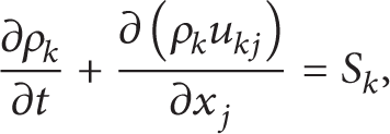
where the subscripts of k = f, s are denoted as liquid and solid phases, respectively, ρ k is apparent density, u is velocity vector, S is source term, S f = − S s = n s (dm s /d t ), and ρ s = n s m s = n s πd s 3ρ ss /6. Here, n s is particle numbers of per unit volume; m s is the mass of a single particle; ρ ss is particle material density; d s is particle diameter; and t is time.
2.2. Momentum Equation
The effect of the impeller rotation on the internal flow in centrifugal pump is introduced by adding the centrifugal force and the Coriolis force to the momentum equations. Furthermore, the momentum equation needs to convert from absolute to relative coordinates. The centrifugal force can be incorporated into the pressure phase; thus we have

where P k is reduced pressure of k phase, p m is total pressure of mixture, and C vk is volume fraction of k phase, C vp + C vf = 1.
Then, relative velocity momentum equation in the rotating reference orthogonal coordinate system can be obtained as
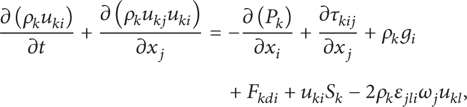
where ε jli is a cyclic permutation tensor (j, l, i = 1, 2, 3) and ω j is the component of angular velocity in impeller.
Consider F
sdi
= − F
fdi
= (ρ
s
/τ
rs
)(u
fi
− u
si
); τ
ij
= μ
t
((∂u
j
/∂x
i
) + (∂u
i
/∂x
j
)) − (2/3)λδ
ij
;
2.3. k f -ε f -k s Two-Equation Turbulence Model for Solid-Liquid Two-Phase Flows
2.3.1. k f -ε f Turbulence Equation for Liquid Phase
Turbulent flow in a centrifugal pump is anisotropic in that streamlines in the volute casing and the impeller are curved; namely, the turbulent viscosity μ k is anisotropic, so it will have a large effect on the turbulence results to use k-ε turbulence model to calculate the flow field in the centrifugal pump. Therefore, it is more appropriate to use RNG (renormalization group) k-ε turbulence model for computing turbulent flow of liquid phase in slurry pump since it can consider the anisotropy of μ k caused by curved surface. The turbulence kinetic energy equation k of liquid phase in RNG k-ε turbulence model is expressed as follows:
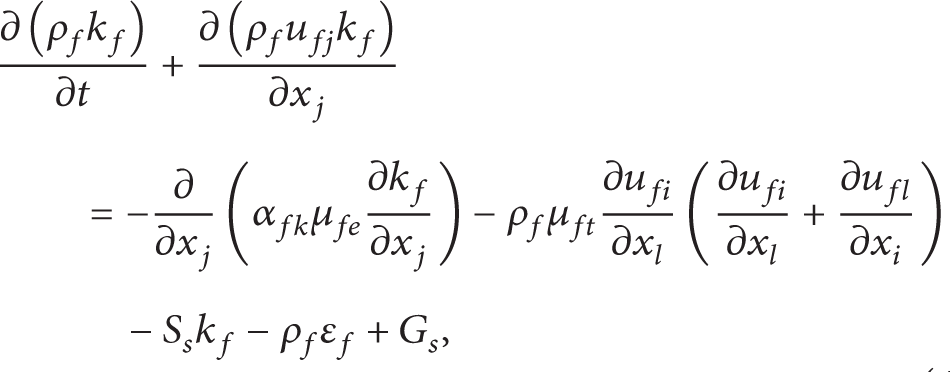
where
The turbulence kinetic energy dissipation equation ε of liquid phase is expressed as follows:

where α fk = α fε = 1.39, Cfε1 = 1.42, and Cfε2 = 1.68.
2.3.2. Turbulence Kinetic Energy Equation k s of Solid Phase
The classical model of Hinze-Tchen formula is referred to as A p model (algebraic particle turbulence model). It has its intrinsic defects of ignoring the generation, dissipation, and diffusion of particle turbulent kinetic energy and believes that the fluctuation characteristics of particles depend only on the local microfluid mass and particle pulsation is always less than fluid pulsation, which is inconsistent with the actual situation. So we must develop the transport equation for turbulent kinetic energy of particle phase. The turbulence kinetic energy equation k s of solid phase can be obtained by the description method of single-phase turbulent flow. Consider

2.3.3. k f -ε f -k s Model
In the same way as single-phase turbulent flow, we can suppose that v st = k s 1/2l s ,l s ~l f ~k f 2/3/ε f ; here l s is turbulent eddy scale of solid phase and l f is turbulent eddy scale of liquid phase. Then, v st = c vs k s 1/2l s k f 2/3/ε f ; the turbulence model k f -ε f of liquid phase and the turbulence kinetic energy model k s of solid phase form turbulence model k f -ε f -k s for solid-liquid two-phase flows.
3. Numerical Simulation of 3D Turbulence Flow Field of Solid-Liquid Centrifugal Pump
3.1. Solution Strategies and Methods for the Flow Field of Solid-Liquid Pump
Appropriate solution strategies and methods need to be adopted to make the computation of 3D turbulent flow field of solid-liquid pump obtain a faster convergence smoothly. Based on various solid-liquid pump numerical simulations, a suitable control method for 3D turbulent flow field in solid-liquid pump is proposed.
3.1.1. Underrelaxation Technique
In order to accelerate convergence, underrelaxation is usually applied. Practice shows that underrelaxation technique is an effective method to guarantee a reliable convergence theoretically for the pressure correction equation. The corresponding underrelaxation process should be made for pressure and velocity correction during implementation of the algorithm. The updated pressure is calculated by the following formula:
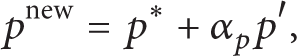
where pnew is the upgraded pressure, p* is the predicted pressure, p′ is the pressure correction value, and α p is the underrelaxation factor of pressure ranging from 0 to 1.
In general, larger α p can accelerate the convergence speed and smaller α p can improve stability and convergence of numerical computation. If one defines α p = 1, the predicted pressure field is directly corrected by p′. If the predicted value p* is higher or lower than the real solution with a huge difference, it will cause pnew overflow and numerical instability and even divergence. If a p is too small, the stable solution can be easily ensured with a poor convergence speed.
Underrelaxation process for velocity can be defined as follows:

where u i new is the updated components of velocity, u i is the modified components of velocity without underrelaxation, u i (n − 1) is the velocity component obtained by last iteration, and α i is the underrelaxation factor of velocity.
An appropriate underrelaxation factor plays a crucial role in increasing computational efficiency. The larger relaxation factor may cause solution oscillation or divergence, and the smaller factor may result in a lower convergence rate and huge computational time. Currently, there is no way to obtain the optimal underrelaxation factors because a reasonable underrelaxation factor depends on the flow solution itself, and the relaxation factor is determined by trial and error. For the solution of solid-liquid pump flow, the initial underrelaxation factors of each calculation parameter are listed in Table 1.
The initial underrelaxation factors of each calculation parameter.
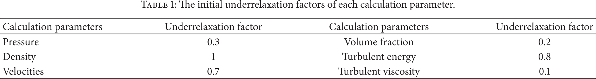
The basis of adjusting the underrelaxation factor is if the residual of a parameter begins to diverge or oscillate during the calculation process, the corresponding underrelaxation factor will be decreased to ensure the stability and convergence of iterative calculation; for the parameter with stable convergence, the underrelaxation factor can be properly increased to accelerate the convergence rate and shorten the time of calculation.
3.1.2. A Step Method to Calculate the Solid-Liquid Turbulent Flow Field in a Centrifugal Pump
The difficulty of applying CFD to solve solid-liquid pump flow field lies in the fact that the high speed rotational flow field caused by high speed rotating impeller brings about high coupling of momentum equation with an excessive rotation term. Meanwhile, the high rotary speed causes a large radial pressure gradient in radial flow direction. This coupling may cause unstable solution, so it is necessary to adopt a specific solution strategy and technology to obtain a converged solution. Therefore, a step method is proposed to solve the problem. The so-called step method is that only the selected equation in the solution process is activated at each step, and the other equation of the calculation model is temporarily closed.
3.1.3. Rotational Velocity Control Method
The rotation boundary conditions in solid-liquid pump make the flow more complex and have a poor computational stability when the rotational speed is increased to a high value. That is to say, it will have a great effect on the convergence of the solution. The most efficient method to solve the problem is a rotational velocity control method. The basic idea of the method is that a lower rotating speed is used in the beginning to solve the problem, and then the speed of rotation is gradually increased up to the required value.
3.1.4. Application of the Solution Strategies
Figures 1(a) and 1(b) show the variation of variable residuals with iteration numbers for the same computational model with and without the improved solution strategies, respectively. As can be seen from the figure, the variables of two phases began to oscillate or diverge quickly without using the improved solution strategy (Figure 1(a)). However, the residual curves oscillate slightly by changing the solution strategies, and then a quicker stable convergence is reached by calculating the mass flow rate of inlet and outlet with the improved solution methods (Figure 1(b)).
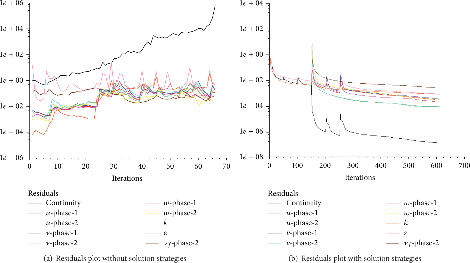
Residuals plots of computation.
3.2. 3D Modeling and Solution Method
Kumar gave detailed data on head, power, and efficiency in pumping clear water and solid-liquid two-phase mixtures (water and bottom ash) [26]. In order to compare with the experimental results, the centrifugal pump provided by Kumar [26] was used as the model pump for numerical simulation. The coordinates x, y, and z and the origin (the center of impeller disk) are shown in Figure 2. At the design point, the pump has a flow rate of Q = 15.1 L/s, head of H = 20.3 m, and rotational speed of 1450 rpm. The main parameters of the impeller are listed in Table 2. The different flow channels (balance hole, lateral clearances of impeller cover and disk, and impeller) of pump model are shown in Figures 2(a) and 2(b). For the whole flow field model of the low specific speed centrifugal pump, the sizes of balance holes and lateral clearances of impeller are much smaller than the overall pump, so it is necessary to adopt the method of block grid. The dividing block grid method was adopted with a dense grid generated in the gap and sparse grid in impeller flow passages and volute. ANSYS 12 ICEM was used to mesh the geometric model. The tetrahedral type of elements was used for the discretization of all the components of the centrifugal pump. The meshed photographic view of the pump is shown in Figure 2(c). The information of the mesh number for different parts is given in Table 3.
The basic design parameters of the impeller.

Mesh number for different parts.


Pump calculation models and mesh.
4. Calculated Results and Analysis
Numeral simulation of 3D turbulent flow in a low specific speed solid-liquid centrifugal pump was performed. The solid-liquid two-phase turbulent flow fields in pumps are simulated for the bottom ash-particles with the volume fraction of 10%, 20%, and 30% at the same particle diameter of 0.1 mm. The two-phase calculation results are compared with those only with single phase, that is, clean water.
4.1. Static Pressure Distribution
Static pressure distribution of mixture and single phase is shown in Figure 3. The pressure of the fluid shows the trend of decreasing first and then increasing from the impeller inlet to outlet, and the minimum pressure area is formed near the suction side in the inlet of impeller. This is because the circumferential speed increases gradually after the fluid is admitted into the impeller, resulting in the decrease of static pressure, and then the flow direction turns around sharply while the fluid flows across the forepart of blades and the pressure further reduces due to further speeding up the flow velocity. Then, the effect of rotation makes pressure increase after the fluid flows through the inlet. Moreover, we can find that the pressure at the pressure side is higher than that at the suction side on the same radial distance, and the suction side has a less pressure gradient. In addition, it can be found that the pressure inside the impeller and at the exit increases constantly with the increase of the inlet solid volume fraction, but the opposite trend appears in the inlet of impeller. The reason may be that the density of mixture increases with the increase of solid concentration, so under the same conditions, the static pressure increases with the increase of concentration. But the “relative blocking” effect in the inlet is produced by part of the inlet volume occupied by the solid particles, resulting in an additional pressure drop. In some cases, the physicochemical properties of medium change and the cavitation will occur in advance. These phenomena were also found in the experiments [27, 28].

Static pressure distribution for different volume fractions of solid phase in center section (Z = 10 mm) (pa).
4.2. Relative Velocity Distribution
Figure 4 shows that velocity variations inside the impeller for both liquid and solid phases are similar. The velocity increases gradually from the impeller inlet to outlet. At the same radial distance, the relative velocity at the pressure side of the blade is lower than that at the suction side in the latter part of blade. Furthermore, a large number of vortices close to the suction side exist in the impeller passage with higher solid concentration (see Figures 4(d), 4(e), and 4(f)). This is one of the main reasons for low efficiency of solid-liquid centrifugal pump. Besides, relative velocity distribution in different flow channels of impeller is nonuniform (see Figures 4(a), 4(b), and 4(c)). For the single-phase flow (see Figure 4(a)), the relative velocity on both sides of the impeller passage near volute tongue is bigger than that in the other channels, and the variation of the velocity is less acute than that of two-phase flow. A bigger relative velocity area occurs near volute tongue; the end of blades and the outside volute casing above the eighth section are bound to create a strong impact and wear of these areas.

Relative velocity distribution (m/s).
A variation in relative velocity of solid and liquid from inlet to outlet at different radial distances near the pressure side is shown in Figure 5. The relative velocity of both phases increases first after the mixture is admitted into impeller passage, forming a low pressure as confirmed in Figure 3. The relative velocity changes slowly in intermediate section and then decreases sharply after a sharp increase in the exit of the impeller. The circumferential velocity increases sharply due to work on mixture by the rotation of impeller. A sharp decrease of the relative velocity in the exit of the impeller due to increasing the flow cross section area. Moreover, the solid particles have a certain effect on the liquid velocity distribution. The velocities of solid and liquid phases are different at the same position, but the difference is not large. This is because the solid particle diameter (0.1 mm) is small, and the slip velocity between two phases decreases gradually with the increase of solid concentration. Larger slip velocity values appear in the inlet and outlet of the impeller to increase wear in these parts.

A variation in relative velocity of solid and liquid from inlet to outlet at different radial distances near the pressure side (Z = 10 mm).
4.3. Volume Fraction Distribution of Solid Phase
Volume fraction distribution of solid phase in center section (Z = 10 mm) and X = 0 section is shown in Figure 6. The volume fraction contour is extremely nonuniform in channels of impeller, and solid particles mainly accumulate on the pressure side of impeller, especially at the inlet of the impeller and the intersection between blades and the cover plate or the disk, which is easy to cause local wear of these positions and reduce the impeller life (see Figures 6(d), 6(e), and 6(f)). In channels of volute, solid particles are mainly concentrated near the exit of volute, few solid particles can flow out of the volute directly, and a large number of solid particles collide with volute wall and escape from the volute casing after circling around the case for several times. Besides, it can be found that solid concentration has little influence on distribution pattern of volume fraction.
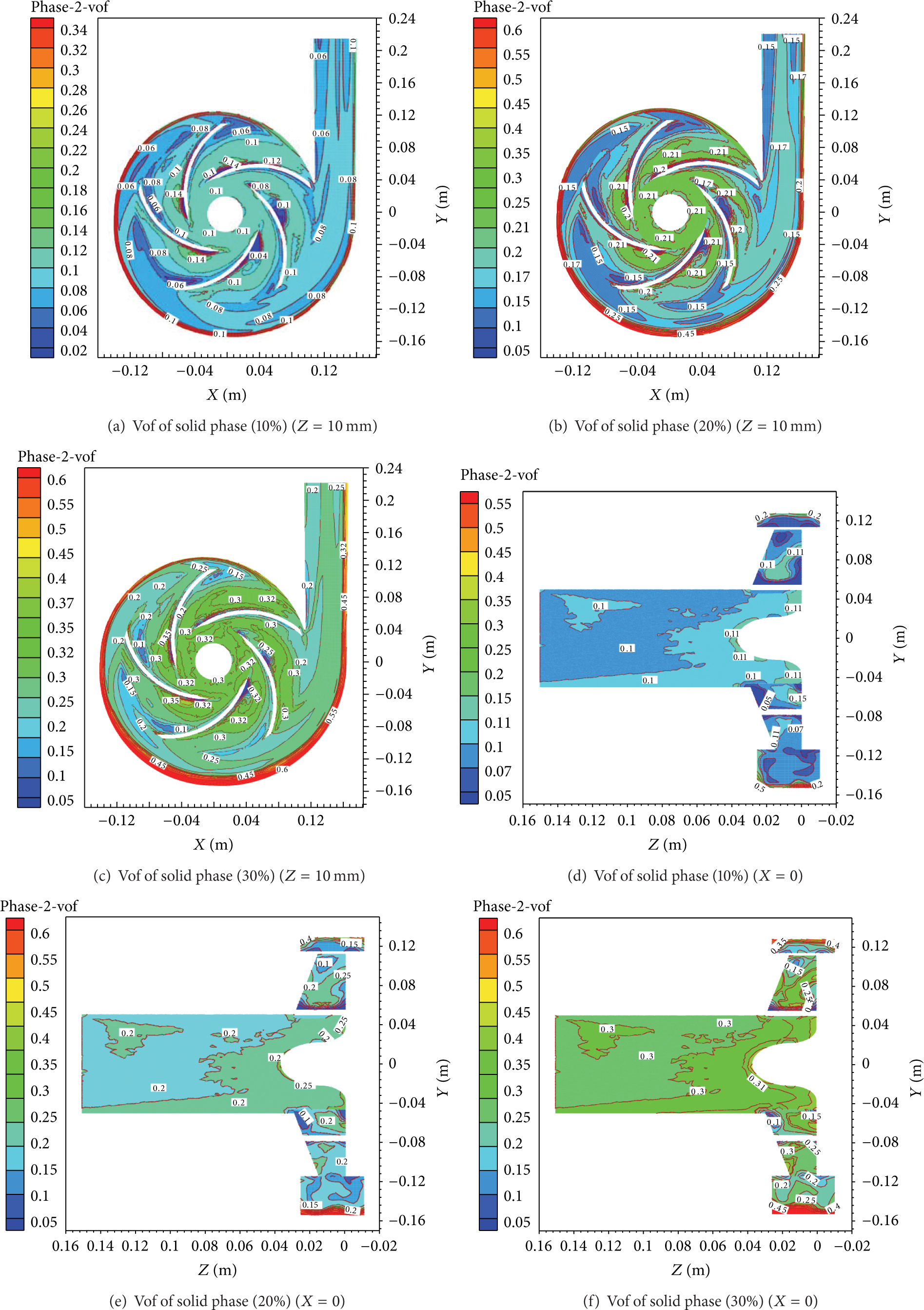
Volume fraction distribution of solid phase.
5. Conclusions
The erosion wear in slurry pumps has been identified as a major problem during transportation of slurry as it affects the equipment performance and reduces its reliability and operation life. Therefore, it is very important to predict the wear-corrosion of flow passage component by analyzing slurry flow characteristics through a centrifugal slurry pump. Although a lot of experimental and numerical research on the flow in a centrifugal pump has been conducted and many significant results have been achieved [29–36], there are still many doubts to resolve, especially for the low specific speed solid-liquid centrifugal slurry pump with complex internal structure. For example, the iteration convergence problem caused by complex internal structure and high rotational speed of pump is always a problem for numeral simulation researchers makes it difficult to get accurate results for numerical simulation or a denser grid need to be provided which will waste more computing resource. In the present study, the combination of three measures of dynamic underrelaxation factor adjustment, step method, and rotational velocity control means according to residual curves trends of operating parameters was used to improve the numerical convergence. Numeral simulation of 3D turbulent flow in a low specific speed solid-liquid centrifugal pump was performed, and the results showed that the improved solution strategy is greatly helpful to the numerical convergence. Moreover, the calculated results gave the main region of the abrasion of the impeller and volute casing and improve the hydraulic design of the impeller in order to decrease the abrasion and increase the service life of the pump.
Conflict of Interests
The authors declare that there is no conflict of interests regarding the publication of this paper.
Footnotes
Acknowledgment
This work is supported financially by the National Natural Science Foundation of China under Grant no. 51225601.