
Abstract
Carbon fiber-reinforced plastic (CFRP) is a lightweight material that can potentially replace structural steel components in automobiles. The hole-clinching process is a mechanical clinching technique for joining brittle or low-ductility materials, such as CFRP, with ductile materials. In this study, the influence of tool shape on the hole-clinching process for CFRP and SPRC440 was investigated using FE-analysis and experiments. The parameters of the tool shape investigated were the punch corner radius and the punch diameter. The geometrical interlocking shapes of hole-clinched joints were characterized by neck thickness and undercut. Based on the desired joint strength of 2.5 kN, hole-clinching tools were designed on the basis of the relationship between joint strength and geometrical interlocking. FE-analysis and hole-clinching experiments were performed with the designed hole-clinching tools to investigate the geometrical interlocking shape as well as joinability, including neck fracture, undercut, and hole expansion, resulting from changes in tool parameters. Joint strength was evaluated to verify the effectiveness of hole clinching by a single lap shear test.
1. Introduction
Recent car body design concepts use dissimilar materials, that is, multimaterial design, to reduce weight. Use of carbon fiber-reinforced plastic (CFRP) laminates has especially increased in the automotive industry owing to their low density and good mechanical properties [1–3]. However, the joining of dissimilar materials, such as CFRP laminates with other materials, is still one of the main issues that must be resolved for successful multimaterial design. Spot welding is generally used for joining steel structures because of its low cost and instantaneous production time. For widespread application of CFRP laminates in automotive industry, new joining methods that are similarly instantaneous and cheap are required in order to replace spot welding [4].
Generally, adhesive bonding and mechanical fasteners are used for joining CFRP laminates. Adhesive bonding is suitable for joining any combination of similar or dissimilar materials by surface attachment. However, it requires additional surface treatment and long curing time, which increase production time and cost. In addition, the effects of environmental parameters such as temperature and humidity on the joint properties require careful consideration in adhesive bonding [5–7].
Mechanical fasteners such as bolts and rivets are also used to join CFRP laminates [8–11]. Bolts and rivets provide high joint strength and stability for varying environmental parameters. However, the production time required for mechanical fasteners is longer than that for spot welding. A self-piercing rivet (SPR) has been widely used to replace spot welding for joining dissimilar metals such as aluminum alloys and high-strength steel. SPR is not suitable for joining CFRP laminates, however, because the CFRP laminates may be easily damaged at the site of the hole pierced by SPR during the joining process. Moreover, the production costs of these mechanical fasteners are high owing to the requirement of additional joint elements such as bolts and rivets [12].
Recently, technical and economical limitation of traditional joining method in automotive industry leads the new attempts of joining for composite with metals. Bolle et al. [13] investigated the feasibility and mechanical properties of ultrasonic spot welding of AA5754 with CF-PA66 (polyamide 66), which was thermoplastic composite. Bergmann and Stambke [14] studied the joinability of DC01 and PA66 by using laser. Goushegir et al. [15] investigated mechanical properties of friction spot joining of AA2024 with CF-PPS (polyphenylene sulfide). Recent investigations on new joining techniques are focused on joining by heat sources, such as laser, ultrasonic, and friction. Thus, these techniques are only available for joining of thermoplastic composite.
Hole clinching is a mechanical clinching method for joining brittle materials with ductile materials [16]. In the hole-clinching process, a lower sheet with a hole that is made of brittle material such as CFRP laminate is placed above a die, beneath an upper sheet of ductile material, as shown in Figure 1. The upper sheet of ductile material is indented into the cavity between the die and the lower sheet of brittle material. Geometrical interlocking between the upper and lower sheets is plastically formed by the punch and the die. Because hole clinching does not require additional joint elements, it is possible to reduce the production cost in comparison to other methods.

Schematic drawing of the hole-clinching process.
It is well known that geometrical interlocking is influenced by the shapes of the clinching tools. Oudjene et al. [17, 18] have employed design of experiment techniques and FE-analysis to optimize eight parameters related to clinching tool shape. Lambias and Ilio [19] optimized clinching tools by FE-analysis and artificial intelligence techniques. Lee et al. [20] have proposed a clinching tool design method using an analytical model and Box-Behnken methods. Previous studies showed that parametric study of clinching tool shape is necessary to obtain sufficient joint strength.
The purpose of this study is to investigate joinability of CFRP laminates and SPRC440 by the hole-clinching process. The influence of tool shape on geometrical interlocking was studied by FE-analysis and experiment. Punch corner radius and punch size are selected as the parameters of the tool shape. The geometrical interlocking shapes of the hole-clinched joints are characterized by neck thickness and undercut. Based on the results of FE-analysis, a hole-clinching experiment was performed to evaluate joinability. Joint strength was also evaluated using the single lap shear test to verify the effectiveness of hole clinching as a joining method for automobile body materials.
2. Numerical and Experimental Preparation
2.1. Material Properties
In this study, the hole-clinching process for joining CFRP and SPRC440 was studied by FE-analysis and experiment. SPRC440, a high-strength steel used in automobile bodies, with a thickness of 1.6 mm was used as ductile material in the hole-clinching process. A plain-woven preimpregnated fabric (prepreg), HD plain weave 3 K from Mitsubishi Rayon Co., was used for the CFRP laminate. The prepreg was stacked with the desired thickness 1.2 mm and cured at a pressure of 50 bar by the hot-press molding process. Figure 2 shows the hot-press molding machine and curing cycle of thermoset epoxy resin in CFRP prepreg.

Hot-press molding machine and curing cycle of thermoset epoxy resin.
Figure 3(a) is the cross-section of CFRP laminates after hot-press molding. The void was observed at matrix resin between CFRP laminates. This void was one of the reasons to reduce the mechanical properties and to cause the delamination of CFRP laminates. For structural applications, the void content of CFRP laminate should be controlled to be less than 5% of the entire volume in the manufacturing process [21]. According to ASTM D3171 [22], the matrix resin was removed by chemical digestion. The mass and the volume of matrix resin and reinforcement were measured before and after chemical digestion, as shown in Figure 3(b). The void content of the CFRP laminate was calculated using

Here, V is volume percentage, and the subscripts r, m, and v indicate the matrix, reinforcement, and void of the CFRP laminate, respectively. M i and M f are the mass of CFRP laminates before and after chemical digestion, respectively. The density of the reinforcement, matrix, and CFRP laminate, indicated by ρ r , ρ m , and ρ c , are evaluated according to ASTM D792 [23]. The void content was 1.47±0.17% of the entire volume of CFRP laminate used for the specimen in this study. The results of the experiments are listed in Table 1.
Volume percent of resin, fiber, and void in CFRP laminates.


Evaluation of the void content of CFRP laminate by chemical digestion.
The mechanical properties of the CFRP laminate and SPRC440 were evaluated by tensile tests, as shown in Figure 4. According to ASTM D3039 [24], the tensile test of the CFRP laminates was performed for the 0° and 45° fiber directions, as shown in Figure 4. The elastic moduli of the CFRP laminates were found to be 175.3 GPa and 31.2 GPa for the 0° and 45° fiber directions, respectively. Table 2 lists the mechanical properties of the CFRP laminate and SPRC440 determined by tensile tests.
Mechanical properties of CFRP laminates and SPRC440.


Tensile test of SPRC440 and CFRP laminates.
2.2. FE-Modeling of the Hole-Clinching Process
In this study, the influence of tool shape on geometrical interlocking in the hole-clinching process was investigated using the commercial FE-code DEFORM 2D. Figure 5 shows the FE-model of the hole-clinching process for joining CFRP and SPRC440. SPRC440 was modeled as a plastic material because it deformed as the upper sheet to form geometrical interlocking with a high strain state. Although CFRP laminates are anisotropic, the material behavior is assumed to be isotropic elastic-plastic material for reducing computational time through simplification. In addition, the mechanical properties of CFRP laminates along the 45° direction were used in FE-analysis for simulating partial deformation of the CFRP by the reaction force due to the indention and spreading of upper sheet during hole clinching. Considering the shape of stress-strain curves, the flow stress of CFRP for 45° direction was expressed by bilinear model. The respective friction coefficients between CFRP and SPRC440, between SPRC440 and the clinching tools, and between CFRP and the clinching tools were found to be 0.3, 0.1, and 0.3 from a flat friction test, as shown in Figure 6. The role of the holder was to prevent backward extrusion and increased hydrostatic pressure in the upper sheet [25]. The holder was operated by a coil spring with 0.6 kN initial force and a stiffness of 0.67 kN/mm.

FE-model of the hole-clinching process for CFRP laminate and SPRC440.

Apparatus of the flat friction test.
During the hole clinching, the upper sheet was highly deformed at neck to make geometrical interlocking. Also, the damage is mainly accumulated at neck. Thus, the mesh density of materials should be adjusted to describe the deformation behavior and damage accumulation of materials. In FE-models of hole-clinching process, the mesh density near the neck of upper sheet was higher than other parts. When constructing mesh of upper and lower sheet, relative element size at neck is smoothly decreased up to 10 times smaller than materials under holder part.
The range of shape parameters of clinching tools can be determined by the relationship between joint strength and geometrical interlocking. Ahn et al. [16] have proposed a relationship between geometrical interlocking and joint strength. In the hole-clinching process, the joint strength, F S , is dependent on the neck thickness of the upper sheet in the shear mode loading condition as follows:

Here, k f is the fracture shear stress of the upper sheet, as 334.9 MPa. A f is area of the fractured joint. D P and T N are the punch diameter and neck thickness, respectively. For the given joint strength of 2.5 kN, multiple solutions to (2) are possible, as shown in Figure 7. The lower limit of D P was determined from the geometrical relationship in the control volume (V c ) for hole clinching, as shown in Figure 5. The geometrical interlocking is formed when the volume of the punch (V p in Figure 5) and upper sheet (V u in Figure 5) is larger than the control volume as follows:

From the relationship in control volume before and after hole clinching, the punch volume can be determined as the following equation:
Here, S is punch stroke. Thus, the minimum punch stroke, S min , which is required to make geometrical interlocking, can be determined as the following equation:


Solutions obtained for the relationship between joint strength and geometrical interlocking with the desired strength of 2.5 kN.
In Figure 1, the maximum punch stroke, Smax, is determined from the following equation:

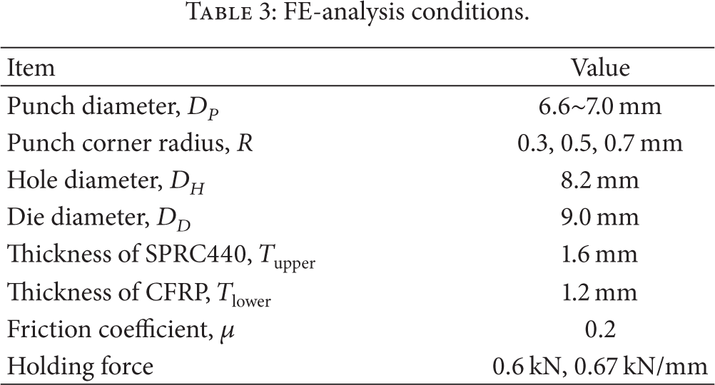
For D P less than 6.4 mm, geometrical interlocking could not be formed according to (5) and (6). There is no theoretical upper limit of D P . However, when D P is increased, the hoop stress around the neck of the upper sheet is increased. This may cause neck fracture of the upper sheet before the upper and lower sheets are geometrically interlocked. The FE-analysis conditions are summarized in Table 3.
FE-analysis conditions.
3. Numerical and Experimental Results
3.1. Influence of Punch Corner Radius on the Geometrical Interlocking
The FE-analysis was performed to investigate the influence of punch corner radius on geometrical interlocking. In the clinching process, geometrical interlocking is strongly influenced by punch corner radius. [17, 20] The initial deformation of the upper sheet is particularly influenced by the punch corner shape. The upper sheet is initially indented through the narrow clearance as in a deep-drawing and ironing process. Sharp punch corners prevent draw-in of the upper sheet, which causes deformation of material around joint, as shown in Figure 8. However, in the hole-clinching process, only the upper sheet is deformed; it is not supported by the lower sheet. Therefore, the hydrostatic pressure which helps with geometrical interlocking at high strain state without fracture is less than that in the conventional clinching process. This means that sharp punch corners may cause neck fracture of the upper sheet during the indentation step.

Draw-in of the upper sheet in hole-clinching process using punch with D P = 6.8 mm; R = 1.0 mm.
According to Lee et al. [26] and Roux and Bouchard [27], neck fracture in the clinching process is caused by ductile damage of the upper sheet. This means that ductile damage can be used for prediction of neck fracture in FE-analysis of the hole-clinching process designed in this study. Figure 9 shows a comparison of neck fracture of a hole-clinched joint and the damage distribution of the neck from the FE-analysis. Ductile damage, D, is calculated by the normalized Cockcroft and Latham's equation as follows:
Here,

Comparison of FE-analysis and experiment for neck fracture in the hole-clinching process using punch with D P = 7.0 mm, R = 0.3 mm.
Figure 10 shows the effect of punch corner radius, R, on geometrical interlocking. The results of the FE-analysis showed that a sharp punch corner radius increased the undercut. When R = 0.3 mm, the undercut had the highest value of 0.094 mm. However, the maximum damage value was 1.89, as shown in Figure 11(a), which is larger than the critical damage value of 1.61. It is expected that neck fracture occurs when R = 0.3 mm. The damage value at the neck decreased to 1.00 when the punch corner radius was increased from 0.3 to 0.7 mm, as shown in Figure 11(b). However, increasing R results in a decrease in the punch volume and eventually a decrease in the undercut, according to (3). Therefore, a slight undercut of 0.002 mm was formed.

Effect of punch corner radius on geometrical interlocking.

Geometrical interlocking shape and damage value distribution for various punch corner radii.
Punch corner radius also influences the neck thickness. When R = 0.3 mm, the neck thickness is decreased to 0.584 mm because of tensile stress at the neck of the upper sheet, which causes necking. The upper sheet is constrained by the holder and drawn into the die cavity by the punch in the initial step of hole clinching, so the tensile stress is applied to the upper sheet. A sharp punch corner increases tensile stress by concentration of deformation. Although a blunt punch corner reduces damage accumulation, it also affects the hole diameter of the lower sheet. Figure 12 shows the metal flow for radial direction in a hole-clinched joint at the initial indentation step of hole clinching. As the upper sheet is indented into the die cavity, the upper sheet material near the punch corner flows in the radial direction and pushes the lower sheet, which causes expansion of the hole diameter, leading to an increase in the clearance between the punch and the hole in the lower sheet. Thus, when R = 0.7 mm, the neck thickness is increased to 0.821 mm, greater than the desired neck thickness, by the increase in clearance of about 0.021 mm.

Material flow of the upper sheet and lower sheet for radial direction at the initial step of the hole-clinching process.
3.2. Influence of Punch Diameter on Geometrical Interlocking
Increasing the size of a hole-clinched joint is an efficient way of increasing joint strength, because the fracture area is dependent on the punch diameter according to (2). However, the hoop stress increases with the increase in the punch diameter, which may split the bottom material of a hole-clinched joint during spreading into die cavity, as shown in Figure 13. A coining effect strongly affects the thin bottom of the joint in the spreading step of the hole-clinching process. This means that the forming load is dramatically increased with an increase in forming area. The forming load is limited by the maximum load capacity of the clinching machine, which was set to 100 kN in the FE-analysis.
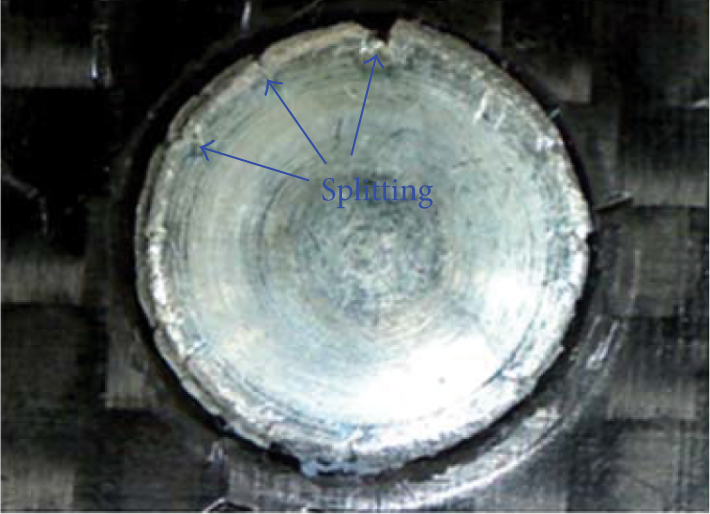
Splitting of the bottom material in a hole-clinched joint.
Figure 14 shows the effects of punch diameter on geometrical interlocking. For small punch diameter, large neck thickness is required to obtain the desired joint strength. An increase in clearance is necessary to form the larger neck thickness, which also increases the forming volume required to form the undercut. Thus, when D P = 6.6 mm, a slight geometrical interlocking between the upper and the lower sheets is formed with an undercut of 0.057 mm and neck thickness of 0.772 mm. When D P is larger than 6.8 mm, a sufficient undercut was formed to fasten the lower sheet. The increase on punch diameter corresponds to an increase in the forming volume of material and a decrease in clearance. The undercut increased to 0.215 mm and the neck thickness decreased to 0.712 mm when the punch diameter was changed from 6.6 mm to 6.8 mm. However, when D P = 7.0 mm, the neck thickness increased to 0.732 mm and undercut decreased to 0.184 mm. During the spreading step of hole clinching, the bottom material is squeezed to fill the die cavity. This material flow pushes the lower material and expands the clearance between the punch and the hole. Thus, the increased clearance causes material flow that does not form the undercut and increases the neck thickness. Figure 15 shows the damage distribution around the neck of the upper sheet. When D P = 7.0 mm, the maximum damage value was 1.46, which is similar to the allowable damage value. This indicates that the increase in punch diameter may cause neck fracture during hole clinching. In addition, the high damage value is distributed at the end of the undercut because the hoop stress is increased with the increase in punch diameter.

Effect of punch diameter on geometrical interlocking.

Damage distribution around the neck of the upper sheet for different punch diameters.
3.3. Results of the Hole-Clinching Experiment
Based on the results of FE-analysis, a hole-clinching experiment was performed to verify the influence of tool shape on geometrical interlocking. Figure 16 shows the clinching machine with 100 kN load capacity. The hole in the CFRP laminate was drilled with polycrystalline diamond (PCD) tools to prevent delamination. The centers of the punch and die should be in alignment with the center of the hole to obtain a successful hole-clinched joint. If the punch and die are misaligned with the center of the hole, deviation of the neck thickness would occur, or the neck would be fractured in a severe case, as shown in Figure 17(a). During the hole-clinching process, the CFRP laminate is dragged into the die by the friction between the SPRC440 and CFRP laminate. Misalignment causes delamination of CFRP laminate by severe dragging, as shown in Figure 17(b). In this study, a fixture was used to control the alignment of the tools and hole, as shown in Figure 16.

Hole-clinching machine with 100 kN load capacity and fixtures.

Defects in a hole-clinched joint caused by misalignment of the center of the tool and hole.
Figure 18 shows the geometrical interlocking shape of a hole-clinched joint as compared with FE-analysis. The experimental results were in good agreement with the FE-analysis within a dimensional error of 4.35%. Dragging of CFRP laminate was observed in all experimental cases. The deformed shape was similar to that in the FE-analysis. This shows that the use of the elastic-plastic material model for CFRP laminate is suitable for describing the deformation behavior of CFRP laminate in the hole-clinching process.
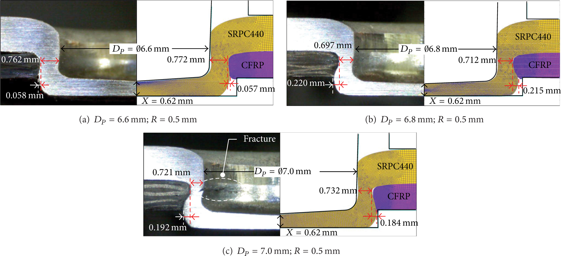
Comparison of geometrical interlocking in experiment and FE-analysis.
When D P = 6.6 mm, slight geometrical interlocking was formed with an undercut of 0.057 mm and neck thickness of 0.81 mm. The hole in the lower sheet was expanded from 8.20 mm to 8.21 mm. The CFRP laminate around the hole was elastically deformed by the hole expansion and compressed SPRC440 as in a shrink fit. Even though the hole-clinched joint had insufficient undercut, it provided remarkable strength owing to the effective shrink fit. When D P = 6.8 mm, the CFRP laminate and SPRC440 were interlocked with an undercut of 0.22 mm and neck thickness of 0.69 mm. The hole expansion increased to 0.04 mm because the SPRC440 pushes the CFRP laminate while forming the undercut. This hole expansion results in an increase in clearance, which also increases the neck thickness. When D P = 7.0 mm, partial neck fracture was observed at the location of the maximum damage value found in the FE-analysis. This may be due to the deformation of the upper sheet being slightly concentrated at one side of the neck by the misalignment between the tools and specimen. This result showed that the ductile damage criterion was suitable for predicting neck fracture of the upper sheet in the FE-analysis. However, the damage value was evaluated as 1.46 which was smaller than 1.89 of critical damage value in FE-analysis, even though neck fracture was occurred in experiment. During FE-analysis of hole-clinching process, damage accumulation may be underestimated due to remeshing around the neck of upper sheet. Thus, the investigation of the effect of element size and remeshing criteria on damage accumulation at neck of upper sheet is required for predicting the neck fracture in hole-clinching process in future work.
Effect of tool shape on deforming behavior of sheets in hole-clinching process was summarized in Figure 19. Hole clinching with sharp punch corner radius showed sufficient geometrical interlocking. But necking tendency and neck fracture were observed at hole clinching with sharp punch corner radius in FE-analysis and experiment. Hole expansion was increased with increase in punch corner radius. Large punch diameter was helpful for increasing geometrical interlocking of hole-clinched joint but effect of punch diameter was limited by neck fracture. Undercut and hole expansion were increased with increase in punch diameter. But neck of upper sheet showed the necking tendency when punch diameter was increased in FE-analysis. Also, the same case of hole-clinched joint with large punch diameter showed partial neck fracture in experiment.
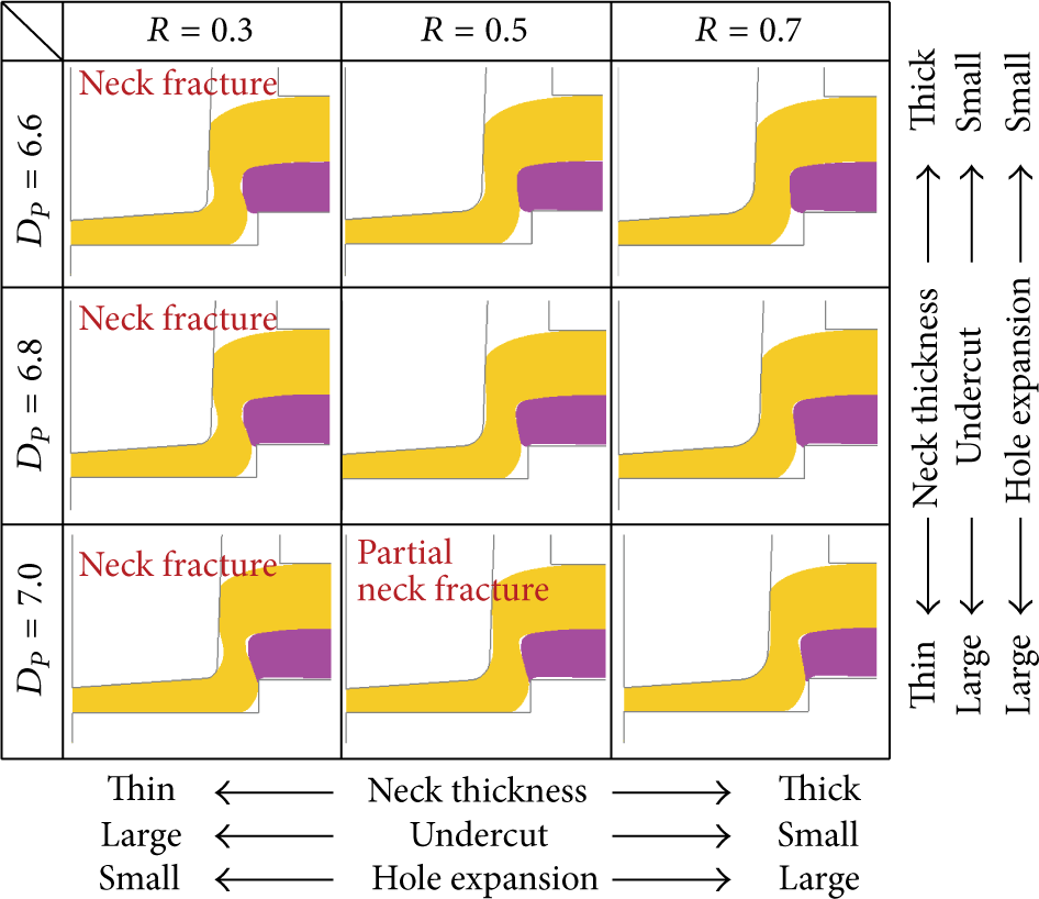
Effect of tool shape on deforming behavior of sheet in hole-clinching process.
4. Hole-Clinching Joint Strength
Joint strength was evaluated to verify the effectiveness of hole clinching for an automotive joint using the single lap shear test. The dimensions of the single lap shear specimen are illustrated in Figure 20. SPRC440 and CFRP laminate, 25 mm in width and 125 mm in length, were overlapped in a 25 mm × 25 mm area and joined by hole clinching. The single lap shear test was carried out using a universal material testing machine with a load capacity of 100 kN. The specimen was fixed with an additional sheet to reduce the bending moment at both ends of the specimen overlap, as shown in Figure 20.

Dimensions of a single lap shear specimen.
Effect of tool shape on the strength of hole-clinched joint was evaluated by the fracture load of the specimen. The fracture load of specimen depended on the failure mode, such as neck fracture mode and button separation mode. In neck fracture mode, the fracture load of specimen was influenced by deviation of neck thickness, necking, or damage accumulation of neck. Button separation mode usually was caused by insufficient geometrical interlocking or failure of lower sheet in hole-clinching process. After the single lap shear test, the failure mode of specimen was observed and analyzed from the aspect of the influence of these factors on the fracture load of hole clinching.
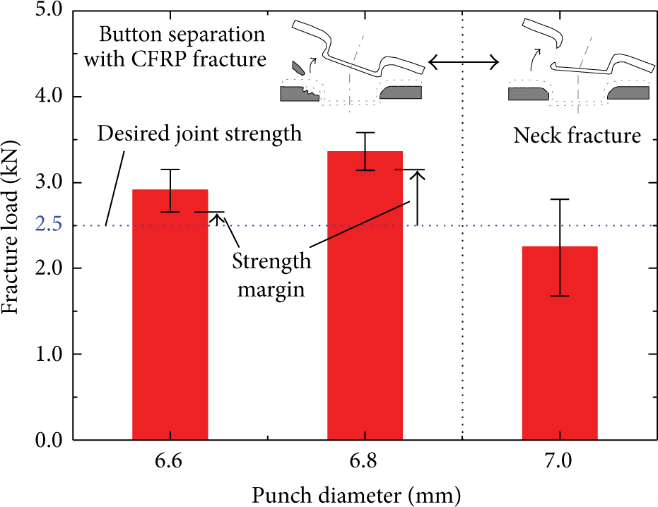
Figure 21 shows the load-displacement curves from the single lap shear test. For the hole-clinched joints with D P = 6.6 mm and 6.8 mm, the average maximum fracture loads were 2.91±0.24 kN and 3.36±0.22 kN, which is greater than the desired joint strength of 2.5 kN. The fracture load of specimen was increased with increase in punch diameter. But the hole-clinched joint with D P = 7.0 mm was fractured at a load of 2.25±0.56 kN. The failure mode of the specimen with D P = 7.0 mm was the neck fracture mode, as shown in Figure 22(c), because the neck was partially fractured in the hole-clinching process, as shown in Figure 18(c).

Load-displacement curves from the single lap shear test.
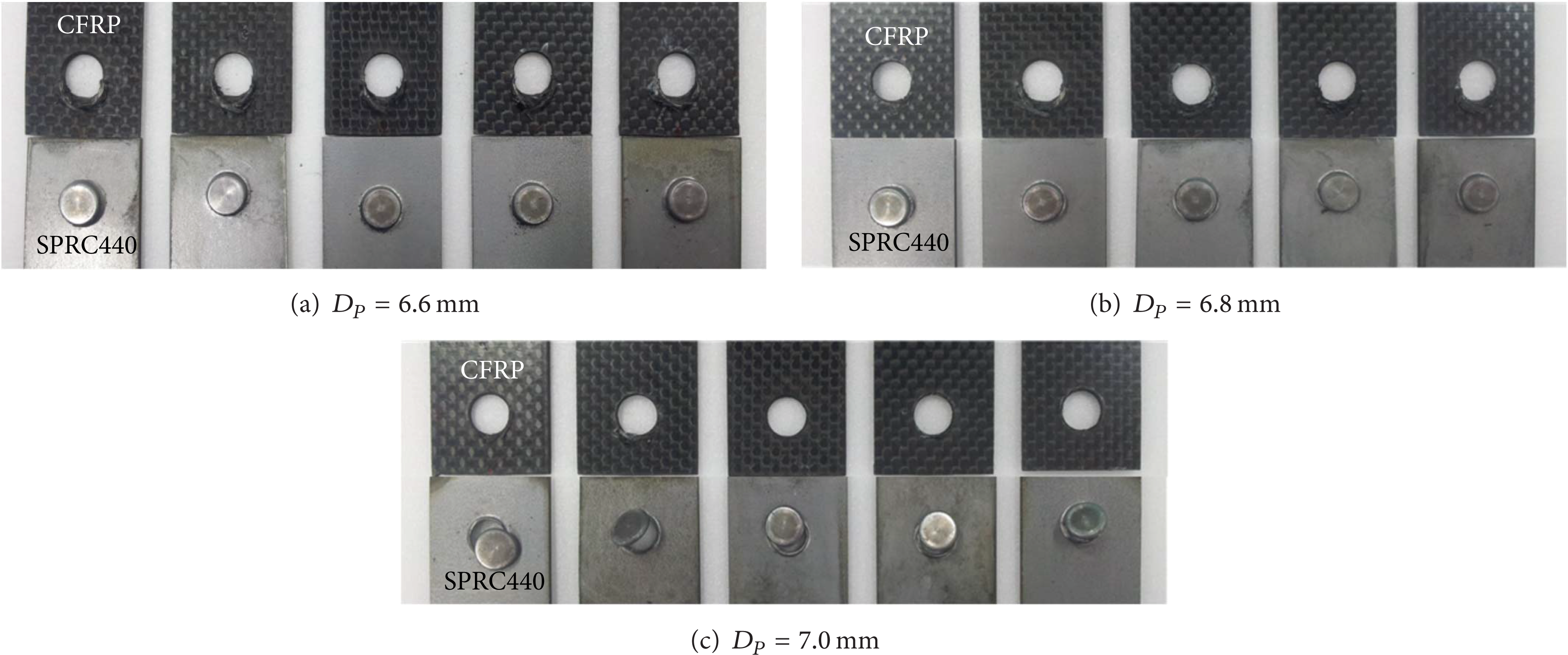
Failure modes of hole-clinched joints.
The failure modes of the hole-clinched joints with D P = 6.6 mm and 6.8 mm were button separation with failure of the CFRP laminate around the joint, as shown in Figures 22(a) and 22(b). During the single lap shear test, a bearing load was applied at the hole in the CFRP laminate. The SPRC440 button was separated when the CFRP laminate at the hole was fractured. During the single lap shear test, the tensile load acting at hole of CFRP laminate induced the bending moment. As tensile load was increased, the CFRP laminate was partially fractured by this bending moment. The scattering of fracture load of specimen with D P = 6.6 mm and 6.8 resulted from partial damage of CFRP laminates during the hole clinching. Thus, the damage of CFRP, such as dragging and delamination should be minimized in hole-clinching process design step. Also, the drilling without delamination of CFRP laminate was one way to reduce damage of CFRP.
The specimen with D P = 6.8 mm had higher joint strength than that with D P = 6.6 mm because of the effect of hole expansion and sufficient geometrical interlocking. However, the undercuts were formed with dragging of the CFRP laminate. According to Ueda et al. [28], severe dragging induces the delamination of CFRP laminate. This implies that severe dragging would be one of the reasons for the reduction in joint strength in the button separation mode with CFRP laminate failure. Although the hole-clinched joint with D P = 6.6 mm had an insufficient undercut of 0.057 mm, its fracture load was greater than the desired joint strength. As mentioned above, an effective shrink fit is formed in a hole-clinched joint by hole expansion in the CFRP laminate. The fracture load of the hole-clinched joint with D P = 6.6 mm shows that the effective shrink fit provides sufficient strength to endure the external load.
The effect of tool shape on fracture load and failure mode of specimen was summarized in Figure 23. The fracture load of specimen depended on the size of hole-clinched joint. And the button separation mode of specimen with failure of CFRP laminates showed higher fracture load than neck fracture mode. When punch diameter was increased, the failure mode of specimen changed from button separation mode to neck fracture mode with dramatic drop of fracture load. Hole clinching with large punch diameter had more strength margin than small punch diameter. Bigger strength margin of large punch diameter indicated that the fracture load of joint was not sensitive for noise factors, such as deviation of neck thickness and void in CFRP. Thus, in view point of robustness design of hole clinching for automotive joint, even though small size tools are easy to join SPRC440 and CFRP laminates without neck fracture in hole-clinching process, the larger punch diameter is recommended for assuring the sufficient joint strength against noise factors. This design rule is available until neck fracture mode occurred.
Effect of tools shapes on the joint strength and failure modes of hole-clinched joint.
5. Conclusions
In this study, the influence of tool shape on geometrical interlocking was investigated in the hole-clinching process for CFRP laminate and SPRC440. A hole-clinching process was designed, and the ranges of design parameters were determined for a desired joint strength of 2.5 kN. Based on the FE-analysis and experiments performed in this study, the following conclusions can be drawn.
(1) Punch corner shape influences the necking of the upper sheet and hole expansion in the lower sheet. A sharp punch corner induced a concentration of deformation at the neck of the upper sheet, which decreased the neck thickness owing to necking of the upper sheet. A blunt punch corner reduced the damage value at the neck but expanded the hole in the lower sheet. The neck thickness was increased owing to hole expansion because the neck was formed in the clearance between the punch and expanded hole. Because the forming volume required to form the undercut was increased by hole expansion, the materials were not geometrically interlocked owing to the lack of material volume.
(2) The joint strength increases in proportion to the punch diameter, which increases the fracture area of hole-clinched joints. For a small punch diameter, larger neck thickness was required to obtain the desired joint strength, and, therefore, the clearance should be increased. However, the increased clearance prevented geometrical interlocking owing to the lack of material volume to form the undercut. For a large punch diameter, sufficient undercut was formed for geometrical interlocking because the required neck thickness decreased. However, the excessive punch diameter caused a decrease in neck thickness while expanding the hole.
(3) Compared with results of the hole-clinching experiment, the FE-analysis described the deformation of CFRP laminate and SRPC440 well, within a dimensional error of 4.35%. The dragging of CFRP laminate was observed in the cross-sections of all hole-clinched joints. The hole-clinched joints without neck fracture had a joint strength greater than the desired value of 2.5 kN. The hole-clinched joint with insufficient undercut also had a joint strength greater than the desired value owing to the effect of a shrink fit caused by hole expansion in the CFRP laminate. These results show that hole clinching is suitable for joining CFRP laminates and SRPC440 in automotive joints.
(4) The failure mode of the hole-clinched joints was the button separation mode in the CFRP laminate. Hole-clinching tools should be designed to reduce dragging of CFRP laminate, as delamination of CFRP laminate is caused by severe dragging. Although the reduction of dragging decreased the undercut, it is possible to compensate for the decrease in geometrical interlocking through effective shrink fit.
Conflict of Interests
The authors declare that there is no conflict of interests regarding the publication of this paper.
Footnotes
Acknowledgment
This work was supported by the National Research Foundation of Korea (NRF) Grant funded by the Korea government (MSIP) (no. 2012R1A5A1048294).