
Abstract
Traditional simulation mechanisms are unable to meet the simulation requirements of spacecraft launcher in low-gravity environment, like in the Moon. Based on the advantages of wire-driven parallel mechanism, a 6-DOF low-gravity environment simulation device with eight wires is designed in this paper. Firstly, the configuration and dimensional design of this wire-driven parallel mechanism are carried out. To operate and control the wire-driven parallel mechanism, a force distribution algorithm is introduced and the workspace is analyzed. Then, an evaluation index named quality index is established in order to study the performance of the wire-driven parallel manipulator in its workspace and reasonable tension is obtained after analyzing the influence on quality index caused by different wire tension.
1. Introduction
Low-gravity environment simulation technology [1–4] is an important part of space technology, especially in analyzing spacecraft launcher in planets, such as the Moon and Mars, where the gravity is relatively low compared to the Earth's gravity. Thanks to this technology, spacecraft launcher test in low-gravity environment can be conducted on Earth. Currently, available methods for low-gravity environment simulation can be classified into five categories, namely, the free-flight parabolic method, the buoyancy balance method, the rigidity parallel mechanism simulation, the sling suspension method, and the rocket-propelled experiment. Although the free-flight parabolic method is simple to implement, its application is severely limited by shortcomings, such as small load, short simulation time, and high cost, and is not suitable for spacecraft launcher analysis. The buoyancy balance method can establish a broad range of stable low-gravity environments. However, the dynamic performance of the test objects is severely affected by water, which is necessary for the buoyancy balance method. The rigid parallel mechanism simulation developed by the scientist in the former Soviet Union and Japan for spacecraft's docking experiment has good dynamic performance but the workspace is too small for spacecraft launcher simulation. While having large workspace, the sling suspension method has support force along only one direction and cannot accurately simulate the spatial rocket thrust. The sling suspension method is therefore not adopted in launch studies either. The method of rocket-propelled experiment can provide quite accurate situation, but the cost is extremely high. In order to implement spacecraft launching simulation in low-gravity environment, a wire-driven parallel mechanism is designed in this paper.
The wire-driven parallel mechanism consists of two main components [5, 6]: a base frame equipped with motors and winches and a moving platform connected with several wires. The movement of the moving platform is controlled through changing the length of each wire. Because each wire used has light weight and small moment of inertia, the wire-driven parallel mechanism is capable of providing high speed [7] and high acceleration [8] movement of the platform that is capable of high load [9] and has large workspace, all of which are qualities desirable for spacecraft launcher simulation. Combining the real-time control [10], the wire-driven parallel manipulator can realize the spacecraft launcher simulation with relatively low cost. And the launcher simulation experiment can be done many times.
In the 1980s, the wire-driven parallel robot was firstly applied into practice by the NIST (National Institute of Standards and Technology) as a crane, named ROBOCRANE [7]. The wire-driven parallel mechanism then gradually caused the attention of scholars, and the theoretical research about the wire-driven parallel mechanism developed rapidly. Correspondingly, the application fields, such as wind tunnels [11], rehabilitation robot [12], virtual training system [8], lifting equipment, and large radio telescope [13–16], have been expanded greatly. The wire-driven parallel mechanism requires positive wire tension, since wire cannot stand pressure. When considering the principle of “force closure” [17], wire-driven parallel mechanism is similar to multifingered hands’ frictionless crawl in kinematic model. According to the relationship between m, the number of wires, and n, the number of freedoms of the moving platform, Verhoeven [18] divided wire-driven parallel mechanism into three types, that is, IPRMs (incompletely restrained positioning mechanisms, m ≤ n), CPRMs (completely restrained positioning mechanisms, m = n + 1), and RRPMs (redundantly restrained positioning mechanisms, m > n + 1). He further carried out the workspace research considering pull condition and stiffness condition. Barrette and Gosselin [19] introduced the concept of kinetic workspace and determined the workspace boundary of a planar wire-driven parallel mechanism. The workspace problem is quite complex, and there is not a unified and effective method. Although some methods [20–25], such as interval analysis, linear optimization, and the method using convex set analysis, were developed in recent years, none of the methods guarantee the continuous wire tension when the moving platform moves along a continuous path motion in workspace. As a result, wear and vibration problems happen. Besides, those methods are time consuming. Bruckmann et al [22] had made some improvements in the force distribution algorithm. Their algorithms can ensure the continuity of the wire tension, and the computation time is reduced to meet the requirement of the real-time control system. Control technology of the wire-driven parallel manipulator was studied in SACSO project. Lots of research on force feedback control, force-position hybrid control, and other dynamic control technologies has been carried out in WARP and SEGESTA projects. Based on the previous researches, a wire-driven parallel mechanism is proposed for low-gravity environment simulation in this paper, and the design analysis is carried out.
The remainder of this paper is organized as follows. In Section 2, the requirements of low-gravity environment simulation are determined and the kinematics model of an eight-wire-driven parallel mechanism is established. The method to calculate workspace of the parallel mechanism is proposed in Section 3. The parameters of the eight-wire-driven parallel mechanism are determined and the workspace is discussed in Section 4. A quality index is established and the workspace is studied with this index in Section 5. Finally, in Section 6, conclusions and outlook are given.
2. Configuration Design and Kinematic Model
2.1. Requirements of Low-Gravity Environment Simulation
A typical launching process of a return spacecraft from the surface of low-gravity planet consists of four phases as shown in Figure 1. In the taking-off phase between T0 and T1, GNC (guidance and navigation control system) does not work to control and navigate the spacecraft, and successful launch of a return spacecraft therefore depends heavily on the launcher design, which, in turn, is verified by simulations. Because of the difference of the gravity environment between low-gravity planets and Earth, successful launch of a return spacecraft in low-gravity environment cannot be guaranteed without lots of simulation on the launching process. However, the launcher simulation is limited to be conducted on Earth. Then, the simulation device must reflect the low-gravity environment of the return spacecraft's taking-off process as much as possible. Furthermore, this simulation device must be able to simulate different low-gravity environment, engine, and various postures, with enough workspace and real-time motion control.

Launcher process of a return spacecraft.
The above requirements for a low-gravity environment simulation can be concluded as what follows. The low-gravity environment simulation device should achieve 6-DOF motion control and forces output in real time. According to the motion requirement of the taking-off phase on the Moon, the return spacecraft should take off at the acceleration of 1 m/s2 in the first 2 seconds. The attitude deflection of the returning spacecraft must be within 10°. In this paper, the dimension of the moving platforms is 0.4 × 0.4 × 0.2 m and the weight is 10.8 kg. At the same time, the workspace of the low-gravity simulator should contain a cylindrical area of Φ1 × 2 m (red region in Figure 2).
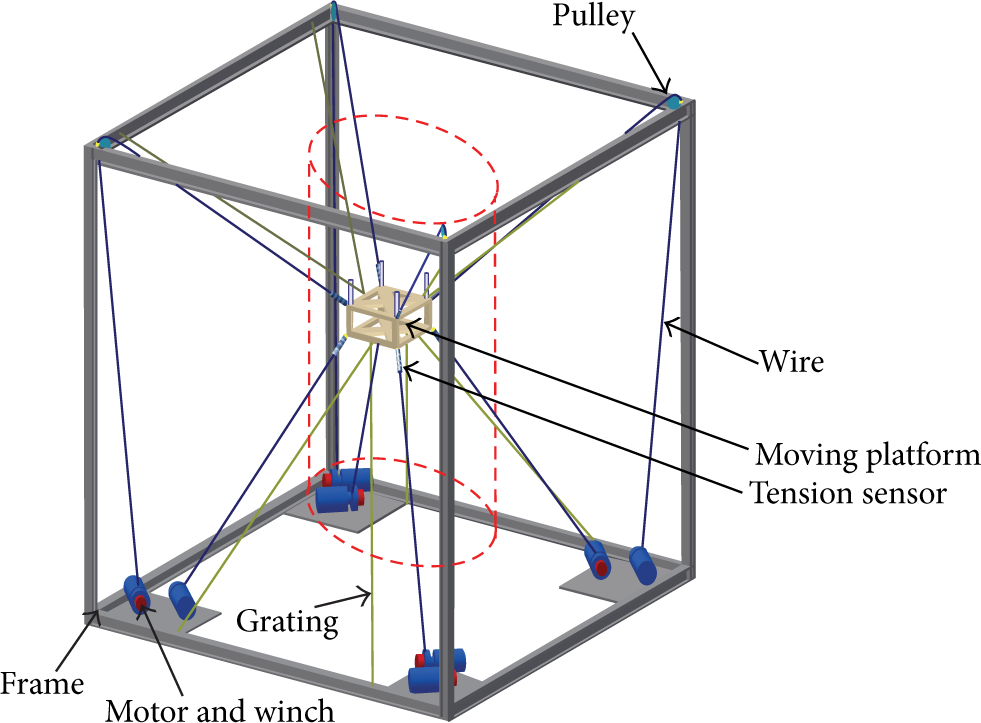
WDPS device with eight wires.
2.2. Configuration Design of the Wire-Driven Parallel Mechanism
In order to achieve 6-DOF motion control of the moving platform, at least seven wires are required [11]. However, the workspace of a seven-wire parallel mechanism is relatively small and the configuration is spatially asymmetric, which will lead to bad isotropic performance. The workspace of a wire-driven parallel mechanism is surrounded by a convex hull which is constituted by the fixed points, and the workspace shape is associated with this convex hull. Both the number of wires and fixed points must be considered during the configuration design of the wire-driven parallel mechanism. For a spacecraft launcher simulation, there is a requirement that external and internal interferences can be applied. To account for the fact, an eighth wire can be conveniently added to introduce the interference force. The eight-wire parallel manipulator is shown in Figure 2. The device is called WDPS (wire-driven parallel simulator for low-gravity environment).
WDPS consists of two main components: a base frame equipped with motors and winches and a moving platform connected together with eight wires. The cuboid moving platform is connected to the winches by wires. The layout of connection points on moving platform is “4–4,” which is located on the eight vertices. The lower four wires are directly connected to the winches, while the upper four wires go through pulleys to be connected to the winches on the bottom. The winches on the bottom are driven by motors to control the length of wire and wire tension. WDPS is designed as a reconfigurable system by using modules with winches and motors. The red cylindrical region in Figure 2 is the smallest envelope of the motion range for the moving platform.
2.3. Kinematics and Force Equilibrium
The mechanism model of WDPS is shown in Figure 3. WDPS can be described using the following vectors and coordinate frames, with i = 1, 2, 3, …, 8.
The coordinate frame κ B is the base frame, and the end-effector frame κ P is connected to the moving platform (Figure 3).
Points B1,…,B8 fixed on the base frame denote the cable connection positions, while P1,…,P8 represent the connection points on moving platform, and l1,…,l8 denote the wire length.

where sφ = sin(φ), cφ = cos(φ), and the rest is similar.

The mechanism model of WDPS.
By the vector loop method, the kinematics of each wire can be established:

Then, the unit vector of the ith wire becomes

The length of the ith wire can be calculated by

The force and torque equilibrium for the platform can be expressed as

Since the forces act along the wires, the force vectors

Hence, the force and torque equilibrium can be written in matrix form as

where

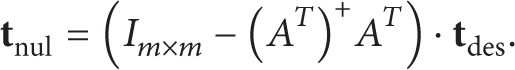
In the following the matrix A T is called structure matrix, which is the transpose of the inverse Jacobian. The matrix A T allows investigation of the existence and quality of the workspace. Traditionally, the workspace of parallel mechanism is a set of poses (position and orientation) which can be achieved without exceeding the joint limits. For wire-driven parallel mechanism, the above condition is not enough. It also requires that each wire be pulled, and the tension should be limited by the maximum tension tmax and the minimum tension t min . The maximum tension is the limit which the wire can withstand, while the minimum tension is required to keep the wire tight. In addition, singularity and wire cross should be avoided. Thus, a condition should be added to (7), which is
2.4. Low-Gravity Environment Simulation
We can write the tension forces in two-part form:
where

If F e is a constant when the platform is moving and F v is a variable according to position and posture of the platform, then the platform should be moving as it is in the low-gravity environment of 1/6 g. Note also that F e can be changed to simulated different low-gravity environment. That is the principle of how WDPS simulates low-gravity environment.
3. Force Distribution
To study the workspace of WDPS, (7) and (10) must be solved. A pose is part of the workspace only if a wire distribution T exists and tmax ≥ f i ≥ t min > 0. Equation (7) gives a problem named “force-close” that requires the solution of (7) to be within certain boundary imposed by inequality (10). To solve the equations, some methods have been proposed like the interval analysis method, the convex set method, and the force-close method. But neither method guarantees continuous wire tension when the platform is moving along a continuous trajectory. In order to obtain a solution with continuous wire tension, the method first proposed by Lafourcade et al. [11] in 2002 is adopted in this paper.
The result of

is the minimal norm solution of (6), where (A
T
)+ is the Moore-Penrose inverse of A
T
. If

To maintain a suitable tension in each wire,
In (15),
Therefore, the workspace of WDPS can be analyzed using the following algorithm based on Monte-Carlo method:
give a position belonging to the convex set of fixed points;
calculate structure matrix A T ;
choose a desired tension
T =
if min(T) ≥ t min and max(T) ≤ tmax, the given position belongs to the workspace. Otherwise, the given position does not belong to the workspace;
next, repeat the above process until all the positions belonging to the convex set of fixed points are calculated.
Obviously, the workspace deduced from the above algorithm is smaller than the usable workspace [14], because
4. Dimensional Design and Workspace
4.1. Dimensional Design
After determining the algorithm to get the force distribution for the wires, it is time to look at the important parameters of WDPS (Table 1). As mentioned in Section 2, the scale of the moving platforms’ dimension is 0.4 × 0.4 × 0.2 m. Also, the length, width, and height of the frame, designed, respectively, by l, w, and h, should be determined. According to the requirements of WDPS, the workspace of the low-gravity simulator should contain a cylindrical area of Φ1 × 2 m. Accordingly, the height of WDPS should be greater than 2 m:

Moreover, considering the space to mount the experiment device and other design conditions, the height of the frame is chosen to be 4 m:

The length and width of the frame affect both the size of the translational workspace and the size of the rotational workspace. The influence is so complex that we cannot get the relationship between the dimension parameters of frame and the translational and the rotational workspace of the platform. However we can get useful information as shown in Figure 4.
The WDPS's parameters: base vector b i and platform vector p i .


The plane parallel mechanism with square platform.
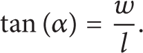
It is obvious that the red configuration in Figure 4 is the maximum rotation angle position of the platform. Because the wire tensions are all positive, it is impossible for the platform to balance the torque applied on the platform by wires without some other torque if the rotation angle of the platform exceeds the red configuration. If β represents the maximum rotation angle of the platform, the length and width of the planar parallel mechanism can be related to β by

where
Naturally, we can draw the image of expression (18) in Figure 5.
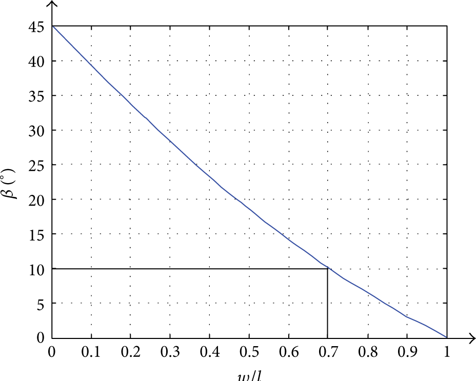
Relationship between the maximum rotation angle β and w/l.
As shown in Figure 5, if the maximum rotation angle β is to be larger than 10°, the ratio of width and length should be less than 0.7. On the other hand, if we want to improve the performance in isotropy of the parallel mechanism, the ratio w/l should be close to 1. It is a wise choice to make the value of w/l fall in [0.6, 0.7]. In order to simplify the determination of width and length of the frame, the ratio w/l is assigned to 2/3. Now, the WDPS frame parameters are
4.2. Workspace
Because of the complexity of the workspace (three translational and three rotational degrees of freedom), it is quite difficult to represent it. The calculation of the wire tensions for a given load will help us to obtain a more precise boundary of the workspace. Supposing that the WDPS is used for simulating the low-gravity environment on the Moon, F e = − (5/6) mg. From Section 2, both the moving platform's dimension is 0.4 × 0.4 × 0.2 m and the weight is 10.8 kg. In addition, the relationship between the length, width, and height of the frame is deduced in Section 4.1. In this section, it is assumed that the length of the frame is 3 m. Then the width of the frame is 2 m. Considering the minimum tension f min = 100 N and the maximum wire tension fmax = 5000 N, if t des = 2500 N and other forces and torques are equal to zero, we can get the translational workspace of WDPS with the platform posture of (0°, 0°, 0°) and maximum rotation angle along Y(10°, 0°, 0°) in Figures 6(a) and 6(b) and, furthermore, the rotational workspace in position (0, 0, 0) in Figure 6(c).

(a) The translational workspace of WDPS with the platform posture of (0°, 0°, 0°). (b) The translational workspace of WDPS with the platform posture of (10°, 0°, 0°). (c) The rotational workspace of WDPS with the platform position (0, 0, 0).
The dimension of the red rectangular box in Figures 6(a) and 6(b) is 1 m × 2 m, and the diameter of the red circle in Figures 6(a) and 6(b) is 1 m. It can be seen that the usable translational workspace of WDPS with a certain attitude angle less than 10° is larger than the required cylinder of Φ1 × 2 m. The diameter of the green circle in Figure 6(c) is 10, which means that the rotational workspace in origin exceeds 10°. In all, the available workspace of WDPS meets the simulation requirement.
Next, it should be checked whether the length and width of the frame are suitable. As shown in Figures 6(a) and 6(b), the translational workspace along cross section (z = 2 m) decreases with the increasing rotation angle along x-axis. So we choose the radius of the largest inscribed circle in this workspace cross section to measure the workspace of WDPS with uncertain length and width satisfying (20). Based on the above discussion, we can draw the relation between the parameter r and l in Figure 7.
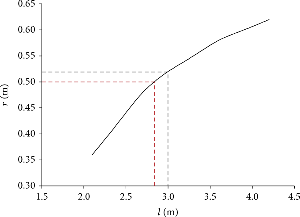
The relation between the parameter r and l (the length of frame).
It is shown that the parameter r increases when the length of the frame grows in Figure 7, and the rate of increase is not constant. The rate of increase decreases at l = 2.8 m and l = 3.7 m. Further, the value of l should be larger than 2.85 m in order to guarantee r ≥ 0.5 m. Considering the manufacture conveniences, we can find that l = 3 m is the appropriate size for the frame.
In the end, parameters of the WDPS's frame are determined, l = 3 m, w = 2 m, and h = 4 m.
5. Quality Index and Tension
5.1. Quality Index
According to the algorithm described in Section 3, the force distribution T can be obtained for a certain posture of the moving platform, and the force distribution changes with the variation of

can thus be used to evaluate the performance of WDPS's workspace.
Since tmax ≥ f i ≥ t min > 0, the range of dσ is [0, 1]. If there is a wire whose tension is tmax or t min in the force distribution, the quality index dσ equals 0 and this pose is on the boundary of the workspace. Such posture is considered to have poor kinematic performance. If the quality index dσ is equal to 1 for a posture, the tension in each wire is (tmax + t min )/2, and the manipulator has good kinematic performance. The quality index dσ can be used as a parameter to evaluate the distance of a posture from the workspace boundary.
According to the above definition of dσ, we can analyze the workspace of WDPS and t des is equal to 2500 N.
From Figures 8(a) and 8(b), it is concluded that the value of dσ in workspace center is larger. It indicates that the force distribution in each wire is far from the tension boundary in workspace center. The platform can move flexibly without worrying about the tension exceeding the maximum or minimum tension limits. In other words, a larger dσ suggests safety and reliability of WDPS. Furthermore, it can be seen that the value of dσ in the red frame region (the theoretical motion region of the platform) is larger than 0.3 for the workspace of the posture (0°, 0°, 0°) and the workspace of the posture (10°, 0°, 0°). The tension in each wire falls in the range of [1715 N,3165 N]. Thus, it can be concluded that the kinematic performance is good in the required red frame region.

(a) The quality index of translational workspace with the platform posture of (0°, 0°, 0°). (b) The quality index of translational workspace with the platform posture of (10°, 0°, 0°).
5.2. Tension
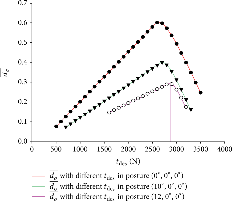
To study the impact of t des on quality index dσ, contour maps are adopted to analyze the quality index with different t des . The resulting dσ distributions in the cross section z = 2 m are shown below (Figure 9).

The quality index with different t des in the cross section z = 2 m with the platform posture of (10°, 0°, 0°).
The value of quality index in the red region changes with the variation of t des . When t des is increased from 500 N to 2500 N, dσ increases constantly. When the tension in each wire is getting closer to 2550 N, the safety of WDPS is improved. However, when t des reaches 3000 N, dσ in center region reduces obviously and it shows a cross-shaped distribution. This means the motion performance varies significantly in a different direction. Meanwhile, it can be inferred that the value of t des affects the size of usable workspace of WDPS.
In order to get more details about the influence of t
des
, a parameter

where ds is the computing unit in the red region, ∫ds is the whole area of the red region, and
As shown in Figure 10, the value of t
des
can affect the quality index and the overall performance in workspace. When t
des
is less than 2600 N, an increase of t
des
can improve the value of
The value of
According to the analysis, we can get the performance parameter of wire-driven parallel mechanism as shown in Table 2.
Final parameters of WDPS.

6. Conclusions
In this paper, a wire-driven parallel mechanism with eight wires for low-gravity environment simulation is presented. This paper first focuses on the configuration and kinematic model design. After determining the configuration and establishing the kinematic model of the device, an algorithm is introduced to solve the problem of force distribution. Then it is proved that the workspace size of this device can satisfy the requirement of the spacecraft launcher simulation. Adopting the defined quality index, the tension in each wire is studied and a reasonable tension interval is obtained to guarantee the good kinematic performance. Ongoing work is to build up this device and implement the real-time control.
Conflict of Interests
The authors declare that there is no conflict of interests regarding the publication of this paper.
Footnotes
Acknowledgment
The research is supported by the National Natural Science Foundation of China (nos. 51205224 and 11178012).