
Abstract
Cold rotary forging is a novel metal forming technology which is widely used to produce the high performance gears. Investigating the microstructure and mechanical property of cold rotary forged gears has a great significance in improving their service performance. In this study, the grain morphology in different regions of the spur bevel gear which is processed by cold rotary forging is presented. And the distribution regulars of the grain deformation and Vickers hardness in the transverse and axial sections of the gear tooth are studied experimentally. A three-dimensional rigid-plastic FE model is developed to simulate the cold rotary forging process of a spur bevel gear under the DEFORM-3D software environment. The variation of effective strain in the spur bevel gear has been investigated so as to explain the distribution regulars of the microstructure and Vickers hardness. The results of this research thoroughly reveal the inhomogeneous deformation mechanisms in cold rotary forging of spur bevel gears and provide valuable guidelines for improving the performance of cold rotary forged spur bevel gears.
1. Introduction
Spur bevel gears, as an indispensable element for momentumtransfer between intersection axes, have been widely used inmechanical, automotive, marine, aeronautical, and astronauticalindustries owing to their high contact ratio, smooth transmission, excellent carrying capacity, and small noise. Cold rotary forging, a promising incremental metal forming process, is widely applied for the fabrication of spur bevel gears, due to the low raw material and energy expenses, remarkable increase in dimensional accuracy and surface finish, and considerable improvement in mechanical properties of products. The working principle of the cold rotary forging process is schematically shown in Figure 1. During the process, the upper die with an inclination angle γ continuously oscillates around the vertical machine axis at a constant rotational speed n. Simultaneously, the lower die pushes the workpiece vertically at a constant feed rate v so as to cause it to be subjected to axial compression. Under the action of the oscillation of the upper die and the axial feed of the lower die, the workpiece is pressed repeatedly and the desired shape will be completed perfectly.

The working principle of cold rotary forging.
Since cold rotary forging is a complicated metal forming process with geometric nonlinear, material nonlinear, and contact nonlinear, several researchers have analyzed the cold rotary forging process in an effort to obtain an in-depth understanding of this process. Summarily, several studies have focused primarily on measuring the pressure distribution in the contact area [1, 2], analyzing the metal flow [3–7] and calculating and verifying the power parameters [8–10] by analytical and experimental methods. In the aspect of FE simulation, Wang and Zhao [11] developed a 3D rigid-plastic FE code programmed in FORTRAN to analyze the cold rotary forging process of a ring workpiece. Liu et al. [12] explored the forming mechanism of the “mushroom shape” effect in cold rotary forging of a cylindrical workpiece based on a 3D rigid-plastic FE model. Hua and Han [13–18] adopted the 3D elastic-plastic dynamic explicit FE method to reveal the deformation mechanisms of cold rotary forging by exploring the effects of the main process parameters on the process. For the research of specific products formed by cold rotary forging, Yuan et al. [19] studied the cold rotary forging process of the knuckle pin using the 3D rigid-plastic FE software DEFORM. Deng et al. [20] simulated the cold rotary forging process of a spur bevel gear and optimized the workpiece geometry. Samołyk [21] achieved the simulation of the complex rocking motion of the upper die in cold rotary forging of an AlMgSi alloy bevel gear.
It should be noted, nevertheless, that the studies in cold rotary forging mentioned above are limited to the macroscopically plastic deformation. And the studies on the microstructure and mechanical properties of cold rotary forged gears are scant. In fact, the microstructure and mechanical properties of cold rotary forged gears can highly affect their service performance. Consequently, the aim of this paper is to reveal the distribution regulars of the microstructure and Vickers hardness in spur bevel gears formed by cold rotary forging so as to provide the theoretical guidelines for improving the performance of the spur bevel gears.
2. Experimental Material and Procedures
The parameters of the spur bevel gear in cold rotary forging are listed in Table 1. The gear material is the low carbon alloy steel of 20CrMnTi, whose chemical composition is listed in Table 2. As a kind of s steel, 20CrMnTi in room temperature is composed of ferrite F and pearlite P, as shown in Figure 2. Figure 3(a) shows the cold rotary forged spur bevel gear. In order to fully illustrate the distribution of the microstructure of the gear, the gear tooth is divided into five specimens from the small-end to the large-end, as shown in Figure 3(b). The transverse sections of the five specimens are shown in Figure 3(c). Before observing the microstructure, the five specimens are pregrinded, polished, and then etched with 4% nital for 10 s–15 s.
Parameters of the specified spur bevel gear.

Chemical composition of 20CrMnTi alloy (wt.%).

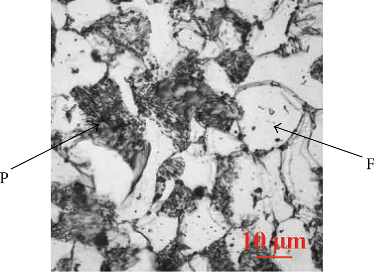
Optical micrograph of 20CrMnTi (×1000).

Spur bevel gear and specimens: (a) spur bevel gear, (b) gear tooth, and (c) specimens.
XP-201 Nikon ECLIPSE polarization microscope is used for taking photomicrographs. With the aim of comprehensively revealing the distribution regular of the microstructure, several specific regions in each transverse section of the gear tooth are chosen to take photomicrographs. As shown in Figure 4, four evenly spaced horizontal lines are chosen in each transverse section. Line (1) is near the addendum of the gear tooth and line (4) is near the dedendum of the gear tooth. On each line, five equally distributed regions are selected to take photomicrographs.

Schematic diagram of the test regions.
In order to investigate the mechanical property of the gear tooth, the Vickers hardness tests are conducted in accordance with ASTM E92 standard [22, 23]. The Vickers hardness tests are carried out at ambient temperature with an applied load of 100 g and a dwell time of 15 s. The values of Vickers hardness (HV) are recorded using a HX-1000TM digital hardness tester equipped with a Vickers diamond indenter. In order to investigate the HV hardness distribution, the same regions which have been taken as photomicrographs are measured (shown in Figure 4).
The FE simulation can provide detailed information about the distribution of strain, strain rate, stress, and the required forming load. These variables are associated with the evolution of microstructure of the spur bevel gear. For the purpose of explaining the relationship between macroscopically plastic deformation and microstructure, the FE simulation of cold rotary forging of a spur bevel gear is carried out by using the commercial rigid-plastic software DEFORM-3D. The FE simulation conditions are summarized in Table 3, which are consistent with the experimental conditions. Figure 5 shows the distribution of the effective strain in the cold rotary forged spur bevel gear.
Summary of the general conditions for the FE model.


The distribution of the effective strain in the cold rotary forged spur bevel gear.
3. Results and Discussion
3.1. Microstructure in the Transverse Section of the Gear Tooth
Because the microstructure distribution in each transverse section is similar, only the photomicrographs of section 4 are presented in this paper. Figure 6 shows the photomicrographs of different regions in section 4, and these photomicrographs correspond to the regions in Figure 4. It can be seen from Figure 6 that the grain deformation is inhomogeneous from the surface to the middle of the tooth owing to the different plastic deformation. In the surface of the tooth, the metal contacts the rigid die and the grains have undergone the severe deformation so that they are obviously stretched in various degrees along the metal flow direction. Particularly, the grains in the dedendum surface, shown in Figure 6(j) and Figure 6(l), are stretched up to fiber and the grain boundaries become blurry. This indicates that in the dedendum surface, the metal produces the most severe plastic deformation. In the middle of the tooth, the grains are slightly stretched. This is because of the fact that the metal in the middle of the tooth produces little plastic deformation and it mainly translates after flowing into the cavity of the die during the cold rotary forging process.

The photomicrographs of different regions in the section 4: (a), (b), and (c) for the region 1, region 3, and region 5 in line (1) of Figure 4; (d), (e), and (f) for the region 1, region 3, and region 5 in line (2) of Figure 4; (g), (h), and (i) for the region 1, region 3, and region 5 in line (3) of Figure 4; and (i), (k), and (l) for the region 1, region 3, and region 5 in line (4) of Figure 4.
3.2. Inhomogeneous Deformation of the Grain
The aspect ratio (L/W: length/width) is an effective way to denote the degree of grain deformation [24, 25]. For comprehensively revealing the inhomogeneous deformation regulars of the grain in the gear tooth, the distribution of the aspect ratio of the grain in the circumferential, radial, and axial direction are analyzed.
3.2.1. Distribution of the Aspect Ratio of the Grain in the Circumferential Direction of Transverse Sections
Figure 7 shows the distribution of the aspect ratio of the grain in the circumferential direction of transverse sections. The x-axis represents the five measuring points in the circumferential direction, as shown in Figure 4. The y-axis represents the aspect ratio of the grain. It can be seen from Figure 7 that for the five different sections, the aspect ratio of the grain has the similar distribution regulars in the circumferential direction of transverse sections. The aspect ratio distribution of the grain is inhomogeneous from the surface to the middle of the gear tooth and it exhibits an obvious U-shaped effect, which can be explained by the inhomogeneous distribution of the effective strain in the FE simulation, as shown in Figure 8. It can be seen from Figure 8 that the effective strain of the surface of the gear tooth is larger than that of the middle of the gear tooth. That is, the metal in the surface of the gear tooth produces the severe plastic deformation and thus the aspect ratio of the grain is much larger. While the metal in the middle of the gear tooth produces the little plastic deformation, thus the aspect ratio of the grain is much smaller. The aspect ratio distribution of the grain coincides with the photomicrographs in Figure 6. It can also be seen from Figure 7 that from the addendum to dedendum of the gear tooth, the aspect ratio distribution of the grain becomes more inhomogeneous in the circumferential direction. Take section 4 (Figure 7(d)), for example, the aspect ratio value of the grain in the addendum surface of the gear tooth is about 2.0, which is merely 1.3 times larger than that in the addendum middle of the gear tooth. The aspect ratio value of the grain in the dedendum surface of the tooth is about 3.71, which is about 2 times larger than that in the middle of the gear tooth. Moreover, from small-end to large-end of the gear tooth, the aspect ratio distribution of the grain also becomes more inhomogeneous in the circumferential direction. The difference value of the aspect ratio of the grain between the surface and the middle of the gear tooth in the small-end is about 0.1–0.6, while the difference value of the aspect ratio of the grain between the surface and the middle of the gear tooth in the large-end is 0.8–2.1.

Aspect ratio distribution of the grain in circumferential direction of transverse sections.

The distribution of the effective strain in each transverse section.
3.2.2. Distribution of the Aspect Ratio of the Grain in the Radial Direction of Transverse Sections
The radial direction of gear's transverse section is the direction from the addendum to dedendum. The distribution of the aspect ratio of the grain in the radial direction of transverse sections is shown in Figure 9. It can be seen from Figure 9(a) that in the surface of the tooth, the distribution of the aspect ratio of the grain is inhomogeneous along the radial direction; that is, the aspect ratio of the grain gradually increases from the addendum to dedendum of the gear tooth. This is because that during the cold rotary forging process, the metal in the surface of the tooth flows difficultly because of the large flow resistance exerted by the die cavity. In particular at the corner of the dedendum, the flow resistance in this area is the largest, so that the severe plastic deformation occurs in the dedendum surface. However, in the middle of the tooth, the distribution of the aspect ratio of the grain is homogeneous along the radial direction and the aspect ratio value of the grain ranges from 1.5 to 2, as shown in Figure 9(b). This is because of the fact that the metal in the middle of the tooth is far from the surface of the die cavity, so that the flow resistance is smaller and the metal can flow into the die cavity homogeneously.

Aspect ratio distribution of the grain in the radial direction of each transverse section.
The distribution regular of the aspect ratio of the grain in the radial direction of transverse sections also coincides with the distribution of the effective strain in the FE simulation, as shown in Figure 8. It can be seen from Figure 8 that the effective strain in the surface of the gear tooth gradually increases in the radial direction and the largest effective strain value locates in the dedendum surface of each transverse section, which indicates that the metal in this area undergoes the largest deformation degree. By contrast, the effective strain distribution in the middle of the gear tooth is relatively small and homogeneous in the radial direction.
3.2.3. Distribution of the Aspect Ratio of the Grain in the Axial Direction of the Gear Tooth
The axial direction of the gear tooth is the direction from the small-end to large-end, as shown in Figure 3(b). The distribution of the aspect ratio of the grain in this direction is also investigated in the present study, as shown in Figure 10. It can be seen from Figure 10 that the distribution of the aspect ratio of the grain in the surface of the tooth is inhomogeneous in the axial direction, that is, the aspect ratio of the grain gradually increases from the small-end to large-end (curves of region 1 and region 5 in Figure 10). However, the aspect ratio of the grain in the middle of the tooth is small and homogeneous in the axial direction (curves of region 3 in Figure 10). The distribution of the aspect ratio of the grain in the axial direction also coincides with the distribution of the effective strain in the FE simulation, as shown in Figure 11.

Aspect ratio distribution of the grain in axial direction of gear tooth.

The distribution of the effective strain in the gear tooth.
It should be note that in Figure 10(a), the aspect ratio values of the grain in regions 3, 4, and 5 decrease from the section 3 to section 5; that is, the aspect ratio value of the grain near the addendum of the large-end is smaller. Figure 11(a) also indicates that the effective strain near the addendum of the large-end is smaller. This illustrates that the little plastic deformation occurs near the addendum of the large-end. The reason for this is that at the end of the cold rotary forging process, the metal in the addendum of the large-end has not filled up the die cavity so as to decrease the forming force. Certainly, it does not affect the final dimensional precision of the gear because the metal in this region will be cut off after the cold rotary forging.
3.3. Inhomogeneous Distribution of the Vickers Hardness
3.3.1. Distribution of the Vickers Hardness in the Circumferential Direction of Transverse Sections
Figure 12 shows the distribution of the Vickers hardness in the circumferential direction of transverse sections. It can be seen from Figure 12 that, for the five different sections, the Vickers hardness has the similar distribution regulars in the circumferential direction of transverse sections. The Vickers hardness distribution is inhomogeneous from the surface to the middle of the gear tooth and it exhibits an obvious U-shaped effect, which is similar to the distribution regulars of the aspect ratio of the grain in the circumferential direction of transverse sections. The reason for this is that, because of the inhomogeneous plastic deformation from the surface to the middle of the gear tooth, the degree of cold work hardening is different. That is, the metal in the surface of the gear tooth produces severe cold work hardening and thus the Vickers hardness is much larger. While the metal in the middle of the gear tooth produces little cold work hardening and thus the Vickers hardness is much smaller. It can also be seen from Figure 12 that from the addendum to dedendum of the gear tooth, the distribution of Vickers hardness becomes more inhomogeneous in the circumferential direction. Take section 4 (Figure 12(d)), for example, the Vickers hardness in the addendum surface of the gear tooth increases about 14% compared with the Vickers hardness in the addendum middle of the gear tooth, but the Vickers hardness in the dedendum surface of the gear tooth increases about 40% compared with the Vickers hardness in the dedendum middle of the gear tooth. Moreover, from the small-end to large-end of the gear tooth, the distribution of Vickers hardness also becomes more inhomogeneous in the circumferential direction. The difference value of Vickers hardness between the surface and the middle of the gear tooth in the small-end is about 20 HV~40 HV, while the difference value of Vickers hardness between the surface and the middle of the gear tooth in the large-end is 55 HV~85 HV.
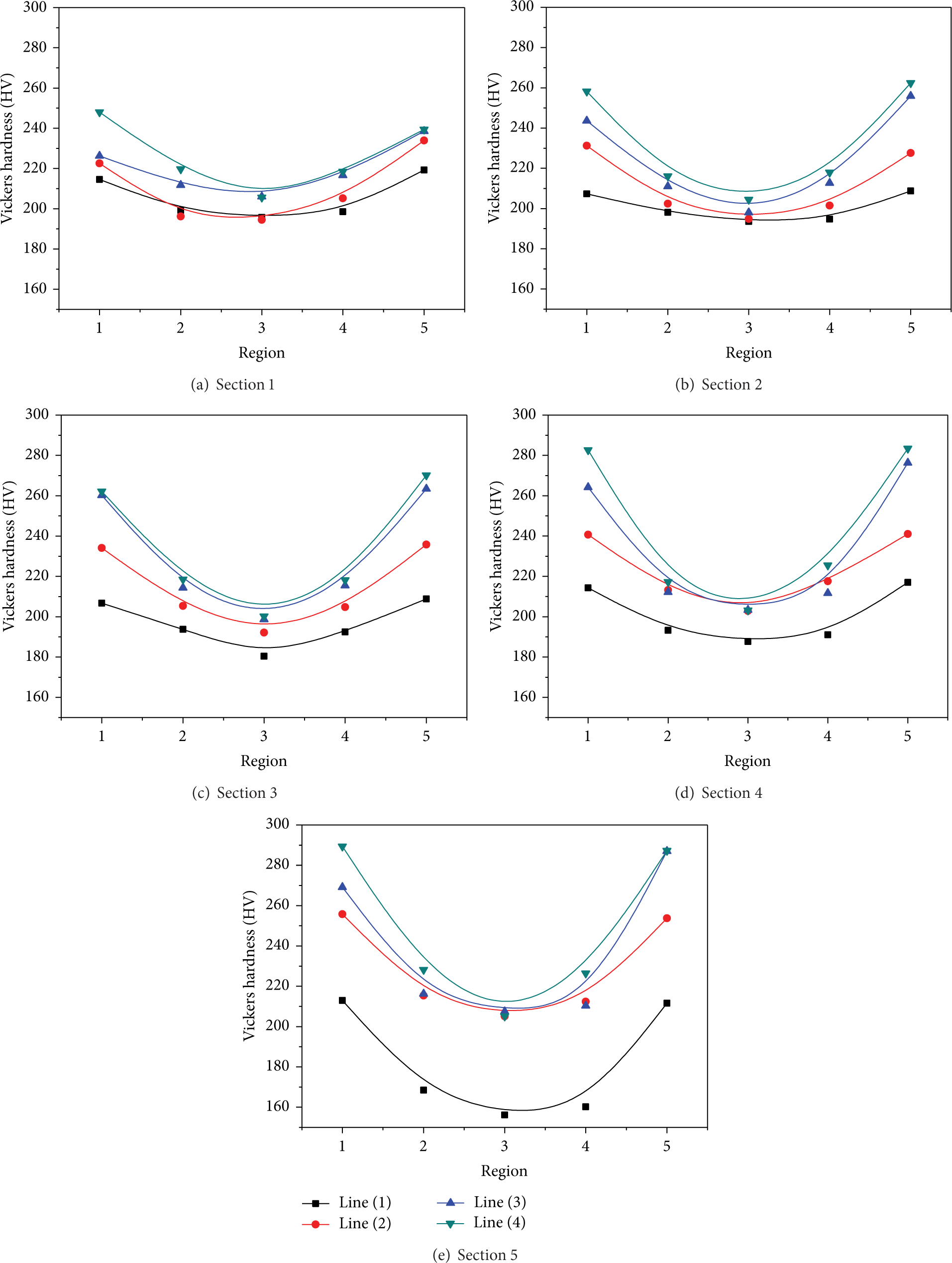
The distribution of the Vickers hardness in circumferential direction of transverse sections.
3.3.2. Distribution of the Vickers Hardness in the Radial Direction of Transverse Sections
The distribution of the Vickers hardness in the radial direction of transverse sections is shown in Figure 13. It can be seen from Figure 13(a) that in the surface of the gear tooth, the distribution of the Vickers hardness is inhomogeneous along the radial direction; that is, the Vickers hardness gradually increases from the addendum to dedendum of the gear tooth. This is because of the fact that, from the addendum to dedendum of the gear tooth, the plastic deformation in the surface of the gear tooth gradually increases, so that the degree of cold work hardening becomes more significant. In particular at the corner of the dedendum, the severe plastic deformation occurs in the dedendum surface, so the degree of cold work hardening is the most significant. However, in the middle of the tooth, the distribution of the Vickers hardness is homogeneous along the radial direction and the values of the Vickers hardness range from 180 HV to 200 HV, as shown in Figure 13(b).
The distribution of the Vickers hardness in the radial direction of each transverse section.
3.3.3. Distribution of the Vickers Hardness in the Axial Direction of the Gear Tooth
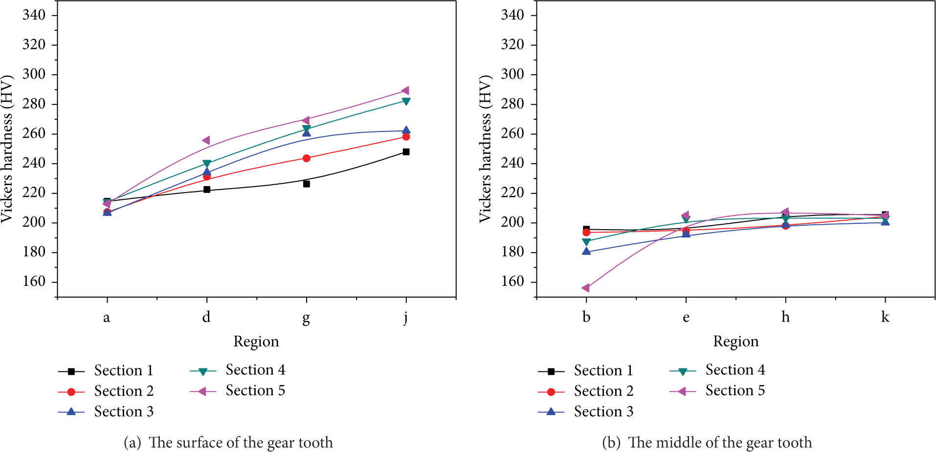
The distribution of the Vickers hardness in the axial direction of the gear tooth is also investigated in the present study, as shown in Figure 14. It can be seen from Figure 14 that the distribution of the Vickers hardness in the surface of the gear tooth is inhomogeneous in the axial direction; that is, the Vickers hardness gradually increases from the small-end to large-end (curves of region 1 and region 5 in Figure 14). This is because of the fact that the plastic deformation in the surface of the gear tooth gradually increases from the small-end to large-end, so that the degree of cold work hardening becomes more significant. However, the distribution of the Vickers hardness in the middle of the tooth is homogeneous in the axial direction (curves of region 3 in Figure 14). This is because of the fact that the distribution of the plastic deformation in the middle of the gear tooth is homogeneous from the small-end to large-end and thus the degree of cold work hardening is homogeneous.

The distribution of the Vickers hardness in axial direction of gear tooth.
4. Conclusions
In this paper, the inhomogeneous distribution of microstructure, the inhomogeneous deformation of the grain, and inhomogeneous distribution of the Vickers hardness in the gear tooth formed by cold rotary forging are investigated by using experimental and FE simulation method. The conclusions obtained are summarized as follows.
Processing by cold rotary forging, the grain deformation is inhomogeneous in the gear tooth because of the different plastic deformation. In the surface of the gear tooth, the grains are obviously stretched in various degrees along the metal flow direction. In the middle of the gear tooth, the grains are slightly stretched.
In the circumferential direction, because of the inhomogeneous plastic deformation, the aspect ratio distribution of the grain is inhomogeneous from the surface to the middle of the gear tooth and it exhibits an obvious U-shaped effect. The aspect ratio of the grain in the surface of the gear tooth is much larger while the aspect ratio of the grain in the middle of the gear tooth is much smaller. In addition, from the addendum to dedendum of the gear tooth, the aspect ratio distribution of the grain becomes more inhomogeneous in the circumferential direction, and from the small-end to large-end of the gear tooth, the aspect ratio distribution of the grain also becomes more inhomogeneous in the circumferential direction. The Vickers hardness has the similar distribution regulars with the aspect ratio of the grain in the circumferential direction. Furthermore, these regulars coincide with the distribution regulars of the effective strain in the FE simulation in the circumferential direction.
In the radial direction, the aspect ratio of the grain in the surface of the gear tooth gradually increases from the addendum to dedendum of the gear tooth, while the aspect ratio of the grain in the middle of the gear tooth is small and homogeneous from the addendum to dedendum of the gear tooth. The Vickers hardness has similar distribution regulars with the aspect ratio of the grain in the radial direction. Furthermore, these regulars coincide with the distribution regulars of the effective strain in the FE simulation in the radial direction.
In the axial direction, the aspect ratio of the grain in the surface of the gear tooth gradually increases from the small-end to large-end of the gear tooth, while the aspect ratio of the grain in the middle of the gear tooth is homogeneous from the small-end to large-end of the gear tooth. The Vickers hardness has similar distribution regulars with the aspect ratio of the grain in the axial direction. Furthermore, these regulars coincide with the distribution regulars of the effective strain in the FE simulation in the radial direction.
Conflict of Interests
The authors declare that there is no conflict of interests regarding the publication of this paper.
Footnotes
Acknowledgments
The authors would like to thank the Natural Science Foundation of China (no. 51105287), Key Research and Development Project of New Product and New Technology of Hubei Province (no. 2012BAA08003), Innovative Research Team Development Program of Ministry of Education of China (no. IRT13087), High-End Talent Leading Program of Hubei Province (no. 2012-86), and China Postdoctoral Science Foundation (no. 2013M531750) for the support given to this research.