
Abstract
This study investigates the design of a 7-DOF humanoid manipulator capable of playing table tennis with human-like stroke patterns. The manipulator system includes a redundant arm, real-time stereo vision system, and a distributed motion control system. First, the size, weight, workspace, and motion capability of the designed arm are similar to those of a human's arm. The forward and inverse kinematics, and the Jacobian matrix of the redundant manipulator are formulated. Next, a distributed motion control system is designed. The ball trajectory prediction method is proposed. Then, a human-inspired optimization method based on Jacobian pseudoinverse and the comfort of the arm posture for stroke pattern trajectory is proposed to achieve human-like stroke patterns and decrease the counterforce exerted on the manipulator. Finally, the validity of the proposed system and methods is demonstrated via human-like stroke pattern experiments.
1. Introduction
The challenging tasks of playing table tennis performed by robots have attracted many researchers [1–16]. They employed the table tennis robot as extensive research platform for artificial intelligence [3, 6], advanced control algorithms [1, 8], high speed machine vision and prediction [13], fast responses against unforeseen events [17], online trajectory generation within very limited time [2, 10, 15], target tracking and intercepting [6, 14], and so forth. These techniques are available widely in industries, medical services, and space explorations.
Andersson used a general industrial robot, PUMA 260, to achieve playing table tennis against humans with an expert controller. Modi et al. [11] built a table tennis robot using a five-DOF Mitsubishi industrial robotic arm, RV-2AJ. Matsushima et al. [1, 10] demonstrated a simple but effective table tennis robot mounted on the table. Acosta et al. [9] presented a low cost table tennis robot with two prismatic and three revolution joints and two paddles were mounted on the robot. Zhang et al. [13] built a five-DOF table tennis robot whose racket was restricted to the half-table. Recently, Lai and Tsay [12], Yu et al. [14, 16], and Zhang et al. [15] presented a seven-DOF robot to achieve playing table tennis dexterously. Mülling et al. [18] presented a biomimetic trajectory generation method to robot table tennis. Human table tennis players have multiple stroke patterns, such as push-block, chop, loop, drive, and smash. In previous works, basically only push-block stroke pattern was involved, which meant relatively low requirements to the manipulators: less degrees of freedom for the robotic player, smaller range of movement for the joints, lower linear and rotational velocities for the racket, and allowing larger mechanical mass and inertia. In this study, we take a biomimetic point of view to design an anthropomorphic manipulator involving mechanism and control methods based on the concept of the comfort of the arm posture in order to enable the manipulator to have the capability to achieve human-like stroke patterns.
The remainder of this paper is organized as follows. Section 2 presents the mechanical design of the manipulator. Section 3 introduces the kinematics analysis and workspace of the manipulator. The control system design and control methods are presented in Section 4. Section 5 gives experimental rally results of the manipulator against a human player. Conclusions are provided in Section 6.
2. Mechanical Design of the Manipulator
2.1. Design Principles
In order to imitate the strategy of the human players, the human's arm is taken as model of the manipulator. The movement patterns of the manipulator can cover the general human's stroke pattern: push-block, chop, loop, drive, and smash. The configuration of degrees of freedom of the manipulator mimics that of a human. The length of the upper arm and forearm of the manipulator is similar to an adult human. The weight and inertias of the manipulator are close to an adult human. The maximal linear velocity of the manipulator at its wrist can reach up to 3 m/s. The dexterous workspace is also similar to that of an adult human.
2.2. Mechanical Structure
According to the design principles, the manipulator has the mechanical structure as follows. The manipulator has seven DOFs configured in an anthropomorphic way: 3 DOFs in the shoulder, 1 DOF in the elbow, and 3 DOFs in the wrist. The axes of the three joints in the shoulder intersect at one point. The axes of the three joints in the wrist intersect at another point. The spherical wrist enables the manipulator to change the posture of the racket suddenly without utilizing the whole manipulator to imitate an abrupt wrist motion usually employed by human players.
Every joint in the arm is driven by a DC brushless motor from Maxon Company. The harmonic drive has the well-known advantages of no backlash and high reduction ratios in small space with low weight. Therefore, the harmonic drive is equipped with each joint as speed reducer. The compact design of harmonic drive component sets allows a space-saving integration directly into the joint units. Accordingly, the manipulator has both the light weight and high stiffness features which are important to the playing table tennis task. The designed manipulator is shown in Figure 1. The racket is mounted on the end of the wrist. The detailed specifications of the manipulator are in Table 1.
Specifications of the manipulator.


Structure of the manipulator and comparison with a human arm.
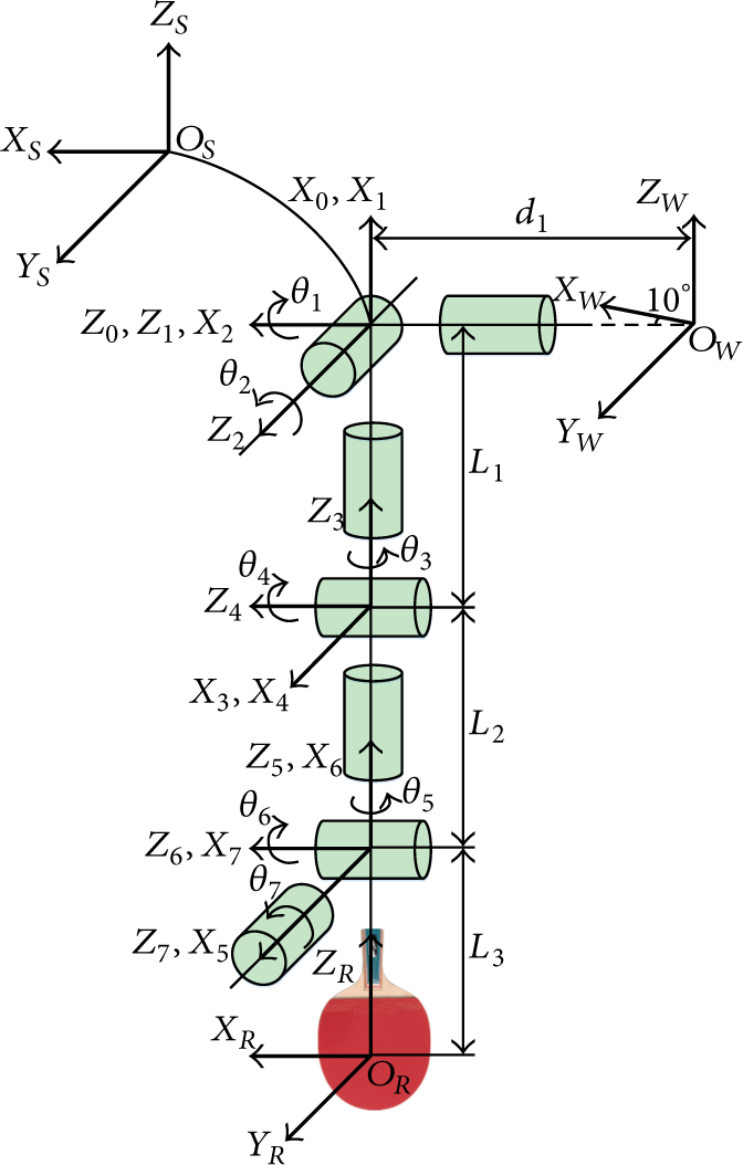
The arm is fixed on a frame (torso). To enlarge the valid workspace leftward for striking ball and to decrease the possibility of collision between the racket and the torso, there is an angle of 10 degrees indenting along the coronal plane, shown in Figure 2.

Assembly relationship of the arm and the torso.
3. Kinematics Analysis of the Redundancy Manipulator
3.1. Forward Kinematics
The kinematics model of the manipulator is shown in Figure 3. Ten coordinate frames are used to describe the position and orientation of the links and the manipulator. All the coordinate frames are built by the Denavit-Hartenberg method. The frames 0–7 correspond to the base and seven joints of the manipulator. The frames 0–2 are located in the shoulder; the frames 3–4 are in the elbow and the frames 5–7 are in the wrist. The origin of the shoulder frame O
S
X
S
Y
S
Z
S
is located on the point where the axes of the three joints in the shoulder intersect. The origin of the racket frame O
R
X
R
Y
R
Z
R
is located at the centre of the racket. To simplify the computation, all the following transformation of these coordinate frames is with respect to the shoulder frame O
S
X
S
Y
S
Z
S
. The homogeneous matrixes

where sθ i ≡sin(θ i ), cθ i ≡cos(θ i ), i = 1 − 7, and θ i (i = 1, 2 …, 7) are the joint angles.
Kinematics model of the manipulator.
Hence, the forward kinematics of the manipulator specified by the position and orientation of the racket (represented by the frame O R X R Y R Z R ) with respect to the shoulder frame O s X S Y S Z S is expressed by the matrix

The detailed result of
The Jacobian matrix of the manipulator, J, which denotes the transformation between the joint velocity vectors

where θ(t) is the joint angles vector of the manipulator,
3.2. Inverse Kinematics
In this section, we investigate the inverse kinematics issues to get the corresponding joint angles from the desired given position and orientation of the racket. One way to obtain θ(t) for given s(t) may be achieved by computing the joint velocity vector
One may determine

where J+(θ(t)) is the Moore-Penrose pseudoinverse of J(θ(t)), I is the identity matrix, λ is diagonal weighting matrix, and the vector ∇ϕ is gradient of a function of joint angles θ(t). The matrix [I − J+(θ(t))J(θ(t))] is a projector in the null space of J(θ(t)). The matrix λ is positive definite to maximize ϕ(θ(t)) and negative definite to minimize ϕ(θ(t)). And
Since this manipulator has an additionally redundant joint, we may exploit this feature to optimize the motion of the manipulator not causing motion of the end-effector in accordance with (4). We employ a concept based on the comfort of posture for the human arm presented by Cruse et al. [21] and Mülling et al. [18] to build a cost function for optimization as follows:

where θ iM and θ im denote the maximum and minimum joint limits and θ ir denotes the angle value of each joint at ready position and posture. We use this inverse kinematics approach to achieve human-like stroke patterns and decrease the counterforce exerting on the manipulator.
3.3. Workspace Analysis
In this section, the workspace of the manipulator is analysed. As previously described, there is an angle offset of 10 degrees between the coronal plane and the z0-axis. The workspaces of the manipulator computed by the matrix

Workspace of the manipulator.
4. Control System Design
4.1. Control System Structure
The control system of the manipulator is constructed as distributed control architecture (Figure 5). There are two personal computers employed in the system. One PC is used for vision processing to get the ball trajectory with Windows XP operating system, and the other PC serves as main motion controller for motion planning and servo control with RT_Linux operating system. The two PCs exchange data through TCP/IP protocol. A controlled area network (CAN) bus is used to support communication between the main motion control system and the distributed joint controllers via CANopen protocol at the bit rate of 1 Mbps. All joints are actuated by DC brushless motors. The main motion control computer sends the joint reference trajectories to each distributed motor controller to drive the racket to intercept the incoming ball and acquires the joint actual position feedback with a period of 3 ms.
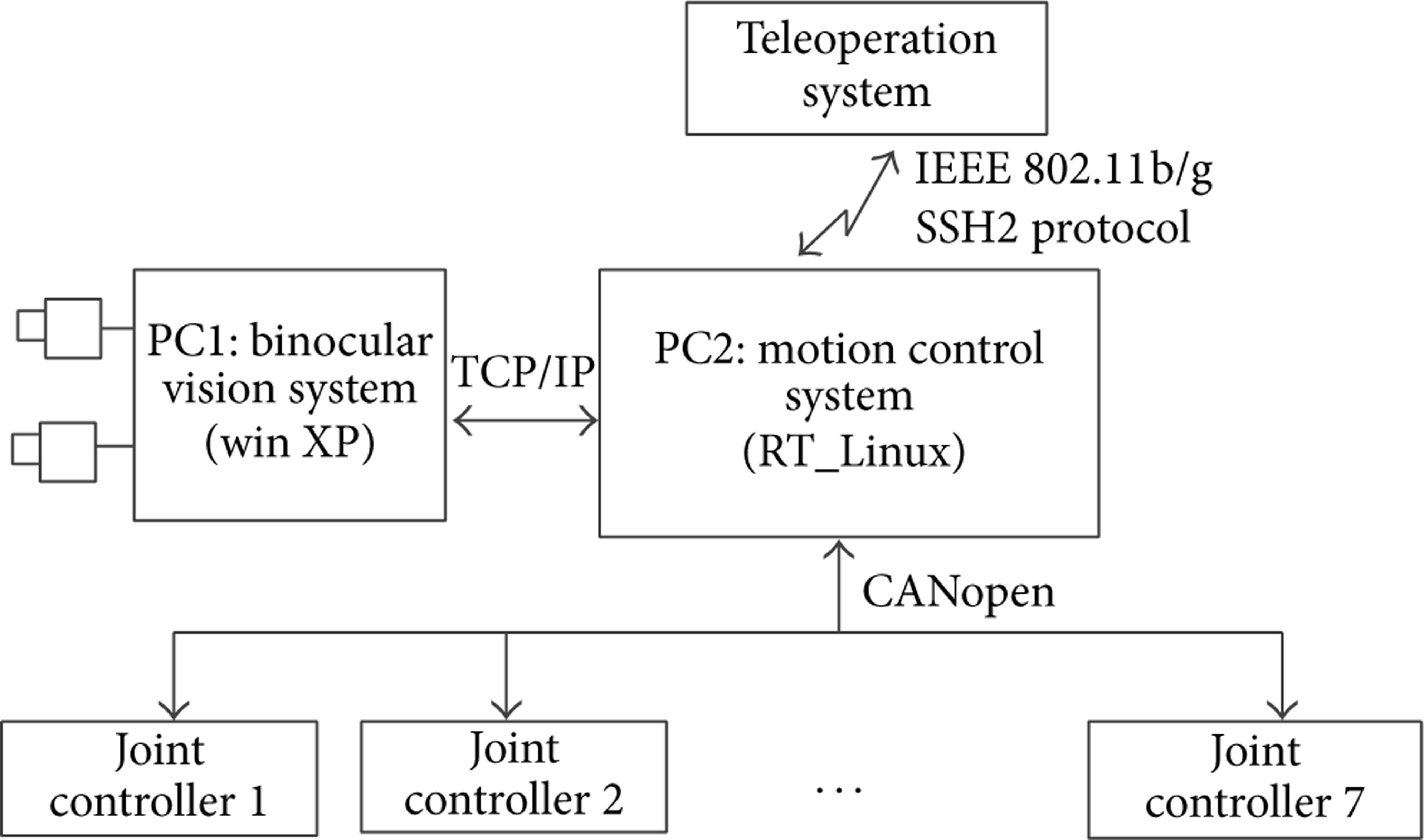
Architecture of the distributed control system.
4.2. Binocular Vision System
Two colorful digital cameras with 640 × 480 resolutions up to 200 fps and IEEE1394 bus are employed to build binocular vision system for ball identification.
The ball identification algorithm processes color images in HSV (hue, saturation, and value) color space. Firstly, the two cameras grab images simultaneously by external synchronous triggering at 125 fps. Next, the images are enhanced in RGB color space, converted from RGB to HSV space, and segmented in HSV using threshold. In order to improve the accuracy of identification, each image is segmented into several domains and consequently the intersection of these segmentation domains is attained. Then, according to the shape feature of the intersection domains, the area of interest (AOI) can be selected out. For the sake of improving the accuracy of the center coordinates of the ball, it is necessary to process the area of the ball further in order to obtain the subpixel edge of the ball. The edge of the ball is fitted to an ellipse and the accurate center coordinates of the ball can be gained. Figure 6 shows the flow chart of the algorithm of the ball identification. As long as the coordinate of the area center is acquired in each camera image, the 3D Cartesian coordinates (x,y,z) of the ball in camera system can be easily synthesized. The vision system outputs the ball trajectory (x,y,z,t), that is, the ball coordinate sequences, with respect to time. The update rate of the coordinate is 125 Hz. The dynamic accuracy of the ball coordinates by root mean square is less than 5 mm.

Ball identification algorithm.
4.3. Ball Trajectory Prediction
Generally, an entire process of playing table tennis by a manipulator includes the following.
Human (or machine) serves a ball.
The vision system of the manipulator grabs the ball images and predicts the subsequent ball trajectory using a series of ball positions and velocities with aerodynamics and bounce model, plans the stroke motion, and then drives the racket.
The ball bounces on/off the table at the manipulator's side.
The racket strikes the incoming ball at an appropriate stroke plane.
The ball flies and bounces on/off the table at the opponent's side. This concludes one rally cycle.
In this study, we assume that the ball has low spin so that we can ignore the Magnus force impacting the flying ball. Therefore, we used a simplified ball flying model from [5] as follows:

where
We adopt a simplified linear bounce model against table as follows:

where
Generally, an entire prediction period of the ball includes flying phrase before bounce, bounce phrase against the table, and flying phrase after bounce. Thus, the position of the ball can be attained with flying and bounce model by numerical iteration computation.
4.4. Racket Trajectory Planning for Stroke Patterns
As for a given ball trajectory, T(x,y,z,t), if the value of x is fixed, the values of y, z, t and the corresponding velocity of the ball can be uniquely determined. So, a ball gets through a prescribed plane (x equals a prescribed value) and then an intersection point (called stroke point here) between the trajectory and the prescribed plane will be gained. The mission of the racket trajectory planning for stroke patterns is to generate an appropriate trajectory for the racket to arrive at stroke point simultaneously with a specific velocity vector to intercept the ball back to the opponent player. This prescribed plane is named as stroke plane. The generation procedure of the racket trajectory is shown in Figure 7. First, the required posture (α s ,β s ,γ s ), velocity (v xs ,v ys ,v zs ), and location (x s ,y s ,z s ) of the racket at stroke plane x = x s and stroke time t = T s are determined by ball aerodynamics and bounce model, according to the location and velocity of the incoming ball at stroke plane, as well as the desired landing point on the opponent's side after the stroke.
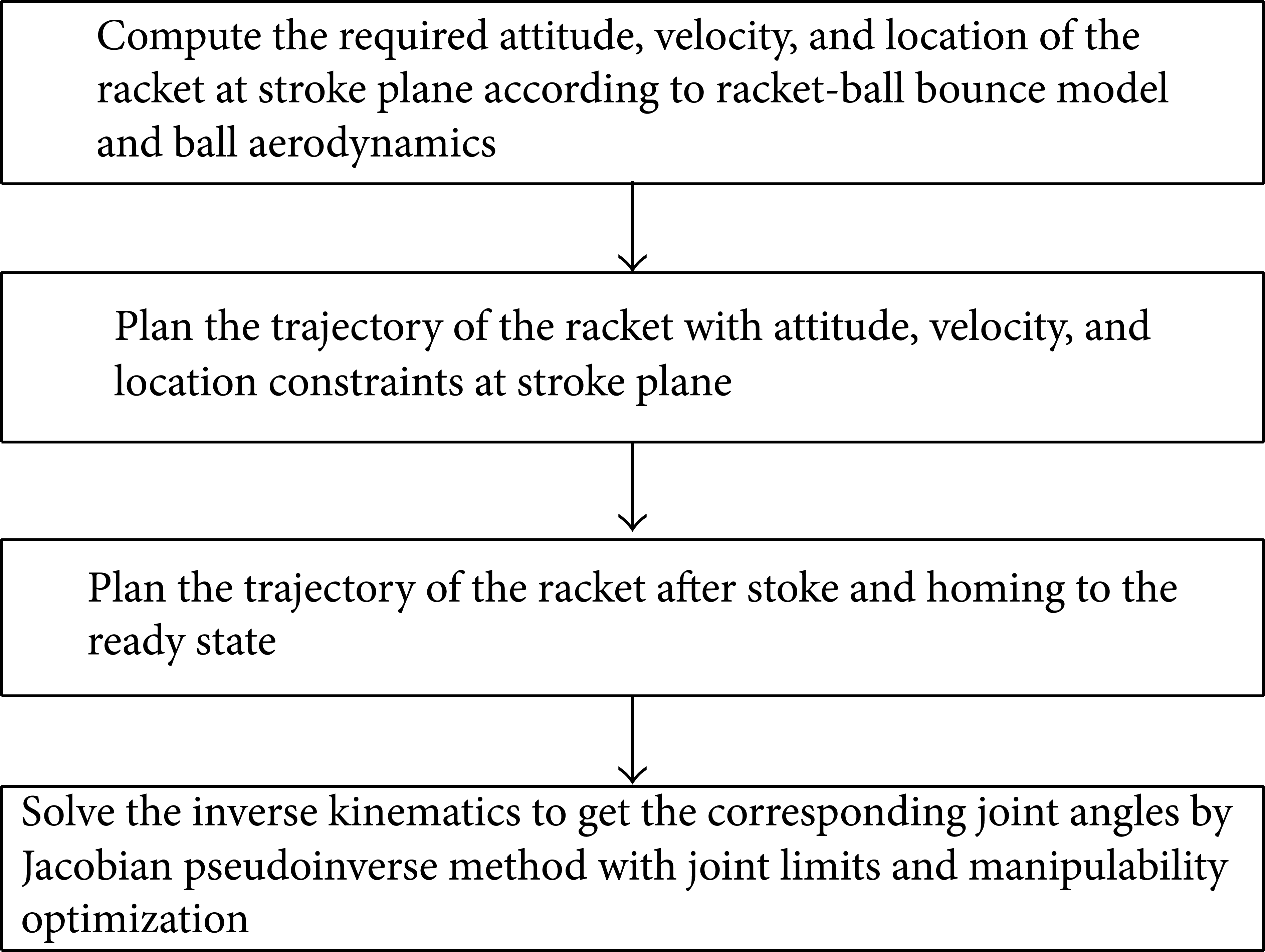
Planning algorithm for racket trajectory.
To calculate
Boundary conditions for generating stroke patterns.
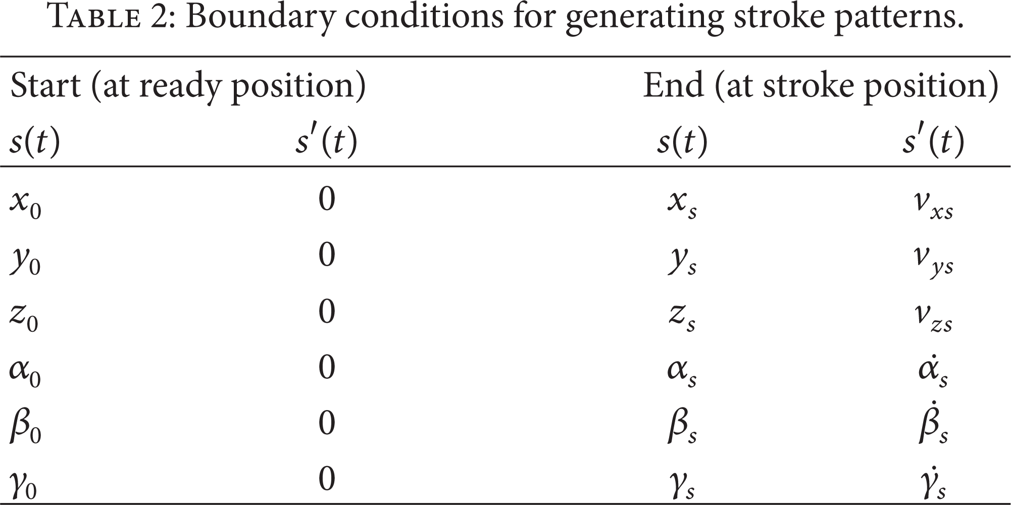
It should be pointed out that the ZYZ Euler angles ∅(α,β,γ) are exploited to represent the attitude angles here. So, to calculate rotation angular velocity ω (ω
x
,ω
y
,ω
z
) from
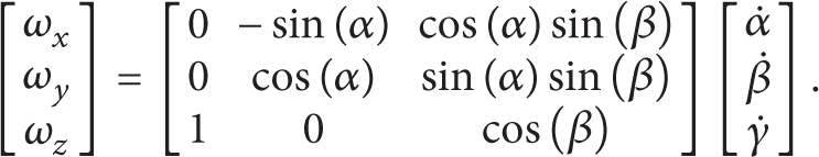
To generate various stroke patterns analogous to human players, such as push-block, chop, loop, and smash, we can accomplish these easily through designating various linear and angular velocity and location of the racket at the stroke plane.
5. Experimental Results
In order to validate the effectiveness of the proposed methods and the designed manipulator, we performed a series of experiments with various stroke patterns. A standard table (size: 2.74 m × 1.525 m × 0.76 m) and standard ball (diameter: 40 mm, weight: 2.7 g) were used. A world reference frame for the robotic system was defined as follows: the origin was mounted at the center of the table surface; the positive x-axis pointed to the manipulator along the midline on the table; the positive y-axis pointed along the width direction of the table to the right side of the manipulator; the positive z-axis was upward and determined with right-hand rule. The stroke plane was assumed at x = 1.250 m. We assumed the robot situated at the location where the coordinates of the intersection point of the three joints in shoulder were 1.5 m, 0.1 m, and 0.63 m in the world frame and the axis of the pitch joint in shoulder was in parallel to the positive y-axis of the world frame.
To illustrate the experimental results, a loop stroke pattern was provided here. In order to intercept a specific incoming ball to backtrack to a desired area, the position and Euler angle of the racket (x,y,z,α,β,γ) at the stroke plane should be −0.0265 m, 0.5239 m, and −0.4420 m and 0.0149 rad, 2.1323 rad, and −3.0552 rad. The linear and angular velocities of the racket at the stroke plane should be 0.2149 m/s, 0.4015 m/s, and −0.1514 m/s and −3.2984 rad/s, −0.5044 rads, and −3.5253 rad/s. The strike time should be 0.364s. Equation (4) was employed to compute the joint trajectory. To compensate the long-term drift using (4), a closed-loop scheme presented in [22] was employed. Moreover, to decrease the tracking error of the manipulator due to inertia and the power constraints of the actuators to achieve the interception, the reference trajectory was executed ahead of the desired time by three servo cycles. Figure 8 shows the racket trajectory and the corresponding joint trajectories from the ready state to the stroke plane. The computed position and Euler angle of the racket at the stroke plane (x,y,z,α,β,γ) were −0.0264 m, 0.5239 m, and −0.4418 m and 0.0132 rad, 2.1327 rad, and −3.0573 rad. The computed linear velocity of the racket at the stroke plane was 0.2131 m/s, 0.3989 m/s, and −0.1480 m/s. As is shown from the results, the tracking errors are very small. Figure 9 shows snapshots from a video of human-manipulator rally.

Racket trajectories in world reference frame and joint trajectories for stroke.

Snapshots from a video of table tennis playing.
6. Conclusion
In this study, a seven-DOF redundant humanoid manipulator for playing table tennis with stroke patterns analogous to human players was designed. The main contributions of this study are as follows.
From the biomimetic point of view, a redundant arm was designed with physical attributes and motion capability similar to those of a human's arm.
A human-inspired optimization method based on the concept of the comfort of posture for stroke pattern trajectory is proposed. Based on the Jacobian pseudoinverse, it can easily achieve human-like stroke patterns and decreases the counterforce exerted on the manipulator.
The effectiveness of the proposed system and methods is validated through stroke pattern experiments.
Footnotes
Appendix
Consider the following
where
where
Conflict of Interests
The authors declare that there is no conflict of interests regarding the publication of this paper.
Acknowledgments
This work was supported by the National Natural Science Foundation of China under Grants 61320106012, 61375103, 61273348, and 61175077 and “111 Project” under Grant B08043.