
Abstract
Polishing process is one of the manufacturing issues that are essential in the production flow, but it generates the major amount of defects on parts. Finishing tasks in which polishing is included are performed in the final steps of the manufacturing sequence. Any defect in these steps impliesrejection of the part, generating a big amount of scrap and generating a huge amount of energy consumption, emission, and time to manufacture and replace the rejected part. Traditionally polishing process has not evolved during the last 30 years, while other manufacturing processes have been automated and technologically improved. Finishing processes (grinding and polishing), are still manually performed, especially in freeform surface parts, but to be sustainable some development and automation have to be introduced. This research proposes a novel polishing system based on robotics and artificial vision. The application of this novel system has allowed reducing the failed parts due to finishing process down to zero percent from 28% of rejected parts with manual polishing process. The reduction in process time consumption, and amount of scrapped parts, has reduced the energy consumption up to 30% in finishing process and 20% in whole manufacturing process for an injection moulded aluminium part for automotive industry with high production volumes.
1. Introduction
This research shows a Nobel Intelligent System to finish parts and tools with grinding and polishing technologies and especially artificial vision development. The main objective is to develop an environmentally conscious automated system to reduce scrap and defect parts in an industrial process. Polishing process is one of the manufacturing issues that are essential in the production flow [1]. Traditional hand-made processes, as polishing, are made without control system and imply a huge amount of energy and raw material consumption to repose the big number of wrong parts that are generated [2]. New developments and automation have to be introduced in finishing processes as grinding and polishing, especially in freeform surface parts, in order to be sustainable [3].
This new robotic process will be applicable to different industrial sectors in metal working industry, and specially in aeronautical and automotive sectors, thorough the improvement of the automation of the manufacturing task that are nowadays used in these industries. Our research applies a new tool or concept based on robotics and artificial vision which will be useful for both metal and composite parts. This paper shows the results in the case of metal parts as the scope of the research.
Finishing process is the last manufacturing task in the production line. First steps are the production of metal parts by foundry or injection process and then the process finishes by manual polishing step. Polishing process reveals a lot of defects carried from the previous task [4, 5] that makes parts to be rejected. The usual procedure is to reject parts when defects are shown in a final inspection. This means that a big amount of energy has to be used to produce a new part to replace the rejected part. Moreover, the rejected part has to be molten to generate new raw material to be reused, which implies extra energy expenditure.
The concept of the development of the system is based on an in-line inspection of the finished surfaces of the part, to check if it fits the requirements. If this validation results negative finishing process will be remade, but only in the defective areas, avoiding the rejection of the part or even the full finishing process execution.
Finishing process development is inherited from previous research [6, 7]. The previous studies demonstrated the shape of the footprint of a tool that combined a rotational and translational movement to polish flat or big curved freeform surfaces. The tool was assembled to a robot and its position was controlled. The features of the multilayered tool with a foamed urethane core allow contact pressure to be near constant. Under these conditions, polishing these kinds of surfaces is feasible.
Artificial vision inspection system and the integration with CAD/CAM [8] and robotic system are the core newness of the investigation.
The procedure begins with the human inspection and further tracing of coloured marks on the finished part underlining the defective areas. System is able to automatically detect them and generate the actuation operation sequence to define and execute the necessary actions to reach the grinding and polishing task accordingly to the required quality parameters. System makes an image capture of the part in the polishing cell, analyzes and processes the acquired data related to the marked contours, and shows the robot the zones where a further process treatment is required.
Using artificial intelligence it detects marked contours position and shape with accuracy less than ±2 mm. This accuracy is enough to accomplish the project technical specifications.
As direct consequence of the project energy use saving is expected [9, 10]. The competitiveness of the companies using the new system will increase, by means of the integration of new industrial development that will reinforce the modernization, automation, and optimisation in the finishing process applied to parts and tools.
2. Materials and Methods
Complete system is divided into differenced subsystems: one related to artificial intelligence and another related to managing robotic issues. Final system uses both of the subsystems as a whole.
Artificial vision system uses an AVT vision camera and mathematical software to generate the artificial vision code, while robotic system is mainly composed by a Kuka robot and different polishing tools that are the result of previous research [6, 7].
The workpiece consists in an aluminium injection moulded part for automotive industry. The general dimensions are 500 × 400 × 30 mm. All visible surfaces must be polished after injection processing to soften the surface and suppress any additional surface treatment. As the polishing tool cannot polish groove shapes, only flat or large curvature radius freeform surfaces are treated. In the particular case of this workpiece, there are not groove shapes in the part to be polished. It is an automotive part where only the seen surfaces need to be polished and all are nearly flat. Only some holes are present in these surfaces. The groove shape surfaces around the polishing area do not belong to the part, but they are the special tooling to fit the part to the machine. So, under these conditions, the polishing tool can develop its polishing task without restrictions.
Figure 1 compares the actual system used in general industry with the new process flow proposed in the research (Figure 2). After workpiece is assembled in the working area the robot executes the polishing cycle. Afterwards, if the inspection results right the part is finished. If not, the failed areas or the defects are marked inside coloured contours drawn manually after inspection. An artificial vision system detects these contours and automatically regenerates the new CAM paths. Defective areas are polished again with the new CAM by the robot. The result of the inspection check validates the part or not and additional loops of these tasks are done until the part is finished.

Current polishing process workflow.
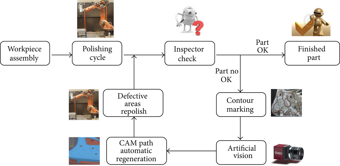
Proposed polishing process workflow.
2.1. Artificial Vision Components
Image acquisition is performed by a colour progressive CCD camera (Figure 3), model Guppy F080C (Allied Vision Technologies, AVT). This is camera shows the compact size required for the application, and a Firewire IEEE 1394a interface, with a transfer data speed of 400 Mb/s, that allows the interconnection of the camera with a PC with high speed data transfer performance.

Guppy F080C camera and sensor response curves.
MATLAB (The MathWorks) is the mathematical software tool that shows a development framework integrated with a powerful programming language suitable to process digital images. Toolbox utilities allow programmers to develop specific user algorithms. Moreover hardware integration can be included, so it is possible to manage and automate AVT camera shot. Camera maximum resolution is 1032 × 778 pixel and is powered with a Sony ICX204 CCD sensor. Its reduced dimensions and weight (50 grs) make it possible to attach it to the robot avoiding collisions and interferences with the robot poses when polishing and part data acquisition is performed.
2.2. Polishing Process and Robotic Components
Polishing cell is based on an industrial robot Kuka KRC60HA. This is an industrial manipulator that has been adapted to perform polishing task as an automated way. Setting up polishing operations is supported by several probes: one to align and centre the workpiece and another to setup tool length and diameter. Tools shown in Figure 4 and finishing methodology have been developed in previous research [6, 7]. The polishing tool has a multilayer design. Between the abrasive and the support, there is a urethane foam layer of 5 mm thickness. It allows a contact pressure near constant when a compression between 10 and 50% of the foam occurs. Roughness profiles were measured with a confocal system for flat or big curved surfaces to ensure the feasibility of polishing with this kind of tool. Under these conditions, uniform polishing and surface quality can be achieved for flat surfaces or big curved surfaces. Minimum curvature radius can be calculated as a first approximation with the maximum compression of the foam (50% of the thickness) and the tool diameter. The combination of the translational and rotational movement of the tool influences the uniformity of the polished surface. The study and experimentation demonstrated the relationship between the combined movement and the shape of the roughness distribution. The tool footprint approximates to a “W” shape profile on the polished surface. It is mainly influenced by the combined movement and the increase of circumference speed with the radius of the tool [6]. The appropriate combination of the tool footprint with the number of tool passes and overlap between passes allow us to overcome the problems of nonuniform surface quality and uniformity. The process developed and described in this paper has only position control. The multilayer tool with urethane foam is always compressed between 10 and 50% of its thickness to ensure that the contact pressure is as much uniform as possible. So pressure control is achieved with the mechanical and geometric features of the tool and the position control.

Finishing robotic cell and grinding and polishing tool.
Robot controller is connected to an external PC where CAM software is running. In this case CAM software is used to make an off-line programming of the robot trajectories, movements, and poses to move the tool polishing the part. PowerMill (Delcam) is the software that will be used.
CAM software is first used to program the whole movements to make the polishing process of the workpiece. Moreover, this movement sequence will be adapted to rework the part if any surface defect is observed after the finishing task.
2.3. Methodology
Figure 2 shows a global view of the proposed methodology for the environmental conscious automated polishing system. The proposed procedure is divided into four main points.
First Step Automated Polishing Process. This is the first task in the robotic polishing cell. Workpiece is assembled in the tooling, and then when cycle starts, robot performs the polishing trajectories programmed using parameters from the technology data base. Once finished the human inspector checks the part and underlines the areas where polishing defects or previous traces are detected.
Camera Data Acquisition and Digital Image Processing (Guppy Camera, DCAM, MatLab). Robot moves to a home position to start the image capture. Then shot is done using parameters configured in MatLab software. Then data from the image acquired is processed to obtain and compute the contours. Finally contours are translated in an IGES format exchange file.
CAM Trajectories Regeneration (CAM). Information from IGES file is read, and CAM path [11, 12] is modified to be applied only in the defective areas. Connecting movements are generated and the whole robot movement sequence is checked to avoid collisions and to verify that no singularities exist. Information is post processed to generate a robot language based file that is transferred to the robot control to be executed.
Finished Part Disassembly. Points (2) and (3) will be sequentially repeated until human inspector decides that quality achieved fits the surface requirements for the finished parts. Once the part is finished it is removed from the tool, and cycle starts again.
Figure 5 shows the workflow methodology for artificial vision and automated CAM path regeneration that involves the core innovations of the research.
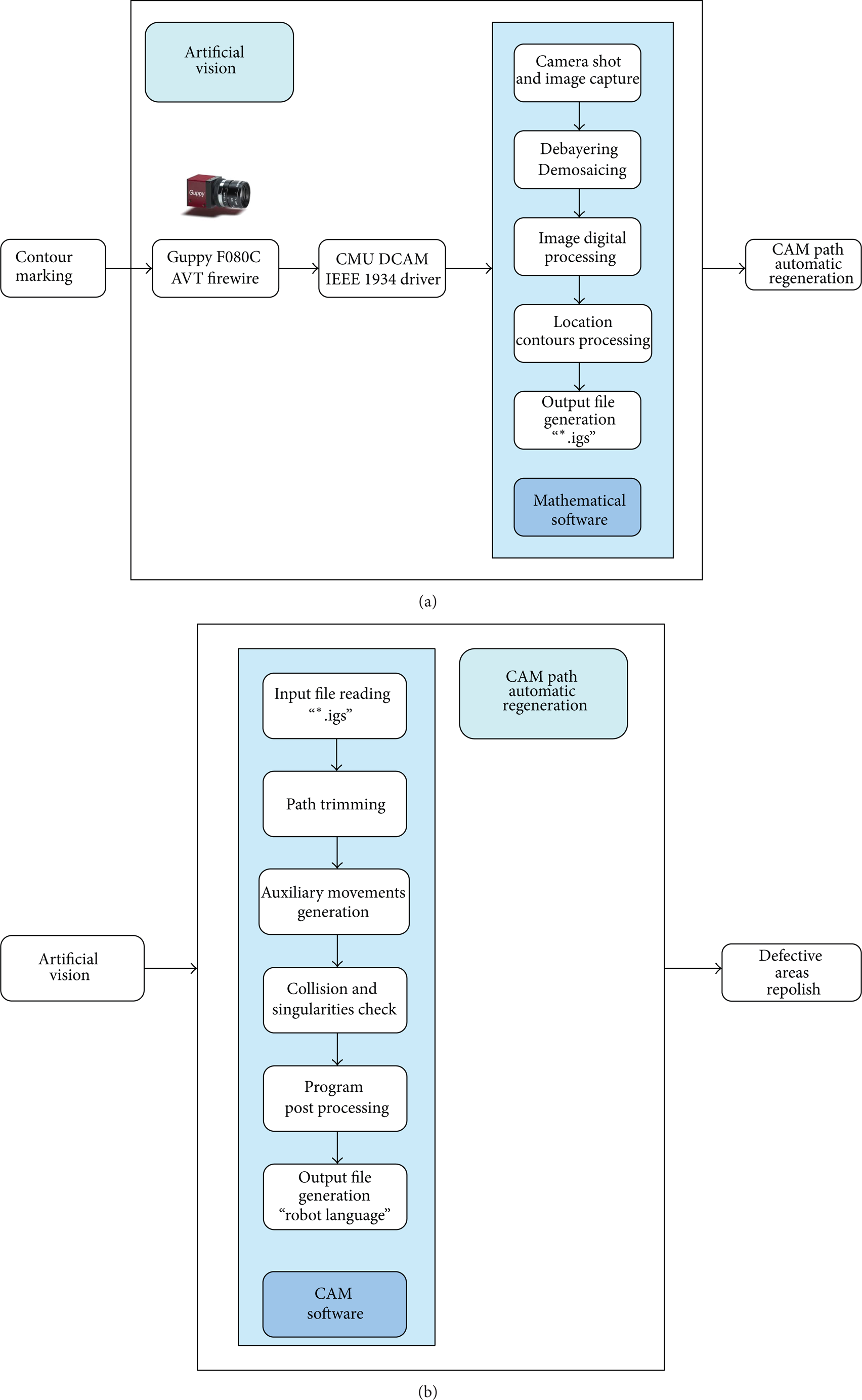
Artificial vision and CAM path automatic regeneration procedure.
2.3.1. Artificial Vision Methodology
Data Acquisition Process. Communication between Guppy camera and Mathematical software is designed through a CMU 1394 DCam driver, developed by Mellon University that is available in the Image Acquisition Toolkit, and enables the integration of the Firewire cameras permitting the camera shot directly from the software.
Before the shot is done it is possible to configure the parameters to align the Bayern sensor, the number of frames per shot, expiring time, and so forth. Image capture is automated, done by MatLab, such a way that when system starts it shows a preview of the part picture and then captures the image to be processed.
Images are captured in Y8_1024 × 768 format. White autobalance is activated and maximum opening size is used to permit a better answer for illumination changes or disturbs.
Figure 6 shows the camera assembled on the robot spindle. Camera is located pointing in perpendicular direction to the part main surface. Robot home position for the shot is constant, the same way the part is fixed, in order to maintain the same cartesian frame.

Camera mounted in the robot spindle.
Colour Image Obtaining. Debayering. Camera captures also colour related image information, but these data are “encoded.” Direct view in MatLab shows a grey scale image. The reason is that, during the capture process, if colour information is required, it is necessary to do interpolation using the Bayer filter, that weights up RGB [13] levels for each pixel.
In this case, camera sensor corresponds to RGGB Bayer filter; then, it is necessary to perform debayering process in MatLab, making the captured image interpolation, using RGGB filter, to obtain a digital image in RGB colour workspace. Filtering process is done as it is shown in Figure 7, and following equations are used to define RGB colour values for each of the tree final pixels:

Debayering process is required because sensor is compounded of a pixel matrix, where every pixel has a Bayer filter, and analyses light level for one of the tree primary colours (red, green, and blue) [14], such a way every pixel retains the information of light level and not colour data. The transformation of this information to the colour workspace is done through the interpolation based on the Bayer filter.
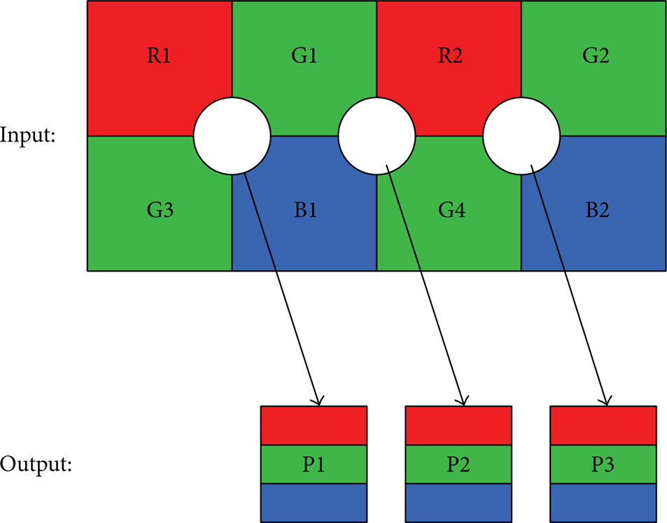
Bayer filter and interpolation.
Image Digital Processing. Once colour related information acquisition in MatLab, digital image processing technologies will allow first detecting red pixel and afterwards computing the information related to the different contours generated.
The system developed contours drawn in the 3 primary colours could be detected in separate files. The use of the red colour is because red is the most different colour from the raw material ones. Although trials with blue and green have been successfully done, some blue or green reflexes could appear in the metallic workpiece in an industrial environment.
In artificial vision systems lightning conditions play an important role and facilitate finding pattern inside the captured images. System will work in a robotic system, so light sources that could difficult robot movements and poses must be avoided. That implies the use of robust image processing algorithms and solid capture parameters stable enough in front of illumination variations, to obtain a satisfactory performance of the system.
After this process a digital image is obtained in the colour workspace RGB (red, green, and blue). MatLab internally represents colour digital images as a matrix m × n × 3 (Figure 8).

RGB image matrix form.
MatLab permits the access to the information of the tridimensional matrix that contains the data associated with colour intensity in every pixel. A statistical analysis is then required to identify red pixels in the contours. A simple methodology is to set a threshold and select the pixels with values over this level, but the problem is that there are several colours that in fact present high red component values. It is necessary to make a mathematical analysis in detail to select only actual red pixels in the contours.
This detection is done using different digital processing filters as median filter in two dimensions. It eliminates impulsive noise (“salt and pepper” in digital image processing terminology). Finally potential red pixels that appear isolated and that indeed do not belong to any contour are eliminated.
Red Contours Detection. After identifying red pixel within the image, it is required to analyze which red pixels that belong to the same contour and compute the amount of existing contours.
In several occasions red pixels appear with some disturbs due to the lightning, shadows, part borders, reflex, and so forth. This defect implies that these red pixels are not assigned to the correct contour and generates contours with discontinuities, as the one shown in Figure 9(a). Discontinuities problem must be solved in order to enable the complete contour detection. For this reason dilatation function and the suitable morphological structures are used. When the case in Figure 9(a) is analyzed and the final dilatation process passed complete closes contour the case in Figure 9(b) is obtained.

(a) Detected pixels. (b) complete contour generated.
Using this technique most contours are detected as complete ones, without discontinuities. In some cases that still some discontinuity remains, they are small enough that the algorithm developed is able to correctly compute the contour.
Contour computing algorithm output data consists in information about the number of contours and the position of the points that defines the external line of them. Figure 10 shows an example of the found contours in a sample image and the computation—in red—for the points in the external line of the contours. Cartesian coordinate position information of the red points and the amount of contours is compiled in the output file, that is encoded with the extension IGES.
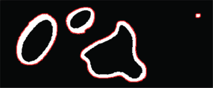
Contour points computation.
Detailed analysis of Figure 9 reveals a white pixel area detected as contour. In order to avoid noise in the image this area is detected as a contour. A further filter is programmed to eliminate detected contours that correspond with noise effects. This process is based on dimensions and position parameters, evolving to nonvalid contours. These are not included in the output file.
Cartesian Coordinate System and Calibration. During MatLab processing, coordinates depend on the pixels of the captured image, whose size is 768 × 1024. Point coordinates are determined in function of the position of the pixels in the image. Robotic system presents different coordinate system frame; moreover, it works with different units; then, it is necessary to make the right conversion between MatLab pixel position and the positions that are used in the robotic system. Figure 11 represents the coordinate change frame transformation in both systems: origin point translation, offset application, and the correct calibration in millimetre of the pixelated image.
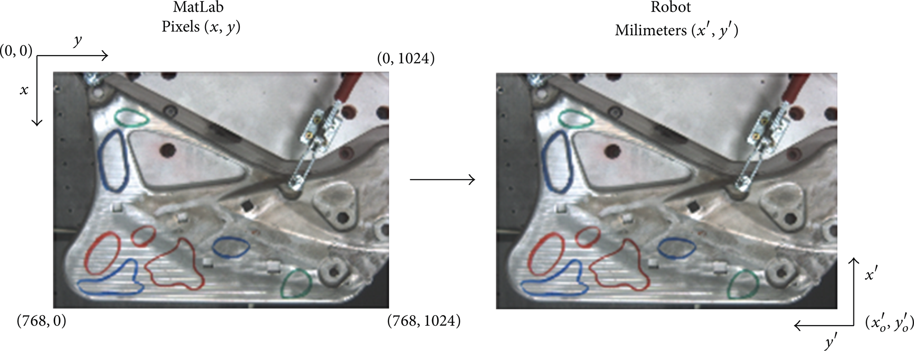
Relationship between MatLab and robotic system coordinate system.
After the correct conversion of the contour point position data, this information is written in the output file.
Example of the Processing Procedure. Figure 12 shows the main steps of the workflow to contour detection using image digital processing.
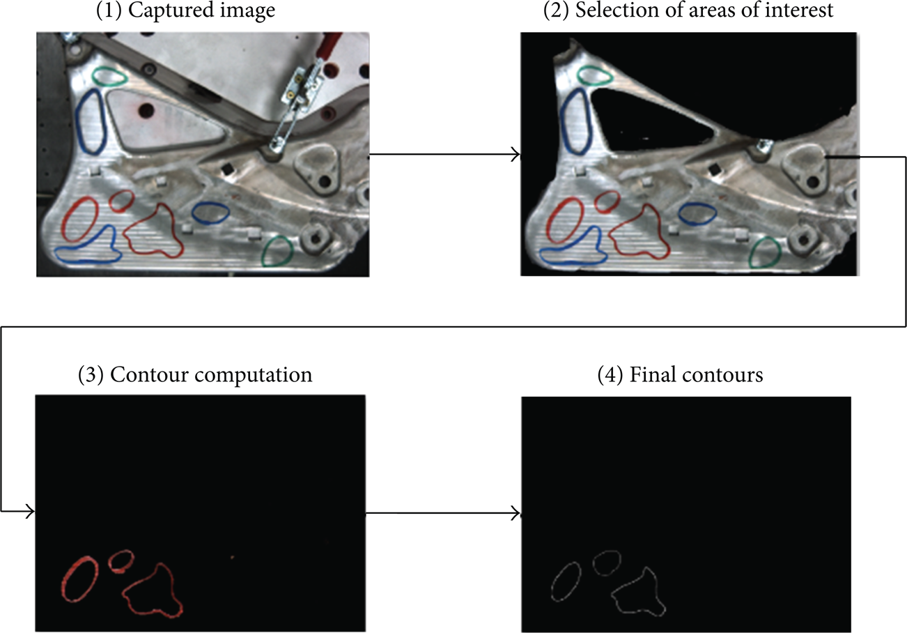
Image digital processing main steps.
2.3.2. CAM Regeneration
CAM Generic Polishing Path Generation. CAM software is used to generate the trajectory that polishing tool has to do in order to process the workpiece (Figure 13). Based on previous research [6] this programming has been done in Power-Mill environment. As input data, 3D geometry of the part is required as well as information about tools and technological parameters of the process.

CAM polishing path.
Once the programming is done and optimized, an output file is generated. CAM system provides information about the points, in Cartesian coordinates, that the tool has to follow, as a path in order to perform the task. Information provided contains also data about tool orientation. This information has to be translated to robot language, by the use of postprocessor software, and then sent to the robot in order to do the actual polishing in the robotic cell (Figure 14).

Robotic polishing and final part obtained.
CAM Regeneration for Specific Area Reprocess. The novel development in this case is based on the automated regeneration of the CAM paths in order to apply polishing strategies only in the areas of the part where defects were detected. For this point, the input data is the IGES file coming from the Artificial Vision System. IGES format is a neutral 3D CAD data transfer standard that is used to transmit 3D information between different CAD systems packages. In this case an IGES generator has been developed in MatLab, in order to send to the CAM system the cartesian 3D position of the points in the red contours marked during human inspection of basic polishing. To simplify the transfer and to speed up the application, reducing computation time, information for each contour is based on point information, and data containing the order in which these points have to been joined in order to build up the contours based in lines.
Software developed launches CAM software, opens the file where basic polishing strategy is defined, and runs a macrosystem. This macrosystem imports IGES data and cuts the original paths saving the parts of the trajectory that are inside the contours and erases the rest. Moreover, it generates a path that follows the contour defined and creates the movements to connect all the path parts. Once the process is done, it generates the movement code in robot language using postprocessor.
Figure 15 shows the image captured by the camera. It shows a part polished with the basic polishing process. Red contour marked by the quality inspector is also present. As analysis result, it shows a preview of the contour detected by MatLab. IGES file generated is brought in CAM system and after executing the macro the path is cut through the contour.

Captured image from the developed software.
Detected contour is also viewed in the CAM system. It is represented as a purple curve in Figure 16(a). Afterwards the two different path trajectories are generated. The first one is the trimmed version of the whole polishing trajectory, limited to the inner area of the contour. The second one, represented in Figure 16(a) as a green curve, is a polishing trajectory following only the curve of the contour, with an offset equal to half the tool diameter.
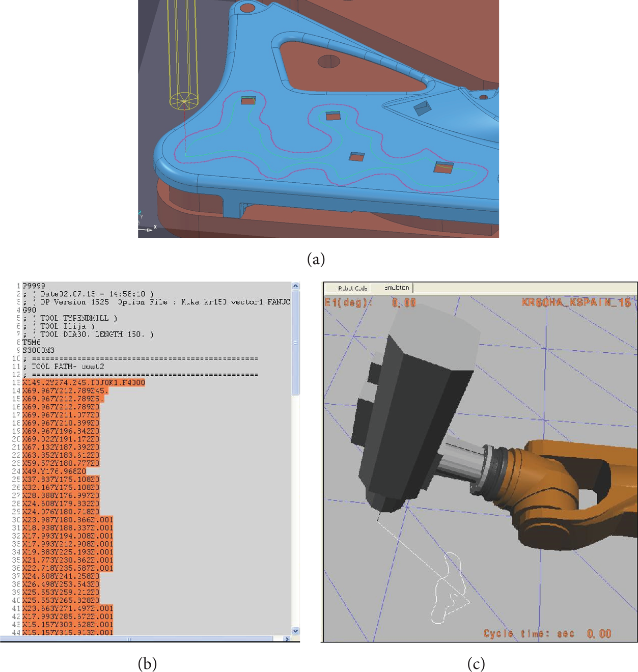
(a) CAM image after Macro execution. (b) Path robot code. (c) Virtual simulation.
A virtual simulation (Figure 16(c)) is performed to avoid collisions of the robot and to assure there are no singularities in the trajectory, and finally the code file in robot language (Figure 16(b)) is sent to the robot controller to be executed. Figure 17 shows the polishing execution sequence.
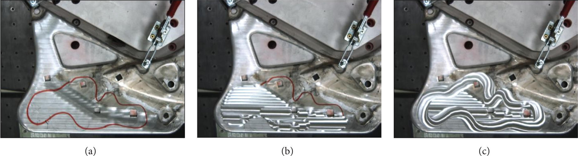
(a) Red contour marking defect area. (b) Defect area repolished. (c) Defect area contour polished.
3. Results and Discussion
Metal part finishing process has no suffered important technology improvements during the last twenty years, and this implies that especially in case of freeform shaped parts [15] a lot of rejected parts are generated during this manufacturing phase.
Defects that make a part to be rejected are mainly derived from the current finishing process. Finishing, grinding, and polishing tasks are still manually performed in the scope of this research. Handmade process reveals problems of repeatability, shape control, amount of material removed [16], and small surface appearance defects. All these problems make that 28% of the parts presented in this research that are currently processed using manual finishing process are rejected. As rejection means reposition of the rejected part, a lot of raw materials and energy consumption are lost in the meantime.
Furthermore, it implies a cost increase for the manufacturer and a reduction in the competitiveness of the industry, that have supposed that, for some younger projects, direct metal finish appearance was dismissed and parts were painted.
On the other hand, 25 parts were processed with the automated system based on robotics and artificial vision and no rejection came about. The initial medium roughness was 2.87 μm with standard deviation of 2.27. The requirement was 1 μm and the values of average reached roughness where 0.62 μm with a standard deviation of 0.28.
An energy consumption evaluation of both traditional and automated processes was done in order to quantify the environmental benefit obtained.
3.1. Traditional Polishing Process Environmental Analysis
Figure 18 represents the whole manufacturing process flow of the part in the research, as it was done in traditional manufacturing production.

Current manufacturing process flow.
With the base of the workflow an energy usage analysis has been done in order to serve as a base to be compared with the new process. Both cases were extrapolated for the production of 1000 correct parts. The part weight is 1485 grams. While information for raw material manufacturing energy consumption was already investigated [17–19], specific process such as automated polishing was not yet studied, so data for this process are taken for the trials done for the research.
The calculations shown in Table 1 are made for producing one good part. In this calculation actual current process data are used. For producing 100 parts, 128 parts have to be polished. 28 of them are rejected and recycled.
I/O data for traditional (manual) polishing environmental impact.

3.2. Proposed Automated Polishing Process Environmental Analysis
In this case, Figure 19 shows the flow chart for the proposed new manufacturing system, including the automated polishing system based on robotics and artificial vision.

Proposed manufacturing process flow, including automated polishing system based on robotics and artificial vision.
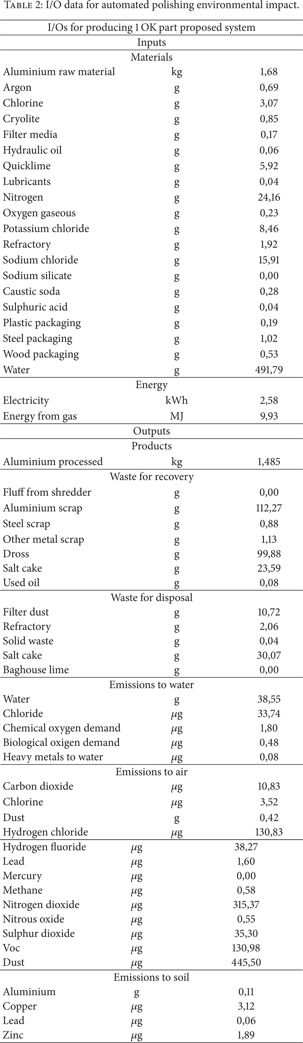
The same I/Os analysis is done (Table 2), using the same methodology, and with information derived from the trials done during the research. 25 parts were finished with the new automated system. None of them were finally rejected. 10 of them were correctly finished in the first full part polishing phase. 15 of them had some defects that were corrected using the defect area automated polishing system (mean time of the correction is 30 seconds).
I/O data for automated polishing environmental impact.
4. Conclusions
Finishing process for tools [20] and parts has been poorly technically developed since the far past. This implies that, despite contributing with a lot of added value to the part manufacturing process, they have been put aside. Quality problems derived from the current manually finishing process involve an inadmissible amount of rejected parts, especially in freeform shaped parts. This situation means that direct polished part surfaces aesthetics will be dismissed in some industrial sectors, as automotive, if no technical improvements are found.
A new process has been developed. It is an inflexion point in the way that will allow the development of new aesthetics to the metal parts, if automated as reliable systems are developed.
The only way to do it is to investigate new automated systems, based on new environmentally conscious technologies, as presented in this paper, that assures that energy saving, waste reduction, and even the reduction of the amount of raw material are required for the industrial process.
During this research a new automated process has been developed that reduces 30% of the energy consumption in the finishing process of the part. Moreover, 20% of the final energy consumption is achieved for the global manufacturing flow chart of the part by means of supporting the improvements in finishing technology with the reduction of the rejected parts that in current process supposes further extra work and energy waste.
Technologically speaking the developed finishing process is faster and more reliable and can serve as a base for the development of new processes. The artificial vision procedure developed and the integration in a robotic environment can be transferred to different manufacturing task, such as deburring, milling, and welding and it could even have application in additive manufacturing sector. The combination of this robotic cell, tool, and methodology is expected to reach mean values of roughness down to 0.11 μm with a standard deviation of 0.04 with zero defects working with flat or big curved freeform surfaces. Further developments are being done for magnesium alloys or carbon fiber composites with epoxy matrix.
Conflict of Interests
The authors declare that there is no conflict of interests regarding the publication of this paper.