
Abstract
Aimed at the established telenanomanipulation system, the method of extracting location information and the strategies of probe operation were studied in this paper. First, the machine learning algorithm of OpenCV was used to extract location information from SEM images. Thus nanowires and probe in SEM images can be automatically tracked and the region of interest (ROI) can be marked quickly. Then the location of nanowire and probe can be extracted from the ROI. To study the probe operation strategy, the Van der Waals force between probe and a nanowire was computed; thus relevant operating parameters can be obtained. With these operating parameters, the nanowire in 3D virtual environment can be preoperated and an optimal path of the probe can be obtained. The actual probe runs automatically under the telenanomanipulation system's control. Finally, experiments were carried out to verify the above methods, and results show the designed methods have achieved the expected effect.
1. Introduction
Micro/nanomanipulation means that assembly can be operated and devices or materials can be moved in the scope of the micro-nano level. With it the pose of the micro/nanomaterials can be controlled and material properties can also be researched [1–3]. Currently, the mainly visual monitoring devices used in mico/nanomanipulation are atomic force microscopy (AFM) and scanning electron microscopy (SEM) [4–7]. AFM has the advantages of force detection and imaging, but the feedback results cannot be obtained real time; thus it is not suitable in the real-time environment. On the contrary, SEM has better function of real-time feedback than force detection. In addition, virtual reality (VR) technology has been applied in a number of micro/nanooperations researches. Sitti et al. used AFM as the operating and imaging tools and developed augmented reality interface in master to improve the accuracy as well as the reliability of operation. The authors also studied the 3D haptic feedback using haptic device [8, 9]. Ando et al. used virtual reality technology to establish a 6D force feedback telenanomanipulation system [10]. Fahlbusch et al. used SEM and their own developed tools to build a nanomanipulation platform based on 2D visualization [11]. In Japan, Tokyo Research Institute studied a method of telenanomanipulation based on VR. The relationship between performance, stability, and scaling factors of velocity and force was studied [12]. However, almost all previous studies used SEM real-time images or AFM images directly. It is obvious that the 2D real-time SEM images are not intuitive, and we cannot get more information directly. So it leads inefficiency experiments and increases the experimental cost while the samples are operated. Thus, studying the method of extract location information from SEM images and probing operation strategy are necessary.
In this paper, the software of SEM telenanomanipulation based on virtual 3D visual and haptic interaction [13, 14] is improved. Nanowires' classifier and probe's classifier are designed by OpenCV; thus the system can quickly and automatically identify and locate the objects in SEM images, and then the region of interest (ROI) can be marked quickly. Through processing the ROI image, the required information for virtual modeling can be obtained. The operation strategies of probe through calculating the Van der Waals forces between the probe and a nanowire are proposed. Through preoperation nanowire in 3D virtual environment, the optimal path of the probe is obtained. Then the actual probe can automatically run under the telenanomanipulation system's control.
2. Telenanomanipulation System
The designed SEM telenanomanipulation system based on virtual 3D visual and haptic interaction technology [14] uses SEM as visual monitoring equipment. The operator can operate the master haptic device (Omega3) to control the slave nanopositioner (Attocube). So the probe in chamber can be moved by nanopositioner. The hardware architecture of this system is shown in Figure 1 and the man-machine interface is shown in Figure 2.
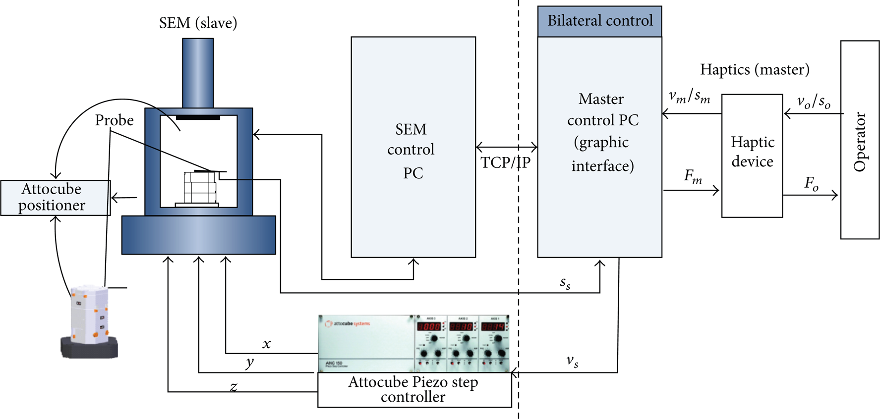
Hardware structure of the master-slave telenanomanipulation.

Software interface of telenanomanipulation system.
Virtual 3D environment in this system is developed to simulate the movement and interaction between nanowire and probe. It intuitively shows the actual process of nanowire manipulation. The required information for virtual environment is extracted from SEM real-time images [15]. This required information is the actual coordinates of the nanowire and probe. Through coordinate conversion, the required information is used to establish the virtual environment. This software interface is developed by Visual Studio 2008 and the technology of OpenGL+Chai 3d is applied to develop the virtual 3D environment. The virtual nanowire and the probe are filled with skeleton spheres.
Since this system works in real-time environment, it needs to process the uploaded SEM images and update the virtual model position in a short time. In the established system, the method of traversal pixels in the whole image leads to poor real-time system. Therefore, to find a more effective information extraction method becomes the priority of this paper.
3. Target Detection Based on OpenCV
OpenCV is an open source of computer vision library. It is written by C/C++ language and paid a lot of attention to real time [16]. There are many machine learning algorithms in OpenCV, such as Mahalanobis, K mean clustering, Bayes classifier, Boosting, and Haar classifier. The algorithm of Haar classifier is generally used for face detection. Besides, it is also good at detecting a particular perspective of rigid object. With the help of the algorithm, we train our cascade classifier.
The cascade classifier works like this: when the object is not found in any cascade of the classifier, the entire calculation is terminated. Only through all cascade would we think the object is detected. This method greatly improves the detection speed and reduces the amount of calculation.
3.1. Classifier Training
The training of OpenCV classifier can be divided into three steps: creating samples, training classifier, and classifier test. We get a series of 2D SEM images in some experiments and select 300 images to obtain the positive and negative samples. Figure 3(a) shows some positive samples of the probe tip. The flowchart of the process is shown in Figure 3(b).

(a) Some positive samples of probe tip. (b) Flowchart of the process.
After training, the nanowires classifier (nano.xml) and probe tip classifier (needle.xml) can be obtained. Afterward, a C++ program is designed to study the accuracy of the classifier. The flowchart is shown in Figure 4. Some results are shown in Figure 5.

Flowchart of the C++ program.
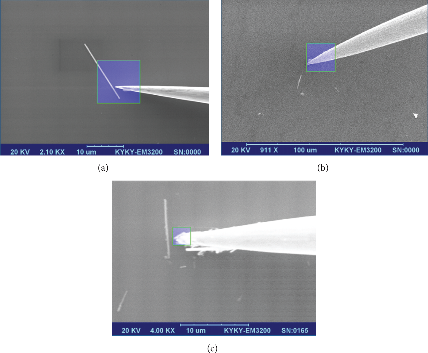
Some results of the test.
From Figures 5(a), 5(b), and 5(c), we can see the probe tip is accurately identified and marked by classifier, especially in Figures 5(b) and 5(c). Although the marked area in Figure 5(a) is bigger, it does not affect postprocessing. After testing 100 samples, only one image which has a complex background is marked as error, so the accuracy is 99%. If complex background in the experiment can be avoided, the accuracy will reach 100%. The nanowires classifier can be tested in the same way.
3.2. ROI Determination and Location Information Extraction
After determining the nanowire and probe regions, the tip region and the two nanowire regions which are near to the tip are selected to construct the ROI. The ROI of Figure 5(a) is shown in Figure 6.

The ROI of Figure 5(a).
The X-Y coordinates of nanowire and probe tip can be determined by traversing the edge pixels in ROI. The Z coordinate of the probe tip can be calculated by the function between Z and image blur degree. Through above methods, the required information of virtual modeling can be quickly acquired. Experiment shows that the time cost is only 35% of the prior method [15]. The program shows the coordinate of probe tip in Figure 5(a) is (375, 284) and the Z coordinate is about 10.1 nm.
4. Probe Operation and Preoperation
Motion planning and coordinated control are important for robot system [17–19]. Because of the influence of scale effect, the adhesive forces hold a dominant position in the micro-nano scales [20]. In order to make the nanowire conduct expected movement, the probe operation strategies and motion path need to be planned.
The relative position of the probe and a nanowire in 3D space is shown in Figure 7(a); some optimum paths are shown in Figure 7(b).

(a) Relative position of a nanowire and probe. (b) Some optimal paths from A to B.
Considering the length of the routine, path 3 is usually selected in the macroenvironment. However, taking into account the force between the probe and nanowire, path 1 can be chosen in the microenvironment. When the probe is far from the nanowire, path 1 can be changed into a relative short path 2. The probe motion in 3D space can be divided into two parts: movement along Z direction and movement in XOY surface.
4.1. Probe Operation along Z Direction
When the probe is far from nanowire, the adhesive force will not affect nanowire's posture. Therefore, the probe operation in Z direction only needs to consider the collision between the probe and substrate. A series of SEM images show that the closer the probe from the substrate, the sharper the probe in SEM images.
According to the above situation, we design a software program to detect the blur degree of probe image. This program can detect the probe image blur in real time. When the operator operates the probe which is close to the substrate in continuous movement (coarse operation), once the blur indicates that the distance between probe and substrate is less than 20 nm, the program will pop up a dialog that reminds the operator to adopt single-step movement (accurate operation). Figure 8 shows the picture when the dialog pops up. This operating mode can not only avoid the probe and damaged samples, but also ensure the safety and improve the efficiency of the experiment.

Blur degree is 47.2080; the Z coordinate is about 20 nm.
4.2. Probe Operation in XOY Surface
The analysis of adhesive force is complex and the Van der Waals force plays a key role in adhesive force. So we just analyze the Van der Waals force. According to Lennard-Jones potential [21], the Van der Waals force between two molecules is

where l0 is the distance between two atoms and ζ/σ is potential parameter. A determines the repulsion strength; B determines the gravity strength. It can be seen that when l0 is larger, the gravity is greater; on the contrary, the repulsion will be greater. According to (1), the force of skeleton spheres in the virtual 3D environment can be set.
Because of the adhesive force between the probe and nanowires within a small range, the probe can be regarded as a small sphere. Figure 9 shows the nanowire-probe position model in 2D space.
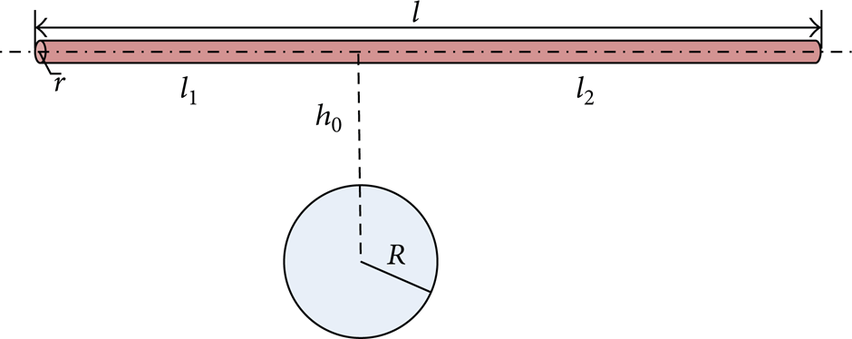
Nanowire-probe position model in 2D space.
The length of nanowire is l, and the probe tip which has an effect on the nanowire is a sphere with radius R. The nanowire is divided into two parts by the center of the sphere's projection, whose length is l1 and l2:

In order to calculate the Van der Waals force between the sphere and cylinder, the force between a point and a sphere is calculated preferentially. The point-sphere model and sphere-cylinder model are shown in Figures 10 and 11.

Point-sphere calculation model.

Sphere-cylinder calculation model.
In Figure 10, h is the closest distance between the point C and sphere, R is the sphere radius, point D is in the sphere, and its coordinate is (x, y, z). If x = ρcos θ and
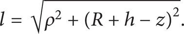
The angle of β is

The range of ρ is
where r0 is the atomic radius of the probe material. If the material of probe is carbon, the atomic radius r0 is 91 pm, σ is 0.34 nm, and ζ is 232.7416 J/mol. If R is 1 um, the force between a point and the carbon sphere is shown in Figure 12. As can be seen from Figure 12, when h is greater than 0.2 nm, the force is about zero.

Van der Waals force between a point and a carbon sphere.
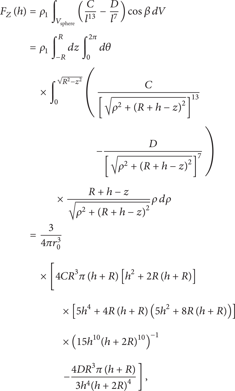
The force between a sphere and a cylinder is

where
From (5), we can get that when h is 2.5σ, the force is zero. So the point C in Figure 7(b) must be more than 0.85 nm from the nanowire. According to (6), if k is bigger than 0.5, we can easily get FZ2 > FZ1. Considering the force between nanowire and substrate, the nanowire will tend to do anticlockwise rotation. To make nanowires rotation, you may need to touch the nanowires by the probe.
Thus the operator can operate the probe approaching the nanowire through path 2; when the distance between point C and the nanowire is about 1 nm (bigger than 0.85 nm), stop the probe movement in the Z direction. Then move the probe to the middle of the nanowire when the nanowire makes translational motion; otherwise, the probe should be moved to the side which is to be rotated. But when the nanowire is too long, this method will fail.
4.3. Preoperation in the Virtual Environment
After the virtual environment is automatically established using the extracted position information, the operator can use the operating strategies to make the virtual probe conduct expected movement. At the same time, the system will record the virtual probe path in a text file. An optimal path will be achieved after several operations. If the automatic execution order is confirmed, the system will read the optimal path parameters to control the actual probe's movement. Thus the actual probe automatically runs under the system's control. The operation process is shown in Figure 13.
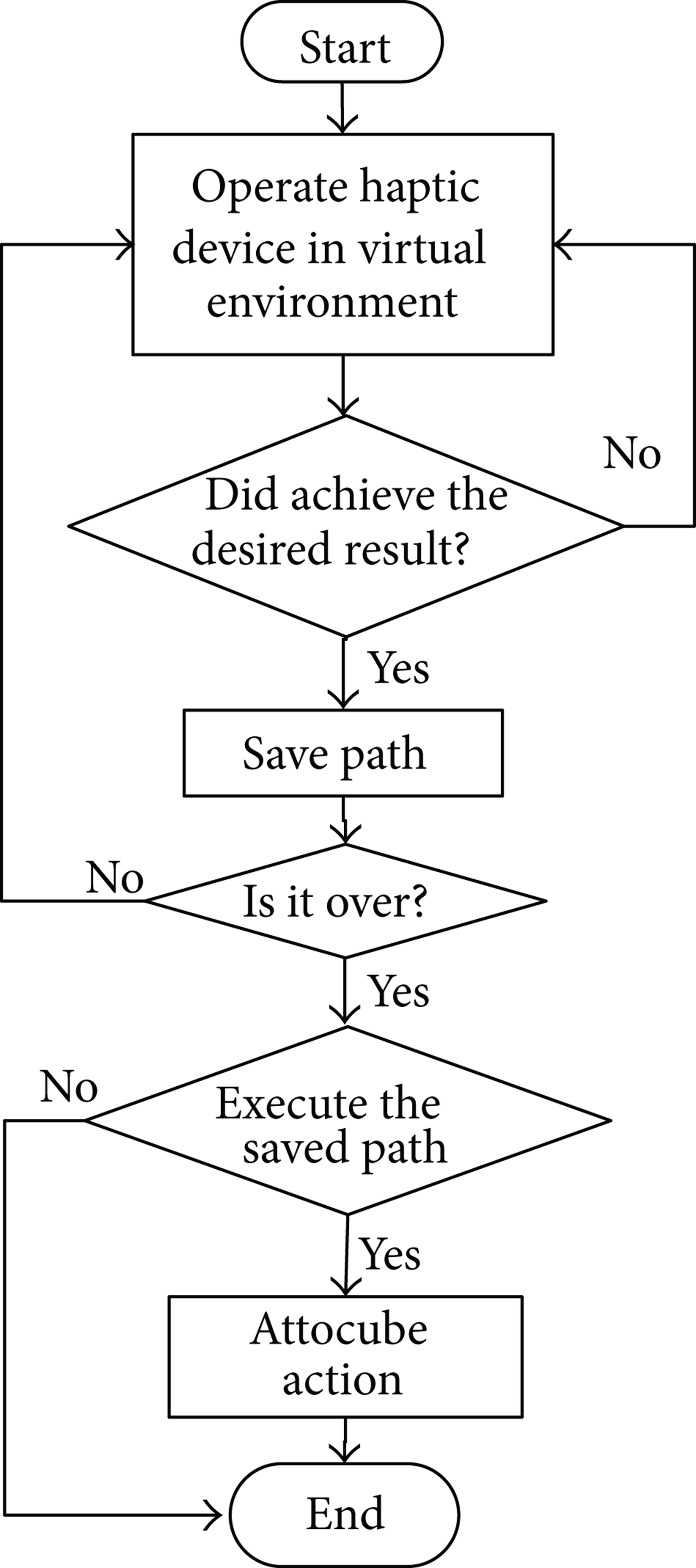
The operation process.
5. Simulation and Experiments
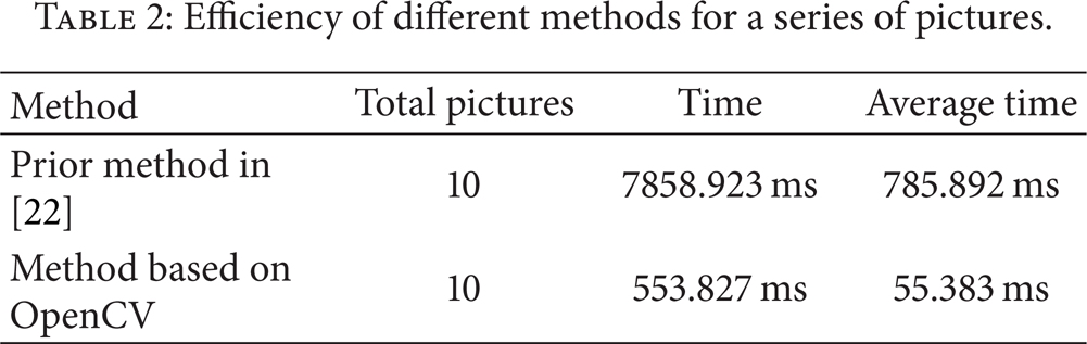
After updating the program codes of the system, following experiments are carried out. Firstly, the efficiency of different pose information extraction methods for the same SEM images (shown in Figure 14) is compared. The results are shown in Tables 1 and 2. It can be seen that the new method is 10 times faster than the prior one in [22].
Efficiency of different methods for single image.

Efficiency of different methods for a series of pictures.

Four pictures used in test I.
Secondly, the developed SEM image processing algorithm is applied to extract the probe and nanowire position. Then the position information is used to establish the virtual environment. The results are shown in Figure 15. We can see the virtual environment automatically established by the extracted position information. But the length of the nanowire is inconsistent, because the virtual modeling of nanowires is not perfect. This is our future work. Finally, the probe operation strategies along Z direction and in XOY surface are performed. Using these strategies, the probe path plan is achieved.
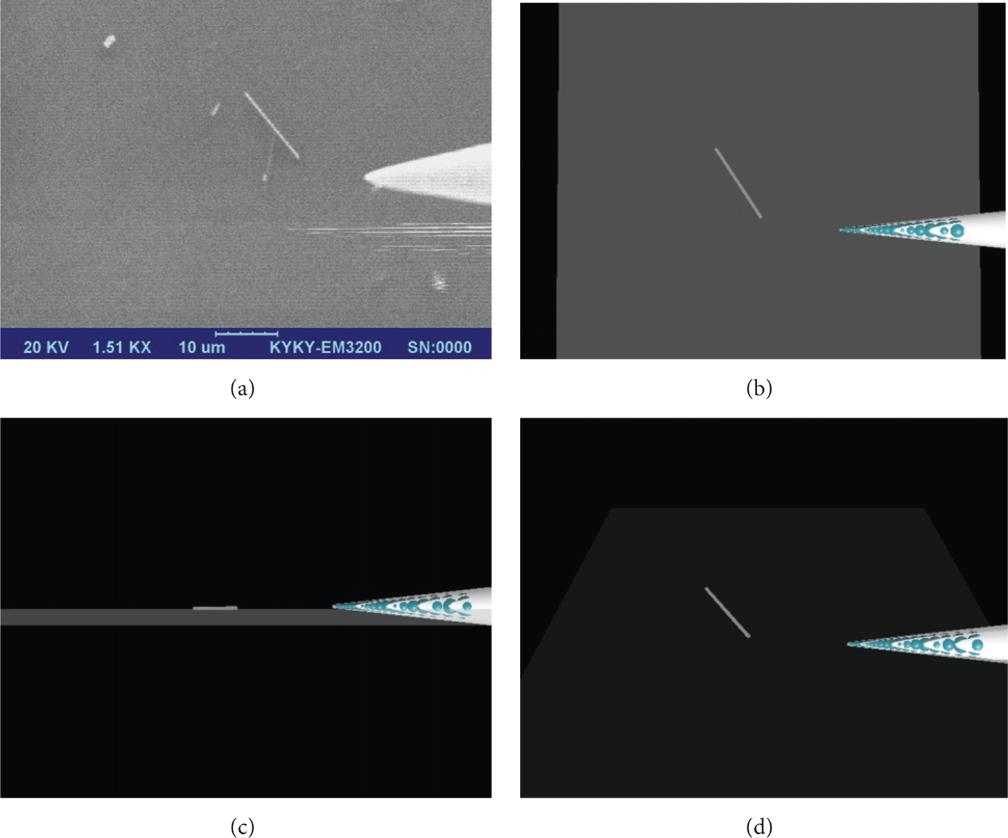
(a) SEM picture. (b) Virtual environment from Z direction. (c) Virtual environment form X direction. (d) 40 degrees from X direction.
6. Summary
This paper mainly carried out the following work. Firstly, a classifier of nanowires and probe was designed with OpenCV, so the probe and nanowires in SEM images can be automatically identified and located by the system. After the ROI was identified and marked, position information of nanowire and probe can be quickly obtained. Secondly, the operation of probe was realized. The operator employs the operation strategies and makes the virtual probe conduct expected movement; then an optimal path can be obtained. At last, the above designed experiments were conducted in our virtual environment. The results show that the corresponding method has achieved the expected effect. Further research of fast and precise updating of the nanomanipulation virtual environment will be devoted.
Conflict of Interests
The authors declare that there is no conflict of interests regarding the publication of this paper.
Footnotes
Acknowledgments
This work was supported partially by the National Natural Science Funds for Young Scholar (Grant no. 51105117), Natural Science Foundation of Heilongjiang Province (Grant no. QC2014C054), Foundation for University Young Key Scholar by Heilongjiang Province (Grant no. 1254G023), and Postdoctoral Science Research Foundation of Heilongjiang (Grant no. LBH-Q13094).