
Abstract
This research presents a new systematical design approach of foldable structure composed of several rhombic elements by applying genetic algorithm. As structural shapes represented by a foldable structure can be easily and dramatically morphed by manipulating rotational directions and angle of joints, the foldable structure has been used for various elementary structural members and engineering mechanisms. However a systematic design approach determining detail rotational angle and directions of unit cells for arbitrary shaped target areas has not been proposed yet. This research contributes to it by developing a new structural optimization method determining optimal angle and rotation directions to cover arbitrary shaped target areas of interest with aggregated rhombic elements. To achieve this purpose, we present an optimization formulation minimizing the sum of distances between each reference joint of an arbitrary shaped target area and its closest outer joints of foldable structure. To find out the outer joint set of a given foldable structure, an efficient geometric analysis method based on Delaunay triangulation is also developed and implemented. To show the validity and limitations of the present approach, several foldable structure design problems for two-dimensional arbitrary shaped target areas are solved with the present optimization procedure.
1. Introduction
This study presents a new systematic design approach of foldable structure or mechanism covering arbitrary shaped target areas. Foldable structure can be constructed simply with repeated unit cells composed of rigid links, ropes, revolute, pivot joints, and scissor hinges; for an example, Figure 1 shows a typical example of a foldable structure—a luggage elevator used in airport. Due to its simplicity in designing and manufacturing, foldable structure has been used in many studies for various engineering applications such as temporary protective covers, antennas and radio towers, emergency shelters, lightweight camping, bridges, hospital, and other public buildings. Some benefits of foldable structure from an engineering point of view may be the fastness, the easiness in deployment and transportation, and the deformability in terms of geometry (morphing from one structure to anther shape structure). In short the simplicity and the deformability of a folding structure or a mechanism regardless of construction site are important features and characteristics of folding mechanism. Nevertheless except some popular and available folding structures, it is often difficult to determine the configuration parameters such as angle and rotation direction of folding structure. In other words, it is not straightforward in determining the geometric parameters of relative complex folding structure. To contribute this aspect, this research tries to develop a new systematic design optimization approach to improve the deformability of folding mechanism to cover arbitrary shaped target areas or to be installed at any construction site.

Luggage elevation foldable structure. (a) An example of a foldable structure in airport luggage elevation, (b) a unit cell of the foldable structure, and (c) an elementary structure with rigid links and joints for the foldable structure of (a).
To design an optimal repeated internal unit cell or a foldable structure, a number of studies have been carried out (see [1–6] and the references therein). You and Pellegrino presented a new general type of two-dimensional foldable structure [1]. Benjeddou et al. presented an innovative concept of a foldable composite beam made of wooden blocks [2]. Zanardo illustrated a new concept of the geometry and the kinematics of two articulated systems [3]. Hoberman developed a new simpler angulated element consisting of rods and scissor hinges and presented many applications of their foldable structures [4–6]. Viquerat et al. used a plane symmetric Bricard linkage for developing a deployable structure and the internal mechanism of the structure is described in terms of its Denavit-Hartenberg parameters [7]. Based on the mechanism theory, Zhao et al. investigated the application of deployable structure (folding structure) based on scissor-like element (SLE) for a foldable stair [8, 9]. Also Cai et al. studied Hoberman's linkage [10] and Kempe suggested a new foldable structure using four-piece linkage [11]. From our review of these literatures, it is found that although many analytical and numerical methods have been proposed to design a unit cell of folding structure, there are few design approaches concerning how to assemble unit cells and how to determine geometric configuration parameters (angle and positions) to cover arbitrary shaped areas. For a practical example, let us assume that we need to repair some destroyed parts of space shuttle, nuclear power plants, oil pipe in deep sea, or submarine pipeline without waste of time and risk factor [12, 13]. Without knowing the shape or area of damaged part, a robot without multihazard risk to human life can be urgently deployed in space, damaged nuclear power plant, or damaged parts of deep sea and it can take emergency measures with foldable structures before permanent repairmen. But in those emergency situations, often the shapes and conditions of damages are unknown that makes it hard to repair damages. Therefore we have a plan to make an intelligent and robust robot that can detect shapes of destroyed parts with IR image cameras or electromagnetic sensors and can make fundamental frames with folding structures with artificial intelligence for the sake of sealing and contaminated water-drainage. This kind of technology has been also important after the accident of nuclear power plants in Russia and Japan and to every country having submarines, nuclear power plants, or space satellites. Here it should be noticed that the shape or area of destroyed parts is now known a priori. It is our proposition that even in these situations, with the help of the deformability of folding structure, a robot can deliver some standard basic folding mechanisms with repeated unit cells, that is, 2 by 2 or 3 by 3 folding structure, and the present design approach can be used to determine the geometric configuration parameters which make the folding mechanisms fit to target holes and the robot can imminently repair the breakdowns.
To develop a systematic design method, the geometric configuration called a rhombic element of Figure 2(a) proposed by Tanaka et al. [14] in Figure 2 is considered. In Figure 2, the assembly of 4 rhombic elements of Figure 2(b) is called 4RE-linkage and the assembly of four 4RE-linkages is called a 2 by 2 foldable structure. In their study, they focused on establishing the relationship between the overall deformability and the spatial location of planar structure. As an extension to these relevant researches, this study focuses on how to efficiently and effectively determine the geometric configuration parameters to adjust the outline shape of a foldable structure especially for arbitrary shaped areas. As the optimization problem is inherently nonlinear and has many local optima, the genetic algorithm method becomes a natural choice in this study. Specifically the rotational directions of joints and their magnitudes are parameterized by binary design variables (0 or 1) and integer variables, respectively. From an optimization point of view, the objective function is set to the sum of distances between each reference point and its closest outer node point of a foldable structure of interest. If the objective value is converged to zero, in principle the foldable structure with the optimized design variables can exactly fit the outlines of the arbitrary shape areas of interest. To our best knowledge, however, it is found that it becomes a tricky task to determine the outer joints defining the outline of the foldable structure as a set of its outer joints is subject to be changed. In order to determine the set of outer joint points, this research presents a new numerical approach based on the Delaunay triangulation method [15].
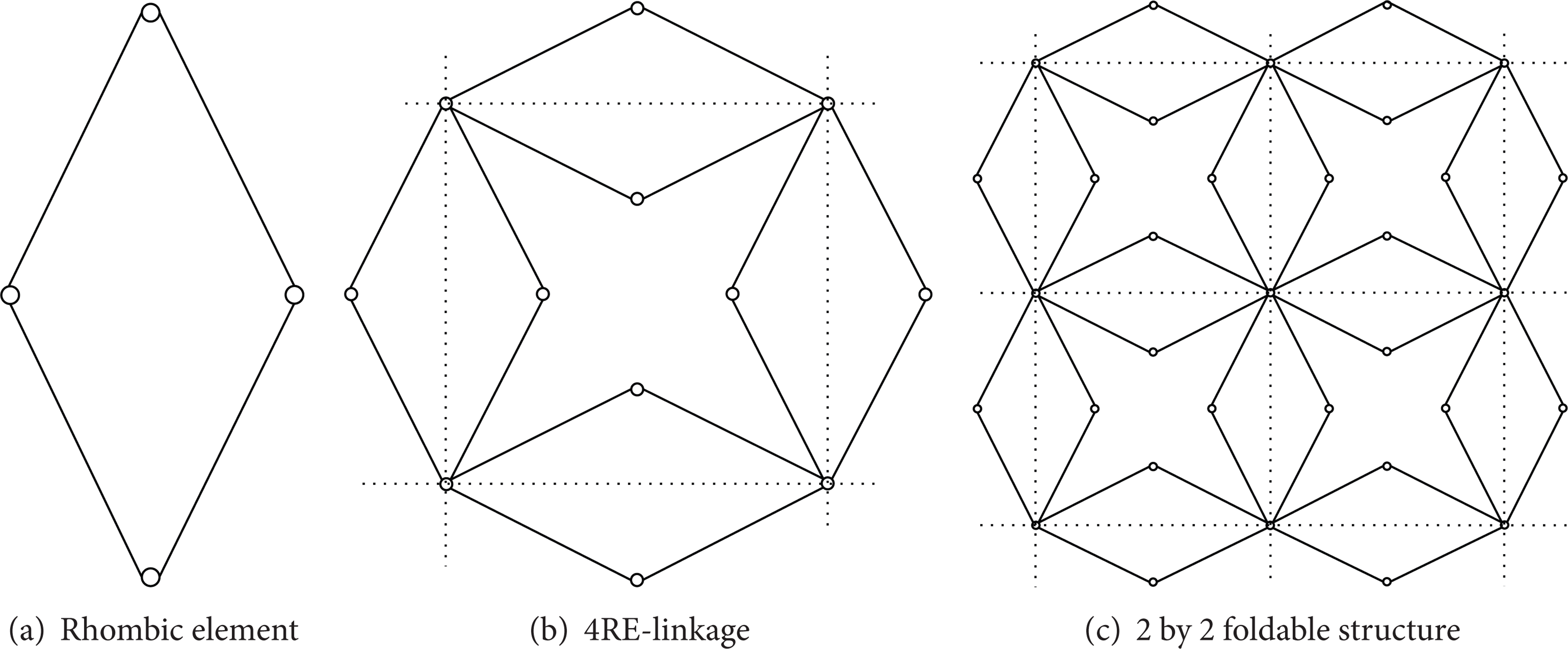
(a) Unit cell of foldable structure considered in this research, (b) 4RE-linkage, and (c) 2 by 2 foldable structure.
This paper is organized as follows. The basic kinematic analysis of foldable structure which is composed of repeated unit cell of rigid-body mechanism is given in Section 2. A parameterization based on the kinematic analysis and a new optimization problem formulation using binary and integer design variables are described in Section 3. In Section 4, several numerical examples of designing foldable structure are presented to validate the proposed design approach. Finally, our findings and new topics for further research are discussed and summarized.
2. Kinematic Analysis of Four Rhombic Elements Based Foldable Structure
Figure 3 shows the four-rhombic-element linkage (4RE-linakge) formed by 16 equilateral and rectilinear bars for 4 unit cells [14]. The 16 identical straight bars are connected for eight 2-bar and for four 4-bar linkages. Due to the simplicity of the 4RE-linkage in geometry as well as in manufacturing, it has been used as a basic constructing element for a various engineering structures by changing its geometrical configuration [14]. To explore its versatility from a geometric point of view, the kinematic analysis of 4RE-linkage can be conducted as shown in Figure 3.
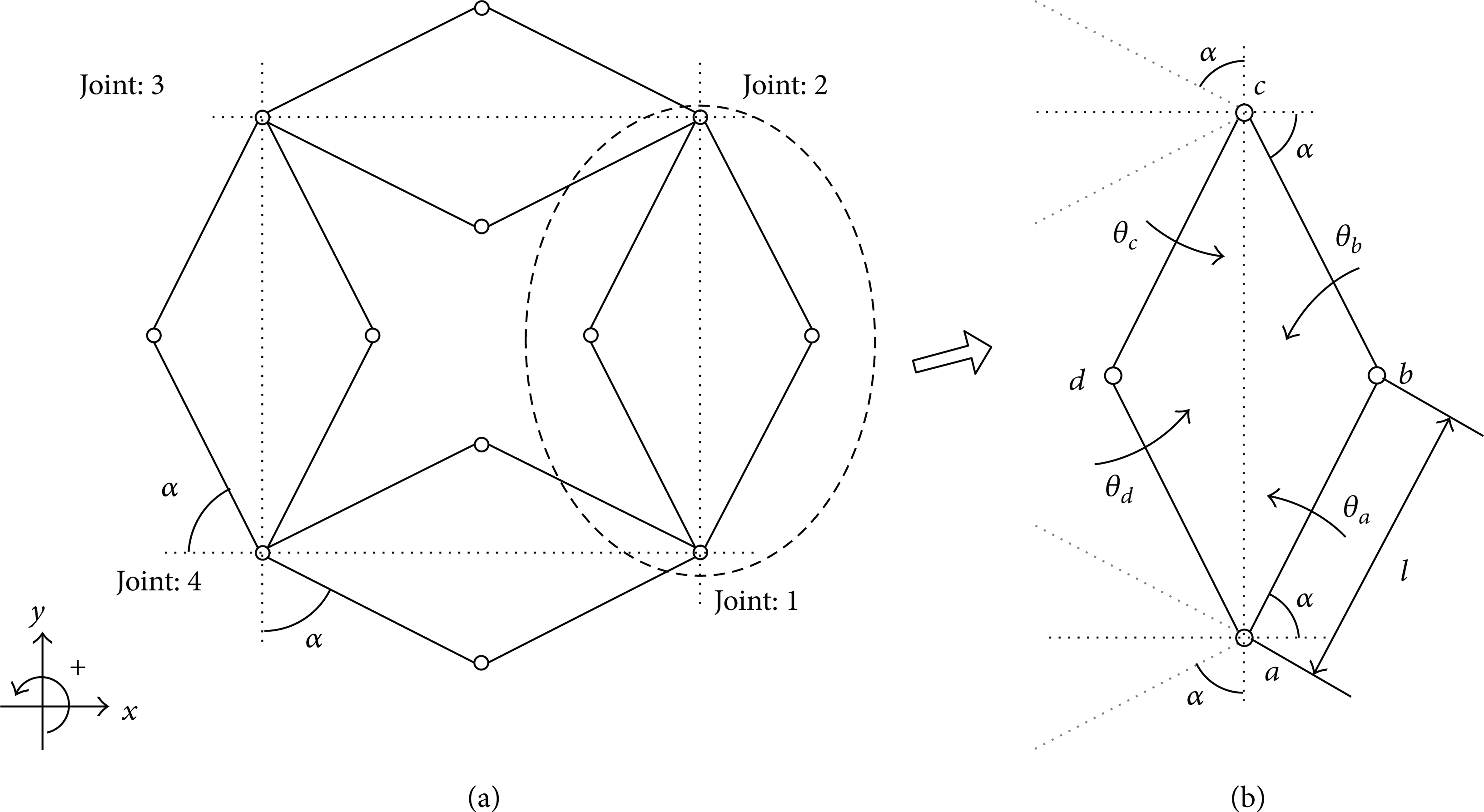
A repeated building block: 4RE linkage. (a) A repeated mechanism building block (4RE linkage consisting of 4 rhombic elements) and (b) a representing rhombic element and its geometric notations.
2.1. Kinematic Analysis of a Rhombic Element
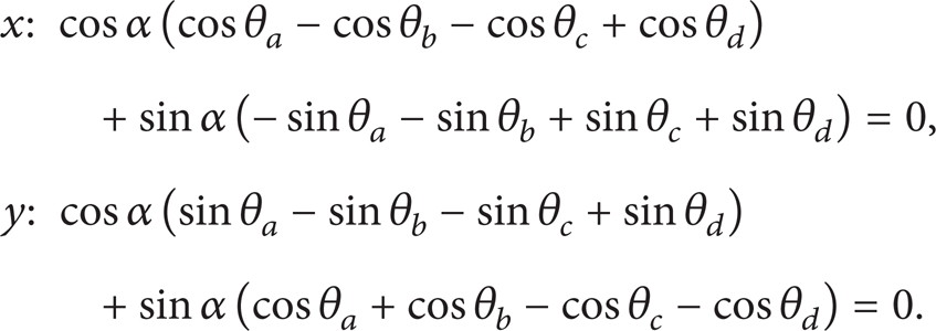
Note that the kinematic analysis of a basic rhombic element in Figure 3(b) provides some essential mathematical and theoretical foundations in utilizing the various rigid body motions of various foldable structures. Obviously the basic geometric configuration of the rhombic element is determined by the length of rigid bar l and the angle α of the component links (see Figure 3(b)). An investigation of the rhombic element of Figure 3(b) turns out a loop close equation,

For the sake of simplicity, (1) can be rearranged in terms of the rotational angle α:
From the above two geometric compatibility conditions, an important notation of rotational modes regardless of the rotational angle α in the range from 0 to π/2 can be introduced in [14]:

The above geometric compatibility conditions, (3), result in the following 4 rotational modes of the rhombic element [14]:

where the four rotational modes are denoted by
2.2. Kinematic Analysis of 4RE-Linkage
Based on the notations and the analysis procedures for the RE in the precedent section, the kinematic analysis procedure and the planar deformation mobility of the foldable structure of Figure 5 can be analyzed similarly [14]. Refer to Figure 5 for the angle notations employed for the 4RE-linkage.
As this foldable structure consists of the 4 rhombic elements of Figure 4, the rotational parameters can be defined. In Figure 4(b), the repetitive assemblage can be defined by attaching the joint 1 of one repeated building block to the joint 3 of an adjacent repeated building block. Similar to this, the joint 2 can be attached to the joint 4 of an adjacent repeated building block:
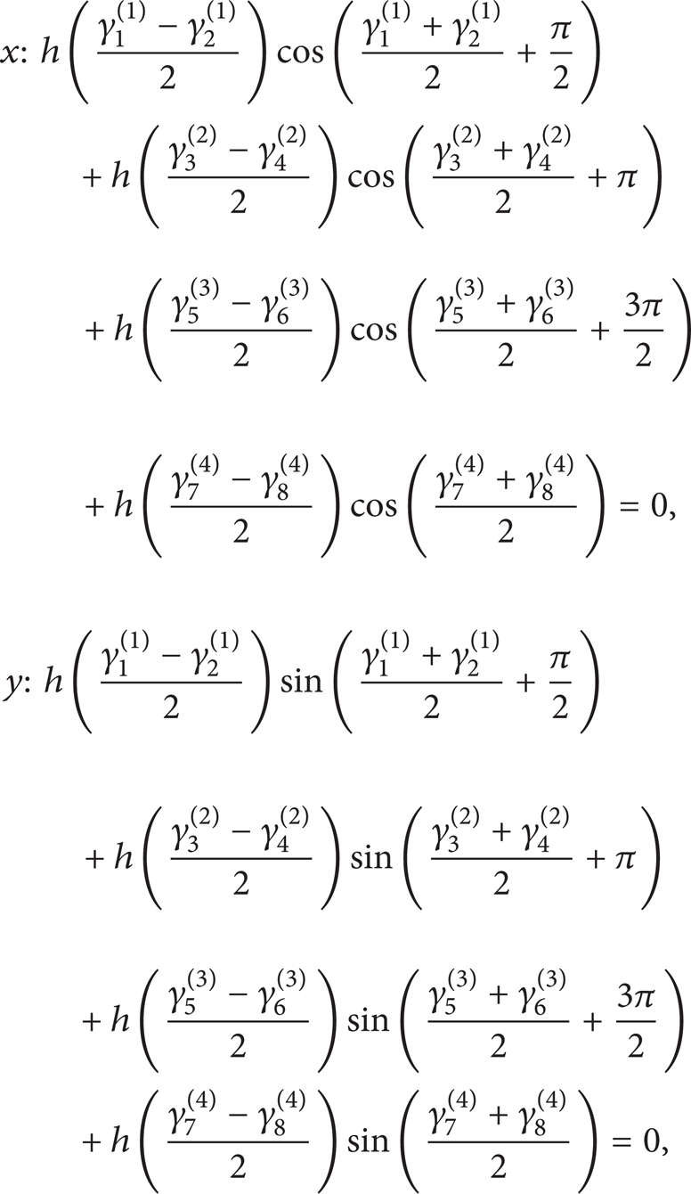
where γ
i
(j) represents the rotational angle of the ith joint of the jth link in Figure 5 and h is a function of the segment
Similar to the kinematic analysis for the rhombic element, (5) can be rearranged in terms of α in 0 ≤ α ≤ π/2 to find out its rotational modes as follows:

By analyzing (7), the following geometric constraints can be obtained:

Then the following 8 rotational modes from γ0 to γ8 can be obtained for the 4RE-linkage as follows:
Any motion of the 4RE-linkage can be described by the scaled sum of the rotational modes of (9).

The assembling repeated building block. (a) The foldable structure consisted of the 4RE linkage and (b) the repetitive manner to construct a foldable structure.

A 4RE-linkage: repeated rhombic blocks. (Note that the rotational angles are denoted by γ i (j) for the rotational angle of the ith joint of the jth link rather than θ in (4).)
2.3. Complex Motions of a Foldable Structure
2.3.1. Rhombic Element and 4RE-Linakge
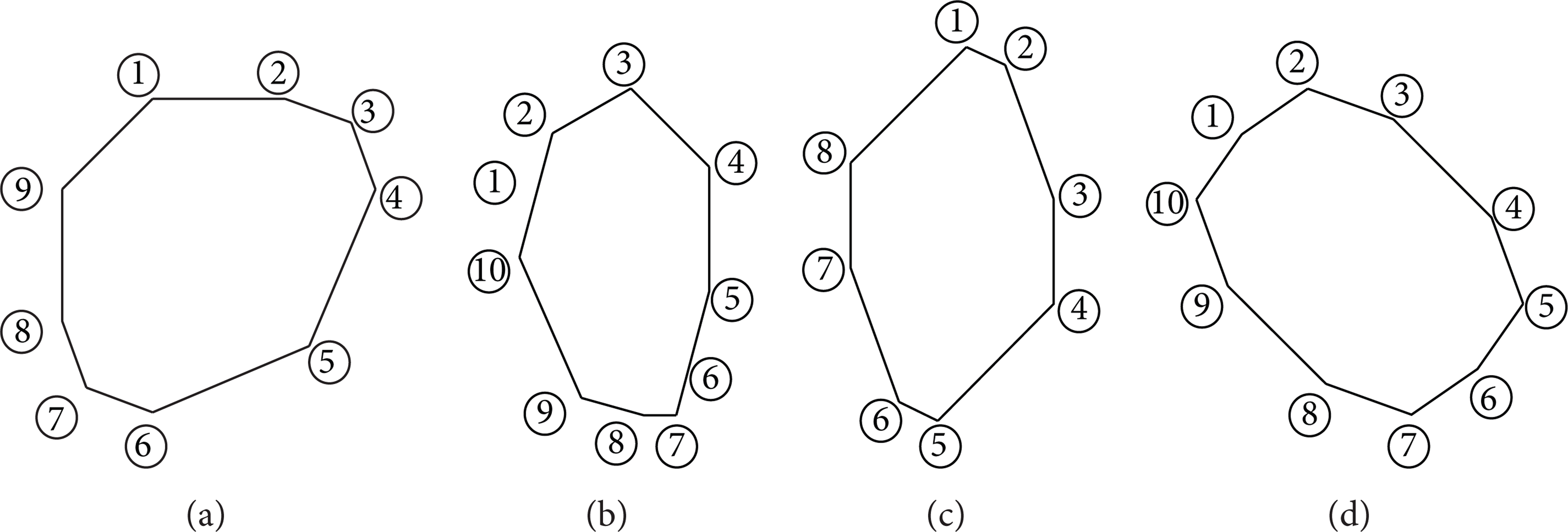
This subsection aims to show that it is tedious and difficult to predict the motions of the rhombic element, that is, the 4RE-linkage and the foldable structure (here 2 by 2 4RE-linkage) with the given geometric parameters. First of all, as studied there are only the four rotational modes for the rhombic element of Figure 6. The motions can be visualized easily by using few modes and rotational angle of the rhombic element. For an example, Figure 6 shows some motions of the rhombic element according to the changes of a step size angle β with an arbitrarily chosen 50 degrees for α. Here all the step size angles of the links are set to β and the rotational angle can be expressed as follows:

As the motion of the rhombic element is under the pure rotation with β degrees, it is easy to describe and visualize. On the other hand, Figure 7 represents the five rotational modes of the 4RE-linkage with α = 50° and Figure 8 represents three rotational modes of 4RE-linkage with α = 45°. As shown, the motions of 4RE-linkages become more complicated than the case of one rhombic element.
Several motions of a rhombic element. (a) The structures with the mode = [+1 +1 +1 +1] and β = 0°, 30°, 60°, 90°, (b) the structures with the mode = [+1 −1 +1 −1] and β = 0°, 30°, 60°, 90°, (c) the structures with the mode = [+1 +1 −1 −1] and β = 0°, 30°, 60°, 90°, and (d) the structures with the mode = [+1 −1 −1 +1] and β = 0°, 30°, 60°, 90°.

Several motions of 4RE-linkages using α = 50° and five different modes.

Several motion of 4RE-linkages using α = 45° and three different modes.
2.3.2. 2 by 2 Foldable Structure
To show a more complex case, we constructed 2 by 2 foldable structure first. By setting α = 50° in Figure 9 and α = 45° in Figure 10, several rotational modes are plotted with some arbitrarily chosen step angle, β. See that while the motions of the 2 by 2 foldable structure with α = 50° can be predicted because they are similar to the motions of 4RE-linkages, the motions with α = 45° are almost impossible to predict by just observing the shapes of 4RE-linkages. In short, through the observations of the motions of the rhombic element, the 4RE-linkage, and a 2 by 2 foldable structure, it is nearly impossible to predict and design the motions of an arbitrary foldable structure by engineer's intuition. It is our proposition that a systematic design approach is required and the next sections will develop a new method and prove its validity in designing several structures. In addition, it should be mentioned that, as described in [14], mechanisms can be assembled with special joints and rigid bars. For example, when a mechanism has 45 degrees for α + β as shown in Figures 8 and 10, the overlapping between rhombic elements occurs. To avoid overlapping, some special type joints should be adopted. Refer to [14] for the assemblage without the overlapping among components.

Several motions of foldable structure assembled by 2 by 2 4RE-linkages using α = 50° and five different modes.

Motions of foldable structure assembled by 2 by 2 4RE-linkages using α = 45° and three different modes.
3. Structure Optimization Formulation for Foldable Structure
In Section 2, the assemblages of some element building blocks show complex movements and their covered areas are subject to be changed dramatically by changing their geometric parameters, that is, the rotational direction and the magnitudes of angles of rigid bars. From an engineering point of view, this geometric feature can be exploited for various engineering purposes such as the application of robotic movement for complex and undetermined hazard environments, the application for the structural damage management of a larger structure, or just the application of toy.
We also notice that the predictions of the mobility and the covered shape of a foldable structure are tedious and heuristic. Therefore it is preferred to develop a systematic and robust design approach based on some engineering optimization theories for this purpose. By detecting and measuring the approximated shapes of areas and applying a systematic and robust design approach to determine the geometric parameters of a basic foldable structure, we can obtain the geometric parameters of the foldable structure to make its shape fitted to target shapes. To do this, at first we define the binary and the integer design variables for the rotational directions of joints and the magnitudes of angles. To make the shape of a foldable structure to a shape of interest matched, the optimization method presented in this research can be applied. Here it was an important issue to efficiently classify joints defining the outline of a foldable structure.
3.1. Parameterizations of Rotational Direction of Joints and Magnitudes of Rotation Angles
The rotational directions of joints and the magnitudes of angles in Figure 11 are parameterized with the binary and the integer design variables, respectively. Because there are eight rotational modes of the considered foldable structure, three-digit binary design variable is needed to represent the rotational modes. The three-digit binary design variable will represent eight rotational modes as follows. The design variable can be represented by the integer design variable range from 1 to 8 naturally; however, the binary design variable is used in this research:
According to (11), the eight rotational modes will be selected according to the changes of binary design variable

Unlike the rotational direction, the magnitudes of initial joint angle and joint step size angle are parameterized with the integer design variables α and β, respectively. Finally, the binary variables and the integer variables vary from 0 degree to 90 degrees with one degree step which will be used as design variable in this research; the magnitude of the step angle can be smaller or larger but this research adopts this value to verify the effectiveness of the present algorithm:

The above rotational directions of joints, the initial joint angle, and the joint step size angle in (11) and (13) are depicted in Figure 11. Note that last three rotational modes,

Parameterization of the rotational direction of joints and the magnitude of the angle. (a) A rotational direction of joints and (b) the magnitude of the joint angle.
3.2. Outer Joint Detection by the Delaunay Triangulation
It is crucial to find out the outer joints determining the outline of a foldable structure efficiently and effectively. To do this, a new technique based on the Delaunay triangulation is developed. To make it clear, let us consider a foldable structure in Figure 12(a) which may be regarded as one design obtained during an optimization process and its Delaunay triangulation is shown in Figure 12(b). After this Delaunay triangulation, the information of the edges of the triangles is utilized to find out the joints defining outlines. In other words, we can select some edges of triangles which are shared by only one triangle as shown in Figure 12(c) for the outline edges and the joints defined by the edges as shown in Figure 12(b).

An example of the outer joint detection process during optimization. (a) A given foldable structure, (b) a Delaunay triangulation of the structure, (c) the boundary edges extracted from the Delaunay triangulation, and (d) the outer nodes from the boundary edges.
3.3. Optimization Problem Formulation
To find out the optimal design parameters of (13) with which a foldable structure covers an arbitrary shaped area, a proper optimization problem should be formulated. To achieve this, this research chooses the rotational directions and the rotational magnitudes are optimized with the following optimization formulation. The objective function is to minimize the summation of the distance values between each reference point of the target area and its closest outer joint of a foldable structure as follows:
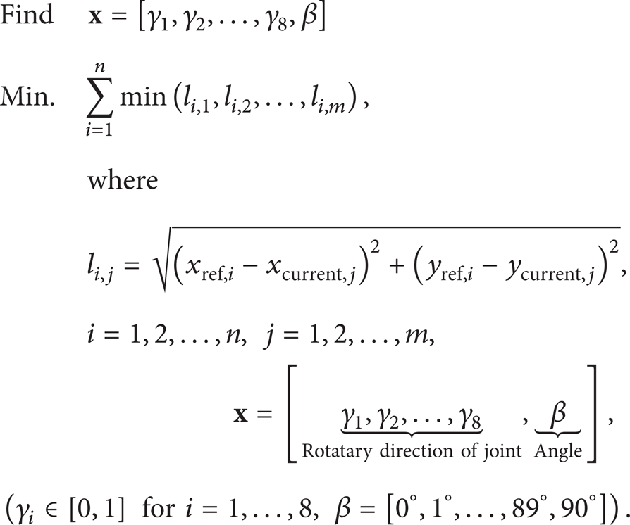
The distance between the ith reference joint and the jth outer joint is denoted by li, j. The total number of the reference points defining the outline of the target area and the total number of the outer joints are denoted by n and m, respectively. See Figure 13 for the meanings of the distance definition and the objective function. Obviously before an optimization process, the objective function has a large positive value. As an optimization goes by in the framework of the genetic algorithm, the objective function is decreased and its corresponding area will be similar to the target area. Here note that there can be many local and global optimum solutions. Therefore the population based optimizer can be one of the optimizers. And the initial configurations of the rhombic elements influence the optimization processes. For an example, to cover some areas, we can use 2 by 2, 3 by 2, or other rhombic elements. Therefore it should be determined by an engineer what kind of rhombic elements is adopted. Furthermore the target points should be chosen considering the type of the employed rhombic element.

The meanings of the distances and the objective function (the reference joint and the current outer joint are denoted by R i and N j , resp.).
To successfully solve the optimization problem with the binary and the integer design variables, a genetic algorithm (GA) is one of the most suitable algorithms for the structural optimization of foldable structure [15].
3.4. Optimization Formulation: Genetic Algorithm
The design variables of the present design method are binary and integer design variables; a genetic algorithm (GA) is one of the most suitable algorithms for the optimum design optimization of foldable structure [15]. Note that the GA algorithm should optimize the binary design variables parameterizing the rotational directions of joints and the integer design variable parameterizing the step size of angle which requires some extensions of generic genetic algorithm. In this research, we adopt a GA code implemented in Matlab as shown in Figure 14.

Flow chart of the genetic algorithm.
4. Design Optimization Examples
4.1. The 2 by 2 Foldable Structure Design Examples
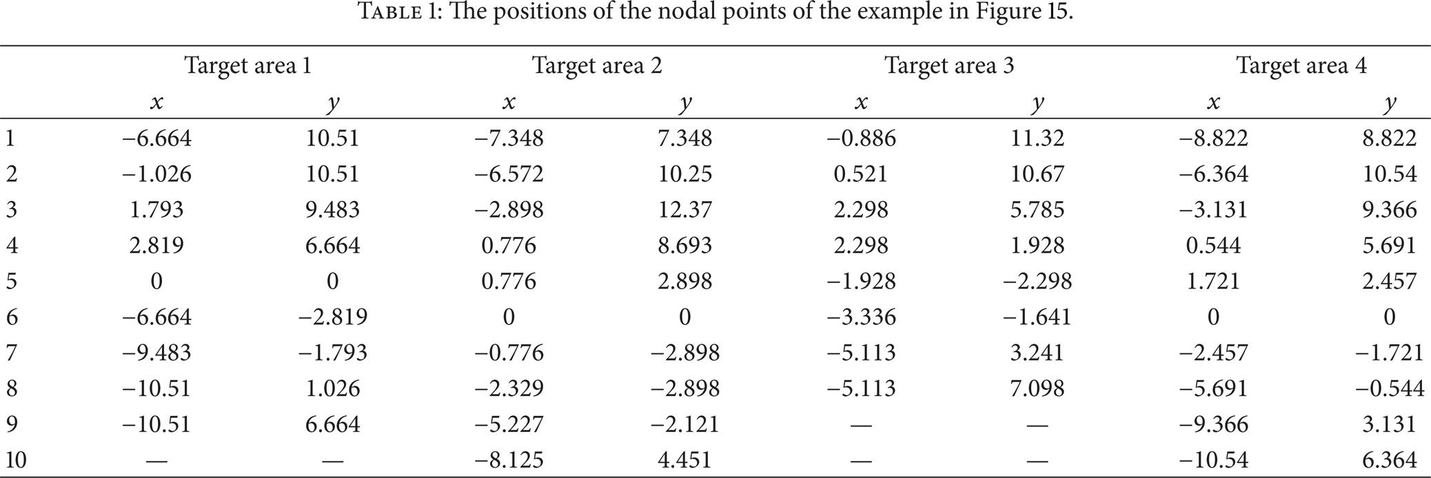
For the first numerical example, the optimized directions and angles of a 2 by 2 foldable structure covering the four target areas in Figure 15 are optimized. The number of individuals and mutation rate for the genetic algorithm are set to 100 and 0.09, respectively. The target areas are randomly chosen by manipulating the 2 by 2 foldable structure before optimization in order to guarantee the existence of optimal solutions. As expected, the various shapes can be covered by the foldable structure and the detail positions of the four designs are given in Table 1. The developed optimizations linked with the foldable mechanism analysis in the framework of the constraint force method are conducted in Figure 16. As shown the four designs covering the target areas can be found successfully with the genetic algorithm. These examples prove that the developed algorithm can find out the optimum designs covering target areas.
The positions of the nodal points of the example in Figure 15.
Four target areas of interest for the 2 by 2 foldable mechanism. (a) Target area 1 (

Optimization results for a 2 by 2 foldable structure. (a) An optimized foldable structure for the target area 1 and its convergence history (
4.2. The 3 by 2 Foldable Structure Design Examples
In addition to the optimum design of the 2 by 2 foldable structure, the developed algorithm can easily consider a more general foldable structure. To show this feature, the 3 by 2 foldable structure is chosen as a basic foldable structure and the optimization problems of Figure 17 are considered. As in the first numerical examples, the target areas are chosen by manipulating the 3 by 2 foldable structure a priori and the number of individuals and mutation rate for the genetic algorithm are set to 100 and 0.09, respectively. Compared with the covered areas of the 2 by 2 foldable structure, that of the 3 by 2 foldable structure can represent more detailed and smoothed structures of the target areas as expected. The design optimization results for four target areas and the optimization convergence history are shown in Figure 18. After the optimization, all of the objective values for four problems are converged to zero. The detail positions of the four mechanisms are given in Table 2.
The positions of the nodal points of the example in Figure 17.


Four target areas of interest for the 3 by 2 foldable mechanism. (a) Target area 1 (

Optimization results for a 3 by 2 foldable structure. (a) An optimized foldable structure for the target area 1 and its convergence history (
4.3. The Design Examples Using Arbitrary Assemblies
At the first and the second numerical examples, the applications of the 2 by 2 and the 3 by 2 foldable mechanisms are solved by the present approach. Through these two numerical examples, we observed that it is possible to find out some optimal foldable mechanisms covering some complex target areas. Now to see the applicability of an arbitrarily chosen mechanism, the target areas of Figure 19 are considered. Unlike the previous two examples, the areas are chosen for the arbitrary assemblies of the rhombic elements. And the optimum designs are shown in Figure 20.
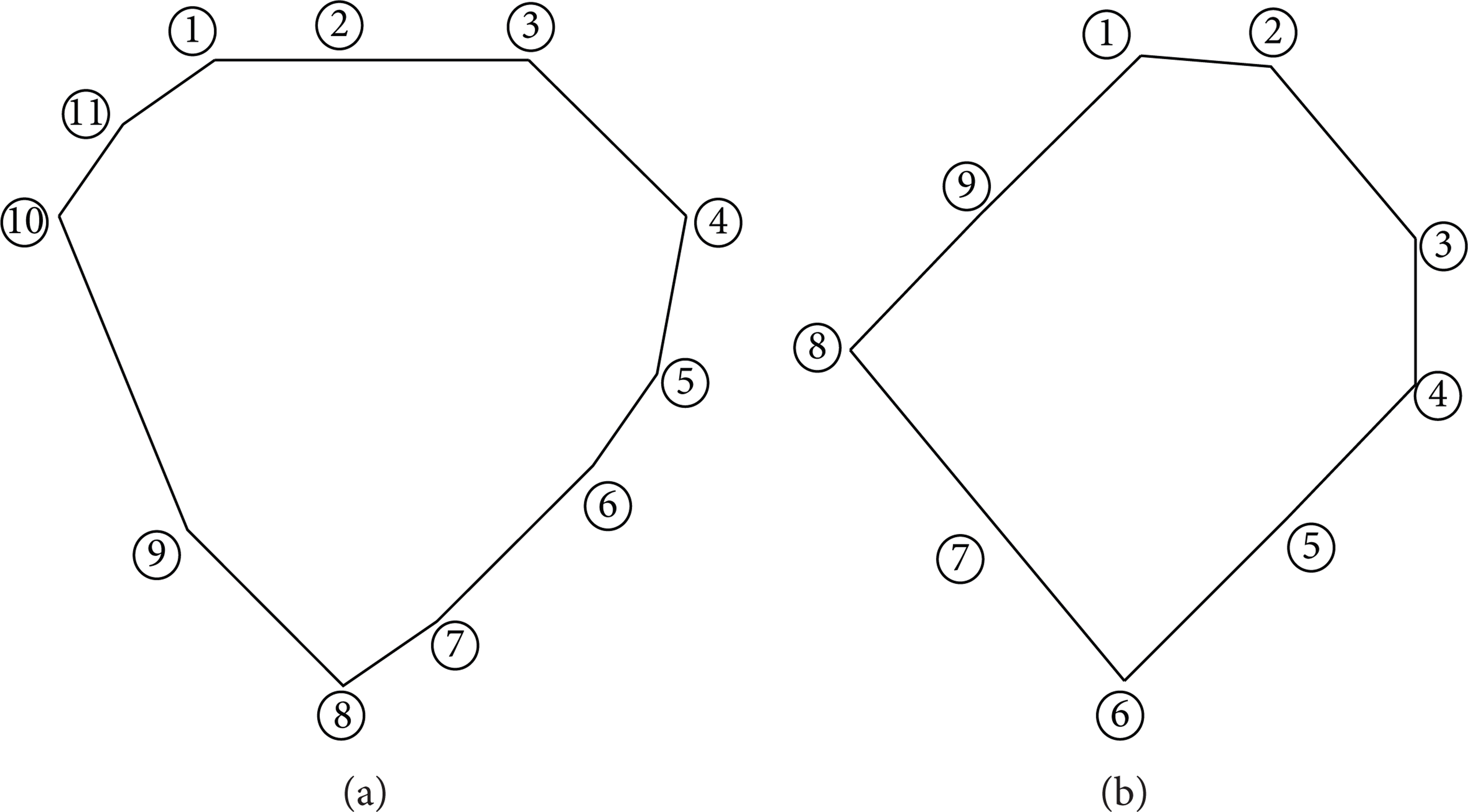
(a) Target area 1 and (b) target area 2 of irregular foldable structures assemblies.

Optimization result of numerical examples for foldable structure using irregular assemblies. (a) Assemblies of foldable structure, foldable structure for the target area 1, and convergence history (
4.4. Realization of Foldable Structure Design
The previous examples show some benchmark problem of the foldable structures and the present optimization algorithm. To show the validity of the present design strategy for real application, we create an arbitrary shaped area by breaking a cap of a plastic product in Figure 21. Then the outline of the hole is scanned and the target area is extracted in Figure 22(a); the key points of the outline can be chosen manually. Here we chose the 2 by 1 foldable structure to cover this break hole. With the present design process, the design of Figure 22(b) can be obtained and its structure is made in Figures 22(c) and 22(d). Due to physical size of a link, we found that the 2 by 1 foldable structure with

Arbitrary target area. (a) A hole creation by using hammer and (b) the created hole.

Optimization result of foldable structure for arbitrary area. (a) The extracted target area, (b) the foldable motions of the 2 by 1 assemblies, (c) the foldable structure for the target area using 2 by 1 assemblies (
5. Conclusions
In this paper, we present new design optimization method of foldable structure. The foldable structure is developed to construct light structure which has sufficient stiffness and strength. However, due to complex deformation mobility of foldable structure, it is difficult to find out appropriate deformation mode satisfying actual requirements. Our recent work focused on the design of deformation mobility of foldable structure which covering arbitrary shaped area by finding appropriate rotational direction of joints and step size angle. To develop new structural optimization method, it is necessary to define appropriate design variables. Through the kinematic analysis of 4RE-linkages, it is found that the deformation mobility can be defined by eight rotational joint and step size angle. Therefore, the mixed design variables which represent the rotational direction of joints as binary design variables and the step size angle as integer design variable are used. Due to two types of design variables, the genetic algorithm treating binary and integer design variables simultaneously is used in this research. The objective function of optimization problem is defined to minimize the sum of distances between target area's reference node point and its closest outer node point of foldable structure. The outer node points of foldable structure are found based on Delaunay triangulation. The usefulness of developed optimization method is verified by successfully designing four kinds of foldable structures covering arbitrary shaped area.
Conflict of Interests
The authors declare that there is no conflict of interests regarding the publication of this paper.
Footnotes
Acknowledgment
This research was supported by the EDISON Program through the National Research Foundation of Korea (NRF) funded by the Ministry of Science, ICT & Future Planning (no. NRF-2014M3C1A6038801).