
Abstract
Underwater sensor networks (USNs) can be used for several types of commercial and noncommercial applications. However, some constraints resulting from the nature of aquatic environments severely limit their use. Due to constraints such as large propagation latency, low-bandwidth capacity, and short-distance communications, a large number of USN nodes are deployed to provide reliability in most applications. In this study, an unattended deployment approach based on the use of an autonomous boat group is proposed. A map of the deployment zone and optimal locations of USN nodes are fed into the onboard computers of the boat group. After processing these data and determining paths to be followed, the boat group deploys sensor nodes at predetermined locations. During the deployment, the boat group is controlled by an artificial neural network- (ANN-) based control system for reducing path errors. A set of performance evaluations is given to prove efficiency of the proposed control system. Performance results show that the boat group can successfully follow a predefined path set and deploy USN nodes. The tradeoffs between energy consumptions, end-to-end delay, and number of hops between underwater relay nodes of energy-efficient USN are also examined. The results indicate that increasing the number of hops reduces the total energy consumption and the end-to-end delay.
1. Introduction
Most of the Earth's surface is covered by water. Sensing and monitoring of aquatic environments are used in several potential applications including oceanographic data collection for fish and mussels growth observation, pollution detection, oil monitoring, seismic and volcanic prediction, coastal surveillance, and different objectives such as exploration, protection, and commercial exploitation [1]. A low-cost approach for all these applications is the use of underwater sensor networks (USNs). In USNs, nodes can be equipped with sensors for the measurement of different parameters such as depth, conductivity, oxygen, pH, turbidity, temperature, and salinity. In USNs, the transmission of information can be realized in the form of acoustic, electromagnetic, or optical waves. All the wireless communication techniques, acoustic, optical, and electromagnetic communications, have pros and cons [2].
Due to the nature of aquatic environments, a number of key constraints like the low-bandwidth capacity, large propagation latency, high bit-error rate, and short-distance radio communications must be taken into account [3]. These key constraints call for the deployment of a large number of sensor nodes for a successful USN. Its key advantage, the low attenuation of acoustic waves in water, makes acoustic communication the most widely used technique in USNs. Although the deployment of USNs can be realized using a number of different approaches, it remains a significant challenge due to the inherent difficulties posed by the underwater communication channel. In addition, budget-related constraints, arising from the high cost of each node, may severely limit the number of nodes that can be used. Therefore, the employment of efficient deployment approaches is necessary for the achievement of successful USNs in real applications.
In this study, an autonomous multi-boat-group-assisted deployment approach is proposed. It is based on the use of artificial neural networks (ANNs) for the control of the multiboat group. Before a deployment mission, a map of the deployment zone and optimal locations of USN nodes, provided by the USN deployment module, are fed into the onboard computers of the boats. The boats process the data and determine the paths that they are going to follow in order to deploy the USN nodes at the predetermined optimal locations. As proven by the simulation studies presented in this study, the use of ANNs reduces the path errors considerably compared to the traditional control approaches. We also investigate the tradeoffs between energy consumption, end-to-end delay, and number of hops for the case of USN. Although similar problems were investigated in previous works [4–6], the obtained results are not sufficient for the particular scenario examined in this paper. Numerical results in this study demonstrate the theoretical derivations.
The remainder of the paper is organized as follows. Section 2 presents a detailed literature survey on underwater sensor network deployment approaches. Section 3 presents a novel strategy for the deployment of USNs and gives the results obtained from a set of simulation studies, which were carried out for the evaluation of this approach. Section 4 provides a detailed description for the implementation of an artificial neural network designed to control a multiboat group that is responsible for the deployment of underwater sensor networks, while it also presents an overview of the performance evaluation results. Finally, Section 5 concludes the paper.
2. Related Work
In recent years, USNs (e.g., cf. Figure 1) have considerably drawn attention of the research communities. Although they offer numerous advantages in several different application scenarios, they come with many issues that need to be addressed. Therefore, factors associated with the success or failure regarding the implementation of USNs should be identified and subsequently handled in an appropriate way. As it has been shown by both simulation studies and field tests, one of the most important phases of all the sensor network implementations is the deployment phase which can be realized in an attended or unattended manner [7, 8]. Since USN implementations are much harder than other sensor network implementations and they are associated with several performance related factors, the attended deployment approaches offer considerable advantages over the unattended ones, including cost-effectiveness.
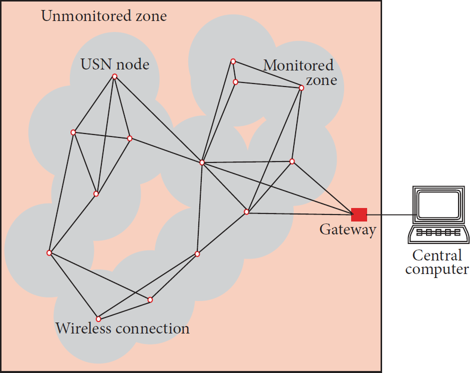
A typical underwater sensor network.
The most important objectives of an efficient USN deployment are (i) to provide full-connectivity coverage and (ii) to optimize the USN lifetime. However, the performance of USNs is greatly limited by the low-bandwidth and high propagation delay of underwater acoustic communications [9, 10]. In this regard, several network-related factors such as the packet reception rate and the delay and throughput, as well as node related factors, such as the transceiver power, the battery, and the CPU power, should be taken into consideration [11]. In [9], Felamban et al. define an optimal node placement strategy for USNs in order to obtain maximum coverage and connectivity with minimum transmission loss. By taking the characteristics of underwater acoustic channels, the authors formulated this problem as a nonlinear programming model. The authors proved that the number of USN nodes required to cover a definite volume depends on the operating frequency. When it is increased, more nodes are required with short internode distances in order to maintain a transmission loss threshold. Due to the abovementioned limitations of USNs, most studies have been focused on specific techniques to enhance USN performance metrics. Ibrahim et al. propose the use of multiple surface-level gateways to improve end-to-end delay and reduce energy consumption by distributing traffic loads [10, 12]. The authors show the significant advantages of their approach.
USN deployments can be realized using different manned or unmanned vehicles including boats and aerial vehicles. Before deployment, the deployment locations of sensor nodes and a map of the deployment site are loaded to the onboard computer of the vehicle or are provided to the human operator. This can be realized online during deployment, too. To realize USN deployments, unmanned autonomous vehicles need an accurate navigation system. In [13], Erckens et al. present a special navigation system that plans an optimal navigation course and efficiently controls an unmanned boat vessel called “Avalon boat” on this course. The navigation system is based on a novel path planner that generates the fastest path to a given destination and is able to avoid both static and dynamic obstacles [13]. While a boat moves on the sea or ocean, it is exposed to several uncontrollable factors that may affect its direction. For unmanned autonomous boats, it is difficult to obtain an accurate model and it requires a lot of sensors to feed a proper controller [14, 15]. A simple boat model which relates the most important variables and concentrates on data that can be provided by low-cost sensors is proposed in [14]. As proven in many field tests, autonomous boat navigation systems cannot easily replace human operators due to uncontrollable factors such as wind and waves [16, 17]. On the other hand, knowledge of sailing experts can be transformed into a fuzzy interference system in order to steer sails and rudder according to weather conditions and target [16].
However, all the aforementioned deployment algorithms are either driven by the deployment cost or performance related factors like the network lifetime. Furthermore, they do not focus on the navigation accuracy of the vehicles that deploy the sensor nodes. Our approach differs from the related studies since it combines a performance-driven deployment scheme with an ANN-based path-following system used for the realization of an USN deployment.
3. Efficient Node Placement for Balanced Energy Consumption and End-to-End Delay of a Multiple-Hop USN
In the following, we present a simulation study to reveal the communication related tradeoffs arising for an acoustic wave USN deployed in a model dam. The USN consists of two entities: the relay nodes and the surface gateway. A sufficient number of nodes are deployed to cover a certain underwater volume, in this case the volume of an orthogonal shallow dam model. The surface of this dam is 3.391 km2, while the depth is 26.3 m. Each node can be deployed in any position, while the location of the gateway node is known. Since the sensor nodes communicate with each other using acoustic links, the path loss is caused by two phenomena: the energy (geometric) spreading and the wave absorption. The energy spreading mainly depends on the transmission range of the acoustic waves [19], while the wave absorption is frequency-dependent; that is, high frequency signals are more vulnerable to absorption loss due to the conversion of acoustic energy to heat. The nodes in the USN are powered by batteries and hence they should be properly placed to reduce path loss and energy consumption. Then, these nodes will maintain their location using various means of location and depth adjustments.
Two-dimensional (2D) shallow-water acoustic communications were considered, since the depth is set to 26.3 m. In this case, the acoustic signals propagate within a cylinder bounded by the surface and the sea floor; that is, cylindrical spreading appears and the signal spreads horizontally due to low depth [20]. We assume that all nodes are equipped with homogenous transceivers and have a cylindrical based communication with a radius of d, where d is assumed to be constant for all nodes. Two nodes are connected if the node interdistance is less than or equal to
Underwater sound propagation is described using the Sonar equations [19]. The source signal level (which is related to the transmission power intensity and hence to the transmission power


Since cylindrical spreading applies for shallow waters, the transmission loss in dB is approximated as [19]


We assume 16-quadrature amplitude modulation (QAM) and orthogonal frequency division multiplexing (OFDM) encoding method. Then, the bit error rate (BER) is derived as [22]

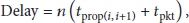
The propagation time in seconds for a distance d in meters is

3.1. USN Simulation Results
In this subsection, we investigate the influence of placing middle nodes to convey information from a source to a destination on the energy consumption and the end-to-end delay. Based on the measurements of medium absorption in shallow water conducted at temperatures between 4°C and 20°C [24] and considering that
Figure 2 demonstrates the total energy consumption (normalized transmission power

The normalized energy consumption of the USN as a function of the number of the hops for different distances between nodes.
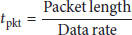
Using (8)–(10), Figure 3 depicts the normalized end-to-end delay in string USN as a function of the number of hops for distances between nodes of 50 m, 100 m, 200 m, and 400 m at depth of 26.3 m. The normalization is obtained by dividing all the values of the delay by its maximum value. One observes that the end-to-end delay almost linearly increases with the augmentation of hops. However, the distance between nodes slightly affects the end-to-end delay. Thus, the number of hops should be carefully determined to compromise energy consumption and end-to-end delay.
The normalized end-to-end delay of the USN as a function of the number of the hops for different distances between nodes.
4. Artificial Neural Network-Based Control of a Multiboat Group
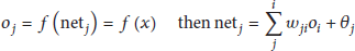
An ANN is essentially a parallel distributed processor made up of simple processing units that has an inherent trend for storing empirical knowledge and making it available for use [27]. Multilayer feed-forward neural networks (NNs) are widely used, while their training is based on the minimization of an error function. Specifically, backpropagation (BP) is a well-known training method that is used in the case of multilayer feed-forward NNs. BP learning uses the gradient descent procedure to determine the connection weights [28].
The multilayer feed-forward NNs consist of one input layer, one or more hidden layers, and one output layer. Each layer is composed of neurons which are connected to the neurons of the neighboring layers. Each connection link is characterized by a weight. The evolution of the online supervised training of multilayer perceptrons has been further raised by the development of the BP algorithm. The following equations summarize the main steps of the BP algorithm. Consider

The optimization method known as Levenberg-Marquardt algorithm [29] was used for the development of the proposed NN. This technique, due to Levenberg [30] and Marquardt [31], is a combination of the following two methods [32, 33]:
the Gauss-Newton's method approaches rapidly near to a global or local minimum but sometimes may deviate; the Gradient descent method certainly approaches through a proper selection of step size parameter but does slowly.
Figures 4 and 5 illustrate the block diagrams and the architecture of the developed ANN.

The block diagram of the proposed ANN. The proposed NN model is used to drive an autonomous multiboat group for following a given path.

The structure of the proposed multilayer NN model was prepared using Neural Network Toolbox of MATLAB [18].
4.1. Performance Evaluation of the Proposed ANN Model
As already mentioned, this study proposes the use of an ANN model for the determination of the path trajectories of multiboat groups used for the deployment of USNs. Lake Buyukcekmece, Istanbul, Turkey, was selected as the application area. It is the major water resource of Istanbul, Turkey, and is located in the Architect Sinan District of Istanbul, on the coast of the Marmara Sea. The lake is 7 kilometers long, 2 kilometers wide, with an average depth of 8.6 meters. It covers an area of 28.47 km2. The Buyukcekmece Dam was built on the sea side of the lake. Besides that, the lake is available for fishing, energy generation, tourism, and irrigation.
In this simulation study, three autonomous boats belonging to a multiboat group in the Lake Buyukcekmece were initially considered at three different static points, while a static target point was also considered. The main objective of this study was that these boats should track a predefined path through which each boat arrives at the target point and then the second and the third boats track the same path to the opposite direction in order to go back to their original positions, while the first boat tracks a different path to go to a new static target point.
The simulated results were obtained using MATLAB Neural Network Toolbox [18] and they were compared to their corresponding actual datasets. Eloquent figures showing both actual and estimated trajectories, marking the coordinates during the progressive movement of the boats, are given for the evaluation of the effectiveness of the proposed method. The data used to develop the NN model were based on a virtual x-y plane coordinate system, where “X” and “Y” were the input variables, while “

Boats paths on the employed virtual x-y plane.
Boat 1 was initially located at the virtual x-y plane position (10, 76), Boat 2 at (24, 50), and Boat 3 at (44, 21). There was a target point which was located at the static position (27, 34). All three boats followed a specific, predefined path to reach the target point. Then, the second and the third ones went back to their original positions, (10, 76) and (44, 21), respectively, while the first one tracked a different path to go to a new target point located at (34, 34). The full dataset used in this study is given in Table 1 and comprises 164 sets of input-output variables values.
Dataset used for the ANN model. The column label “Step” refers to the sequential progressive movement of each boat, while “

The developed ANN model is a 1-input layer, 2 hidden layers (comprising 24 and 22 nodes, resp.), and 1-output layer. As already mentioned, the Levenberg-Marquardt optimization algorithm was used since it presents certain advantages against the simple BP [34]. Table 2 shows the test dataset, while Table 3 shows the corresponding ANN results for the test data. The comparison of the training dataset with the corresponding ANN results for Boat 1, Boat 2, and Boat 3 is given in Figures 7, 8, and 9, respectively. Figure 10 shows a combined view of the training datasets and ANN obtained positions for all three boats.
Dataset for test.

ANNs results.

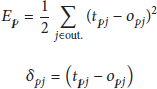
The comparison of the training set and ANN results for Boat 1. Since the ANN has driven the boat very successfully, the ANN results and the dataset coincide. Therefore, it is difficult to locate some symbols in this figure.

The comparison of the training set and ANN results for Boat 2. Basically, overlapping or close symbols indicate that the ANN has successfully driven the boat to the target points in the path.

The comparison of the training set and ANN results for Boat 3. As it can be seen, the proposed ANN has driven the boat successfully except for a few points.

The comparison of the training set and ANN results for all boats. Overlapping points indicate that the ANN has successfully driven the boats to the target points in the path.
Before entering the ANN model, the input dataset was normalized for more reliable results and then rescaled to the original dataset. The activation functions used for the neurons of the proposed ANN model were tangent-sigmoid functions for the 2 hidden layers and linear transfer functions for the output layer. In addition, specific algorithms such as the one proposed in [35] can be implemented in order to speed up the convergence of ANN training phase.
The performance of the NN model and regression between target and NN output are shown in Figures 11 and 12, respectively.

ANN training performance. Epoch is basically one step iteration for all the input dataset in order to train the neural network. In BP algorithm, for each epoch, a different network model with a different set of weights is created. Typically, a large enough value of epoch is chosen to ensure mean squared error converges and overfitting is not observed.

Regression between target and NN output. The regression values measure the correlation between outputs and targets. Overlapping or close points mean a close relationship.
5. Conclusion
In this paper, an unattended deployment approach for underwater sensor networks has been proposed. The proposed approach combines an efficient node placement strategy with an artificial neural network- (ANN-) based control system in order to drive an autonomous multiboat for deploying underwater sensor network (USN) nodes. The node placement strategy provides balanced energy consumption and reduces end-to-end delay of the USN nodes.
Performance results in this paper have shown that the proposed ANN-based control system can drive an autonomous multiboat group to enable them to follow a predefined path set successfully in order to deploy USN nodes. In addition, a set of performance evaluations has been performed to show the efficiency of the proposed node placement strategy. The tradeoffs between energy consumption, end-to-end delay, and number of hops in string network have been also investigated. The results revealed that increasing the hops in the acoustic link almost linearly increases end-to-end delay but reduces the total network energy consumption. These results can be used to determine the number of hops that satisfy the energy consumption and end-to-end delay requirements.
Footnotes
Conflict of Interests
The authors declare that there is no conflict of interests regarding the publication of this paper.
Acknowledgment
This research has been supported by Yildiz Technical University Scientific Research Projects Coordination Department, Project no. 2013-04-04-KAP02.