
Abstract
Recently, indoor location-aware applications that provide interactive capability with the surrounding physical environment are increasingly in demand. These applications include mobile asset management, indoor navigation, and location-based reservation systems. In many cases, these services require multiple and dynamic collaborations over a large number of service subscribers with a deterministic, fast response time. However, many studies still function primarily on client/server-based centralized architectures that are inefficient in supporting complex collaboration, due to their static organization and unpredictable network congestion. To address this problem, we propose a middleware architecture named Dynamic Reconfigurable Agent Space (DRAS), based on a collaboration of service agents that can be distributed over the requested service area. A service application can dynamically modify a service area according to the request of the service subscribers under the DRAS. To demonstrate the feasibility and performance of the DRAS, we evaluated the elapsed time for dynamic reconfiguration of the service area. Also, two general collaboration scenarios in indoor location-aware applications called voting and tracking were evaluated in the simulation and in a real environment. The evaluation shows that the proposed middleware is suitable for indoor location-aware applications that require a large number of mobile nodes and complex collaboration by the effective distribution of network traffic and processing around the service agents.
1. Introduction
Recently, ubiquitous sensor network technology has enabled complex associations between humans and physical objects or physical and virtual environments. Interaction with the surrounding physical environment and personalized services is increasingly in demand for applications such as mobile asset management [1–3], indoor navigation [4–7], and location-based reservation [8] systems. However, these services are still based on centralized client/server-based architectures that are inefficient in supporting multiple complex collaborations that require real-time responses over a large number of service subscribers. These centralized architectures are insufficient because of their static organization and heavy resource surge. For example, messages generated in current services need to be delivered to the centralized server using multihop communication, therefore causing traffic bottlenecks on the paths to the server that can potentially stop all functioning services. To solve this problem, this paper proposes a Dynamic Reconfigurable Agent Space (DRAS), a special middleware architecture based on service agents that can be distributed over the space of a service area while facilitating greater and more efficient collaboration among services and service subscribers. The service agents can dynamically expand and contract their service areas according to the location of service subscribers under the DRAS. This approach can guarantee better collaboration performance with a large number of service subscribers by ensuring the effective distribution of network traffic around the service area.
The DRAS is designed for an indoor wireless sensor network environment consisting of stationary and mobile nodes. In this paper, it is assumed that mobile nodes are characterized by low-speed operations and ultralow power consumption and can be attached to physical mobile objects in the form of small tags. We will call these devices mobile nodes and regard them as service subscribers. Stationary nodes are also characterized by high-speed operations and low power consumption and the ability to be attached to ceilings or walls of unit spaces. They are intended to function as location references and communication access for mobile nodes (see Section 2.1 and Figure 1). The expansion and contraction of service areas are enabled by dynamic generation and destruction of service agents according to the request of mobile nodes. With the dynamic reconfiguration of service areas, the effective distribution of network traffic and service processing amidst numerous mobile nodes is guaranteed.
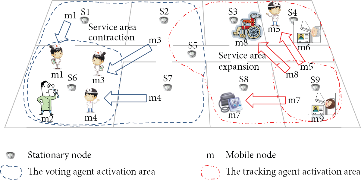
Conceptual overview of U-Hospital services with dynamic reconfiguration of service area.
The main contributions of this paper are as follows.
Service agents can be dynamically distributed over the service area on the demands of service subscribers (mobile nodes). This approach can provide fast service responses by distributing network traffic and service processing. Further, it can be used as a realistic solution for indoor location-aware applications that require a large number of mobile nodes and complex collaborations. We present two general collaboration services, namely, voting and tracking, that operate under the DRAS. These can be used as practical location-aware services or reference models that are needed to track, collect, and confirm the opinions of service customers. The DRAS was designed and implemented using Erlang [9]. Due to the Erlang-based implementation, the implementation complexity can be reduced significantly despite complex coupling among agents. The performance of the DRAS with the aforementioned services was evaluated. The elapsed time for changing the service coverage was measured in a real environment. In addition, this study measured the elapsed time of the voting service both in the simulation and real environment and the tracking service in the simulation. Also, the performance between the centralized architecture and the DRAS was observed.
The contents of this paper are organized in the following manner. Section 2 examines the domain description and related research. Section 3 explains the design considerations for the DRAS. Section 4 describes the conceptual design of the DRAS, and Section 5 explains the operating principles of the DRAS. Section 6 describes the implementation of the DRAS architecture, and Section 7 presents a test-bed implementation and performance evaluation. Finally, Section 8 summarizes the work and draws conclusions.
2. Domain Description and Related Research
2.1. Domain Description
In general, a location-aware application means a service that can dynamically adapt its characteristics and functions to the current location of service subscribers that have free mobility. The application can provide many advantages in a building environment that has a complex indoor structure (e.g., irregular space shapes, inner rooms, etc.) and lots of opportunities for collaboration between people and objects. However, there is the traffic bottleneck problem with server-side approaches [10–12] and the multihop problem (e.g., broadcast storm, packet replication, and routing table overflow) with mobile agents approaches in wireless sensor networks (WSN) [13–15].
In this section, to help explain the proposed concept, we introduce a service environment named U-Hospital. This service environment best illustrates service scenarios that require complex collaboration and real-time responses among a large number of service subscribers in indoor location-aware applications (e.g., mobile asset management [1–3], indoor navigation [4–7], and location-based reservation [8] systems). A U-Hospital has some distinctive features as follows.
First, the whole environment can be divided into small spaces like rooms or floors. Such spaces are called unit spaces and are the basic units for assessing location awareness. Even though this approach does not provide accurate location information such as x-y coordinates, it does suggest enough location information (e.g., cardiac center-501, vascular center-613, etc.) for many U-Hospital services without complex computation on the mobile node side.
Second, communication devices are divided into stationary nodes and mobile nodes according to their functionality and features. A node means a communication device that is implemented in hardware. A mobile node can be attached to a person or a medical device in the form of a small tag since it has very limited hardware (e.g., 8-bit MCU, 4 K SRAM, and coin battery) and communication functionality. Unlike RFID tags, however, mobile nodes can communicate bidirectionally. We will regard a mobile node as a service subscriber. There can be a large number of mobile nodes in a service environment. A stationary node can be installed in the ceiling or walls in every unit space to provide location reference functionality and communication infrastructure for mobile nodes. A stationary node has a wired network for communication between stationary nodes and a wireless (sensor) network for communication between mobile nodes.
Third, we limit the communication between stationary and mobile nodes to a single hop. This approach can help to minimize the notorious network congestion and delay problems that take the forms of broadcast storms, packet replication, and routing table overflows in multihop ad hoc sensor networks. This approach can also maximize the possibility of supporting deterministic communication over a large number of mobile nodes. This approach was already used in our previous study [12] and is one of the key ideas in opportunistic networking. An opportunistic network provides at least the following two functionalities: node discovery and one-hop message exchange [16]. In a U-Hospital, these two functions are provided by collaboration between a stationary node and a mobile node and also between two or more stationary nodes.
Fourth, a service is provided by distributed agents in the stationary nodes. An agent means a software program that resides in the stationary nodes to perform its tasks automatically and continuously. In this paper, an agent and a service agent have the same meaning and will be used interchangeably. Generally, service requests are processed by the agent in the same location as the service subscribers. Figure 1 shows a tracking service (will be explained in the last paragraph) for a wheelchair (mobile node m9) that is processed, not by the central server but by the agents in the S9 and S3 stationary nodes.
Fifth, a service area can be dynamically reconfigured without stopping or recreating the service. For example, with the dynamic approach, when a patient in an intensive care unit is ready to move to a normal ward, services that support the patient could just automatically modify their service areas without manual adjustment of those services. This feature has significant advantages compared to previous, static approach [12], which cannot change service areas. Our dynamic approach can support optimized resource requests and collections. For example, if a service area is fixed and the service needs to be provided to mobile nodes that do not know where to go, a service should cover all the unit spaces in the building. When a service agent needs a remote context, the agent needs to send the request message to all agents in the building environment. However, if the service area can be dynamically reconfigured, a service agent can send the request message directly to the clustered agents in one particular service area. In addition, the static approach is too inefficient in resource management because an unused agent needs to be assigned manually, and, when it is not in use, it still consumes valuable resources (power, memory, etc.) and takes up time being managed manually by human resources. If, however, the agent is being managed dynamically, it can be automatically put into sleep mode or turned off completely to reduce power consumption.
Voting and tracking are essential elements of a mechanism design for fully distributed and location-aware systems [17–20]. Many services, such as mobile asset management, indoor navigation, and location-based reservation systems in location-aware applications, can be explained easily by two services: voting and tracking. Given this background, we implemented the two foundation services under the DRAS to provide a clear understanding.
As shown in Figure 1, in a U-Hospital, any stationary node can activate any service agent and expand its service area by creating a clone agent (meaning a new instance of the same service agent) to handle location-based service requests from mobile nodes. In this way all mobile nodes can freely move anywhere without service restrictions. Of course, if the mobile nodes’ locations are reduced, then the service area also shrinks. The voting service can be used for continuous monitoring and status determination of patients by collecting and analyzing sensor values from a variety of medical devices such as sphygmomanometers and electrocardiographs. The current status of the patient can be recognized by a majority rule of sensor values, which can reduce false alarms. Basically, the voting service can be defined as follows: the monitoring service + data processing + decision making. Through voting services, we can show how processing and networking can be divided in the given service area under the DRAS. The tracking service can be used for real-time tracking of medical equipment. Tracking is the application that our previous study [12] was mainly focusing on in indoor location-aware services. It is important to provide the tracking of large-scale mobile nodes and to deal with frequent moves of mobile nodes. Through the tracking service, we can show how the information of mobile node is managed in Peer-to-Peer(P2P) manner under the DRAS.
2.2. Related Research
Recently, opportunistic computing and networking [21–23] have become important concepts in the service computing area, driven by the rapid growth of mobile computing and ad hoc networks. The main concept of opportunistic computing is as follows: “when two devices come into contact, it provides a great opportunity to match services to resources, exchange information, cyberforage, execute tasks remotely, and forward messages” [21]. This definition makes opportunistic computing highly suitable for location-based ubiquitous service applications because the communication and computing are processed by means of a social relationship and collaboration among communication nodes. An opportunistic network provides at least the following functionalities: node discovery and one-hop message exchange. In other words, in an opportunistic network, there is the opportunity for nodes to recognize and communicate with other nodes in close physical proximity [16]. Therefore, the proposed middleware architecture is introduced that can create communication opportunities and provide exchange services between stationary nodes and mobile nodes that approach each other based on the described concepts.
uMATI [12] is our previous WSN and centralized server-based approach for indoor location-aware applications. It provides a three-tier architecture for mobile asset management services applicable to warehouses, hospitals, and so forth. The main issues in this paper were to determine how one can maximize the reactivity identifying the location of mobile nodes in both the server-side and mobile itself and how to solve the problems supporting the numerous mobile nodes in real time. To prevent traffic overflow due to the concentration of excessive mobile nodes into a single location, we added a specially designed stationary node, called a virtual sink (VS) node, supporting one-hop communication between mobile nodes, stationary nodes, and service middleware. With this approach, we achieved better performance than the legacy WSN approach like Zigbee. However, due to traffic bottlenecks on the server-side, complex collaborations were difficult to support.
Mobile agent reactive spaces (MARS) [11] is a coordination infrastructure for mobile services (M-services) that depends on a user's location, whether physical (in space) or logical (within a specific distributed group/application). This paper presents a general service scenario, basic background concept, and definition-related M-services. It also details the modeling framework based on local and active service contexts and discusses the impact of the framework on application design. MARS provides a modular and flexible approach to the design of distributed applications exploiting location-dependent M-services. However, it does not provide any information on an environment that has a large number of mobile nodes and complex collaborations.
AlarmNet [10] has proposed a network and software architecture for pervasive adaptive healthcare services. The network consists of a mobile body network, emplaced sensors, and a back-end network. The mobile body network consists of an electrocardiograph, pulse oxymeter, accelerometer, and other sensors. The emplaced sensors include temperature, dust, light, and motion sensors and are installed in living spaces. The back-end network analyzes the collected sensor values and generates feedback. Even though the whole service network is divided into multiple layers similarly to the approach proposed here, service manipulations are not performed in the emplaced sensors but in a centralized server/database in the back-end network.
TeenyLIME [13, 14] is a tuplespace-based application middleware that is designed for a WSN environment without base stations. In this paper, a new tuplespace implementation that can provide event-driven asynchronous reads/writes among mobile nodes on top of TinyOS has been provided. In addition, this paper presents several example services including multihop communication, remote function invocation, and node and service discovery. The main advantage of this middleware is its ability to support fully distributed services and easily configurable networks. However, it is difficult to provide real-time responses in such services, especially when many mobile nodes are using them.
Agilla [15] is a mobile-agent-based service middleware for a WSN environment. In this middleware, an agent can be moved or copied among mobile nodes without losing its internal contexts. Communication among agents is accomplished by the abstract functions of a tuplespace and an internal neighbor list. Agilla is especially suitable for handling situations in which local decisions would significantly reduce the amount of data to be transmitted wirelessly. A service agent can be implemented in a stack-based instruction set architecture for supporting resource-constrained mobile nodes. However, creation and control of the services are very difficult in this environment because of its assembly-line programming model. We think that this approach is suitable for an emergency service with a small number of mobile nodes but not for a common service with a large number of mobile nodes.
Many studies, including middleware approaches [24–27] and WSN protocols [28–30], have been proposed for indoor location-aware applications. However, these studies are also based on multihop communications and need to deal with complex calculations on the mobile-node side. Therefore, it is difficult to adapt their proposals to provide the services needed for real-time response with a large number of mobile nodes or for network stability.
3. Design Considerations for the DRAS
3.1. Supporting Location-Based Services Especially with User, Time, and Location Contexts
A service under the DRAS is highly related to various contexts [31], especially the service user, current time, and service location. This means that the service decisions or actions would vary if the context was changed. To support this seamlessly, the DRAS should provide a common functionality to access and share these contexts among the service agents. The service agents should be able to detect the context changes automatically or periodically.
3.2. A Fully Distributed Service Network Providing Autonomous Creation, Expansion, and Destruction of Service Clusters
A service cluster is a set of service agents that provide the same service. The DRAS should provide dynamic creation, expansion, and destruction of service agents as needed. A service can achieve real-time responses and increased stability by following distributed service agents around the set of stationary nodes with which the mobile nodes want to communicate. These functions will be accomplished by implicit or explicit requests made by mobile nodes.
3.3. Collaborative Environment between Mobile and Stationary Nodes
The hardware specifications of mobile nodes can vary greatly depending on service requirements. However, in general, they have a cheap, low-speed MCU, a limited amount of memory, low-speed communication, and a small battery. Thus, to process complex and difficult jobs in the services, collaboration among mobile and stationary nodes is essential. Generally, stationary nodes process multiple jobs coming from various mobile nodes because of their greater processing efficiency, but the reverse could also occur.
3.4. Network Unawareness
Service customers should receive the services by making use of all available network resources without dealing with the complexities of network configuration. Transparency among communication protocols should be provided between mobile and stationary nodes. Moreover, service disruptions should be minimized except when all methods of communication have disappeared.
4. Conceptual Design of the DRAS
4.1. Overview of the DRAS
The DRAS can associate mobile nodes with the agents and destroy the agents freely according to the needs of the service customer. In the DRAS, a service can communicate with mobile nodes regardless of the nodes’ physical locations and the communication protocols being used. A virtual social network could be generated among mobile nodes (eventually the customers) participating in a service and large quantities of information could be generated among the customers. A service is provided by service agents that are distributed according to the stationary nodes in the form of processes and connected to each other by P2P connections. Unlike server-based centralized architecture, network traffic and service processing are distributed naturally to multiple stationary nodes. Collaborations with the service agents are a key consideration in the DRAS. The DRAS uses only one-hop ad hoc communication to communicate between stationary nodes and mobile nodes for efficient operation, so there is no need to consider complex management of a routing table on the mobile nodes side.
In the DRAS information model, a service agent S is defined as a tuple S = (name, self-introduction, M, N, C, and H), where a name is a unique name of a service, self-introduction is a self-descriptive string of a service, M is a set of addresses of mobile nodes that subscribe to the service, N is a set of addresses of stationary nodes where the service is distributed, C is a set of service contexts, and H is a service handler (name of the compiled service code). A context is a pair
A message Msg is defined as a tuple Msg = (srvname, from_addr, to_addr, command, Data, Opt, and msgref), where srvname is the target service name, from_addr is the address of the message sender, to_addr is the address of the target, command is a command name to execute, Data is a list of parameters for the command, Opt is a list of service options, and msgref is a reference ID for the message. For instance, we can represent a message “mobile node 100 will move to room-502 from room-501” in the tracking service as

4.2. Network Architecture Supporting Distributed Collaboration in the DRAS
To support real-time service responses with a large number of mobile nodes, the nodes have been divided into stationary nodes and mobile nodes. Moreover, the network was divided into a backbone and multiple service regions for one-hop ad hoc communication. Figure 2 shows the proposed network architecture of the DRAS. The stationary tier is composed of stationary nodes (marked S in Figure 2), which manage unit spaces, and a backbone network that connects the stationary nodes. The mobile tier is composed of mobile nodes (marked M in Figure 2), which can be attached to objects or to service customers, and the regions serving the one-hop ad hoc network. Communication among stationary nodes is performed in the P2P style rather than by the traditional client/server style. A service request coming from a mobile node can be handled by a service agent running in a stationary node. Otherwise, it will be served by collaboration among agents distributed in several stationary nodes (drawn as a service cluster in Figure 2).

Two-tier network architecture of the DRAS.
It is assumed here that the stationary nodes have plenty of computing capability and a permanent power supply. To increase the lifetime of mobile nodes, we have to carefully consider the power consumption of the mobile nodes. To efficiently communicate between stationary and mobile nodes, we used the LIDx/LAMD one-hop ad hoc protocol that was proposed in previous studies [32, 33] and will be explained in the following section. This protocol enables one-hop-based location determination and asynchronous message delivery between stationary and mobile nodes based on IEEE 802.15.4.
4.3. LIDx and LAMD for Location Determination and Message Delivery among Service Agents and Customers
LIDx and LAMD [32, 33] are protocol sets that were designed for asynchronous communication between stationary nodes, mobile nodes, and a centralized server. LIDx is an abbreviation for “Location-ID Exchange protocol,” which is used for location awareness between stationary and mobile nodes. The basic operation scheme of LIDx is as follows. A mobile node broadcasts location-awareness packets to stationary nodes to determine its current location. When stationary nodes around the mobile node receive these packets, they will check the link quality indicator (LQI) of the packet received. Then each stationary node sends a packet to the mobile node including the received LQI value. The mobile node gathers packets from stationary nodes and analyzes the LQI values in the packets. Finally, the current location of the mobile node is determined by selecting the stationary node that sent the packet with the highest LQI value. The mobile node then sends the result to the stationary node. Even though this method cannot provide x-y coordinates like a GPS, it can simply and easily suggest an approximate location, which is sufficient for most indoor applications. It is suitable for use in low-powered mobile nodes to provide location awareness for opportunistic services. LAMD is an abbreviation of “LIDx-based Asynchronous Message Delivery,” which is used for exchanging asynchronous messages among mobile nodes. The message-exchange sequence is a multistep process. When a source mobile node wants to send a message to a particular destination mobile node, it first sends a message to a stationary node. The stationary node in turn sends this message to the server. It is assumed that the location information of mobile nodes is continuously collected by a server so that the message can be routed to the stationary node closest to the target mobile node. Finally, the message will be sent to the destination mobile node.
After some modifications to fit a distributed environment, we used them as the primitive location determination and message delivery protocols between mobile nodes and stationary nodes to implement the DRAS. For LIDx, the location information of mobile nodes is no longer managed by a centralized server. Instead, it is distributed in the stationary nodes following where the mobile nodes exist. For LAMD, the message-exchange sequence has changed. When a stationary node receives a message, the stationary node first checks whether or not the target is in the current location by searching the local context. If not, it will search for a remote context and transfer the message to the proper stationary node where the target mobile node exists.
5. Operating Principles of the DRAS
All services in the DRAS are processed by collaboration among distributed service agents, and the collaboration is done asynchronously by message passing. Figure 3 shows the general collaboration concept with local and remote contexts under the DRAS. To collaborate with distributed service agents, a service agent should send its request to target service agents and, if needed, collect results from the service agents. It can be simply represented by two interfaces:


General collaboration concept of the DRAS.
where cmd is a command for collaboration, TargetAgents is a set of addresses of the target stationary nodes that have remote contexts, R is a set of information to be collected including what and where, Opt is a set of options, and L is a set of collected contexts. With combinations of two interfaces, we can achieve various collaborations. A service should implement two interfaces according to its requirements. It should be noted that collaboration among the service agents is a fairly expensive operation. Therefore, simple and common service requests from mobile nodes should be processed as much as possible based on local context.
Another point to consider is that internal blocking functions should be eliminated or used with extreme caution when an agent requests a remote context in a message loop (cf. Remote Procedure Call). Blocking functions prevent an agent from processing messages in its message queue before receiving the requested remote context and, therefore, can create a deadlock problem when remote contexts are heavily related to each other. One possible solution to get rid of the deadlock problem is to make delegate processes. A service agent can invoke a new process (or an agent) that deals with the blocking function and will get the returned value asynchronously (an example is shown in “gathering process” in Section 6.5). In this way, a service agent can keep its message loop working even though the blocking function is not responding. For instance, in general, the collection function is implemented using a delegate process.
A service can dynamically modify its service coverage by changing service agents. Each of the service agents is managed by a process in the DRAS. A service agent can exist in one of the following states: creation, expansion, processing, contraction, and destruction. We call the first element in N the “main agent” and the remainder “colleague agents” (see Section 4.1). For the sake of easy implementation, some critical synchronization sequences among service agents are managed by the main agent at the time of writing.
First of all, a service cluster should be created to provide the service such as U-Hospital to service subscribers. A mobile node which has information about the required service can create the service cluster. Figure 4(a) shows the service creation step. Figure 4(a)-

Service creation and coverage expansion process in the DRAS.
To participate in a service, a mobile node should be within radio range of the service cluster. When a mobile node is not in range, the service will simply not be provided. However, if the mobile node wants to expand the physical service area because service subscribers are increasing or the current location of the mobile node needs to be participated in the service cluster, the mobile node will request an expansion of the range by creating a service agent in the stationary node of the current location. Figure 4(b) shows the service coverage expansion step. In Figure 4(b)-
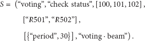
On the contrary, the physical coverage of the service cluster needs to be contracted when the service subscribers are decreasing or the service agent of the current location in the cluster has no more subscribers. Figure 5(a) shows the steps in service coverage contraction. When a service agent has not received any messages from any mobile nodes for a predefined period of time, the service agent determines that the current location no more needs to be participated in the service cluster. So, the service agent will quit the service cluster automatically. Figure 5(a)-
Service coverage contraction and destruction process in the DRAS.
Finally, a service should be eliminated when it is no more required. Figure 5(b) shows the steps in service destruction, which are similar to a service coverage contraction. Figure 5(b)-
Service collaboration between other clustering services is also required. In this paper, basically, a service cluster is expected to run its assignment without collaboration among service clusters. However service clusters can share their information easily under the DRAS and a service cluster is encouraged to collaborate with other service clusters. Even though a general collaboration process among service clusters is not proposed at the time of writing, it will increase usability of emerging WSN services.
6. Implementation of the DRAS Architecture
6.1. Overview of the DRAS Middleware Implementation
Figure 6 shows the DRAS middleware architecture. The proposed middleware has three main managers: a collaboration manager, a repository manager, and a communication manager. The collaboration manager takes charge of the management of collaboration agents including the lifecycles of service agents. The repository manager handles global service contexts, including the location of mobile nodes and environmental data. The communication manager deals with communication between stationary and mobile nodes. Each manager contains several processes such as message loops, worker processes, and controllers. Message passing is the only way to communicate among processes in this middleware architecture. This means that communication transparency between local and remote processes can be provided throughout the services and that the influence on other processes of the sudden failure of one process can be minimized, even though the response time of the services would be increased by message-handling overhead.

The DRAS middleware architecture.
Table 1 shows the overall footprints of the DRAS source codes. This middleware has been implemented with C++ and Erlang [9]. Erlang is a programming language that supports fast process creation, control of large numbers of processes, and fast communication among processes for distributed systems. In the DRAS, an agent is implemented as an Erlang process, which is a kind of lightweight process that can be provided and scheduled in an Erlang virtual machine. A stationary node can have as many agents as possible if resources are available. An Erlang process is similar to an operating system process, but its creation, deletion, and communication performances are very high. Erlang also has a higher statement ratio than C++ with a functional programming feature. However, hardware control is very limited. Therefore, the collaboration manager and the repository manager have been implemented in Erlang because they need to control and communicate with many processes. The communication manager has been implemented mainly in C++ but partly in Erlang, because it controls multiple communication protocols for mobile nodes, including hardware access. All messages based on ad hoc communication protocols will be converted to TCP/IP-based messages in the communication manager, and TCP/IP-based messages will be converted before transmission to the ad hoc protocol depending on the target mobile node. Service applications can be implemented freely in C++ or Erlang, but Erlang is the better choice for complex applications. It is assumed that binaries for service applications have been installed in entire stationary nodes before the service is executed. In the future, they will be automatically installed.
Footprints of the source codes.

6.2. Collaboration Manager
The collaboration manager takes charge of the management of collaboration agents including the lifecycles of service agents. In addition, it acts as a name server to process service coverage expansion requests from mobile nodes. Algorithm 1 shows a portion of the source code that was written in Erlang for the collaboration manager. “Newservice” is a function that can create a service cluster by requesting the creation of service agents over stationary nodes. For this, a common service context is used and is defined as “#context” including a service name, a session ID, and service agent information. After the request, the “gather” function collects acknowledgement messages from the stationary nodes. Each of these messages includes the process ID of the agents and the result of the agent creation process. If all agents have been created successfully, the service context is transferred to the service agents. After these steps are completed, the service cluster is ready to start. To provide a naming service, the collaboration manager simply saves the service name and process ID as a tuple. It will be automatically updated when its service cluster is created or deleted.
newservice(#context{service=Service, sessionID=SessionID, agents=Agents}=C) -> L = Agents, %% spawn services among required nodes map(fun(I) -> {oppservice, I} ! {self(), C} end, L), % request func. Gather = gather(L, SessionID), % collect func. %% convert node information to pid AgentP = map(fun(From)-> {_, Pid, _, _, _} = lists:keyfind(From, 1, Gather), Pid end, Agents), %% transmit context to all agents ok.
6.3. Repository Manager
The repository manager is a kind of in-memory database for administering global contexts such as the location information of mobile nodes and environmental data. Generally, for efficiency, service-specific contexts are managed in each service agent. The repository manager uses Mnesia, which is a built-in database management system for Erlang. The database can save a wide range of context types. For example, simple values like temperature and complex data structures can both be stored. Algorithm 2 shows a portion of the main message loop in the repository manager, which updates the location information of mobile nodes. When an LIDx message is delivered from the communication manager, it will be saved into the “loc” table as a record with its arrival time. When a mobile node moves away from this location, the stationary node will no longer be able to receive LIDx messages from the mobile node, and therefore the message arrival time will not be updated. The “garbage_collector” function periodically removes those records that have not been updated for a predefined period of time. The services that want to use the location information should check the message arrival time to prevent annoying duplication problems.
(i) define(DBMODE, 1) %% raw (no transaction) mode (ii) define(PERIOD, 30000) %% 30000 ms repository_msgloop() -> receive %% update mobile-node location information {_From, #loc{userID=_UserID, locID=_LocID, locSubID=_LocSubID, curTime=_CurTime}=R} -> row_write(?DBMODE, R), memorydb_msgloop(); %% garbage collection {_From, garbagetime} -> garbage_collector(), memorydb_msgloop(); end. garbage_collector() -> CurTime = calendar:datetime_to_gregorian_seconds(calendar:universal_time()), %% In SQL, SELECT loc.userID FROM loc WHERE %% CurTime-loc.curTime > ?PERIOD Del = do(qlc:q( if length(Del) > 0 -> true -> ok end.
6.4. Communication Manager
The communication protocols for mobile nodes can vary depending on the characteristics of their services and the limitations of the mobile nodes. To support various ad hoc protocols, a communication manager is implemented in C++ and Erlang. In the C++ part, protocol-specific messages are first converted to TCP/IP-based messages. In the Erlang part, the TCP/IP-based messages are converted to Erlang messages for easy manipulation by Erlang processes. Because of this two-step conversion, service agents do not need to concern themselves with protocols of mobile nodes. In other words, transparent communication can be provided among service agents and mobile nodes. Algorithm 3 shows a part of the header source code of the gateway class written in C++ for the communication manager. The class contains several class objects and functions to convert mobile messages into TCP/IP messages and vice versa.
class Gateway: public QObject { private: static const int HeaderSize = 4; QSerialPort *serialPort; TcpSocket *tcpSocket; TcpServer *tcpServer; QTimer *timer; void makeSerialBlock(); void makeEthernetBlock(); public: void doBeacon(); void writetoMobile (QByteArray & arr); void writetoStationary (QByteArray & arr); void onDataReceivedFromMobile(); void onDataReceivedFromStationary(); void timeouted(); };
6.5. Service Agent-Customer Collaboration Scenarios: Voting and Tracking
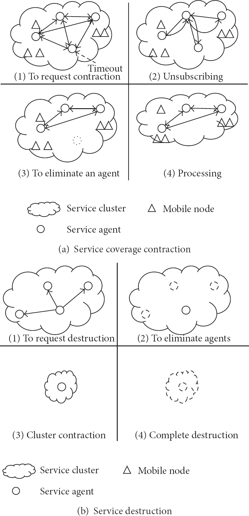
The voting service is a kind of collaboration service that can collect and confirm the opinions of service users. The collected information can be an important resource to decide future actions for a service. In particular, this scenario is well suited for collaborative indoor navigation [4–7] or for self-organizing systems [34–36]. Figure 7 shows a sequence diagram of the voting service. First, a start message will be sent to the service agent when the voting service is needed
A collaboration sequence diagram among agents of the voting service.
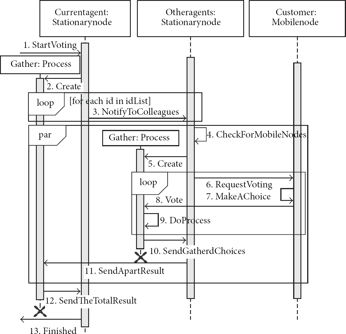
The tracking service is designed to track multiple mobile nodes in real time. It assumes that each of the mobile nodes moves along a permitted trajectory. If a mobile node moves to a forbidden location or visits locations in the wrong order, a warning message will be sent to the mobile node and to a service administrator to prevent unauthorized intrusion. To implement this service, we will use a simple data token that includes information on the mobile node and an ordered list of permitted locations. At the beginning of a service, the main service agent creates one token per mobile node. After that, the tokens will be managed by the distributed service agents. This scenario is well suited to various mobile asset management environments [1–3]. Figure 8 shows a sequence diagram of the tracking service. First, when a mobile node sends its current location to a stationary node using LIDx
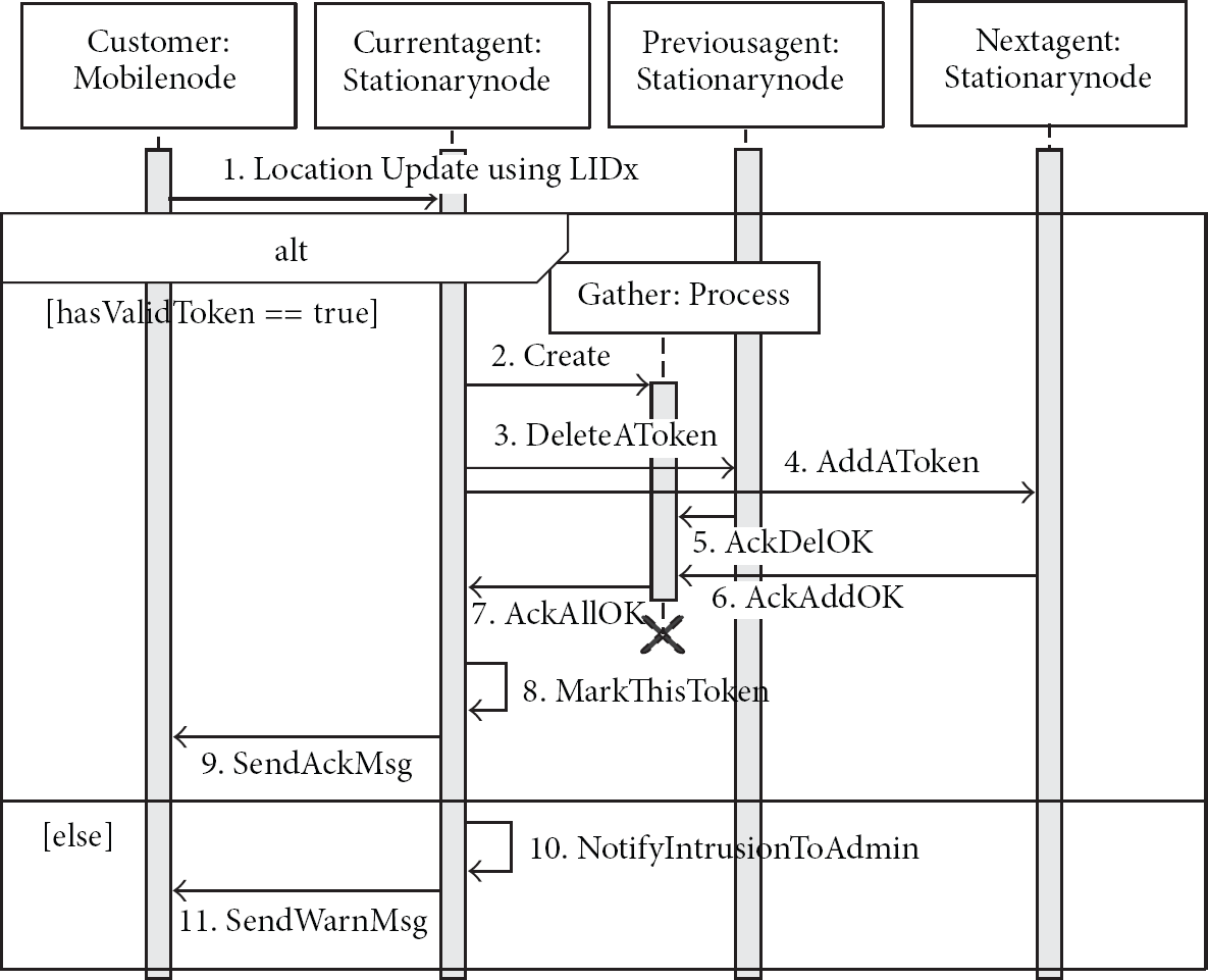
A collaboration sequence diagram among agents for the tracking service.
7. Test-Bed and Performance Evaluation
To verify the proposed middleware and evaluate its performance, we set up a test-bed consisting of 10 stationary nodes, 50 mobile nodes, one PC, and one Ethernet hub, as shown in Figure 9. The mobile node has an 8-bit MCU embedded with an IEEE 802.15.4 transceiver, 8 KB SRAM, and 256 KB flash memory. The stationary node has an Arm Cortex A8 MCU with 512 MB SDRAM and an IEEE 802.15.4 transceiver for communication with mobile nodes. The transceiver is same as a mobile node. To evaluate performance on a large number of mobile nodes, we also implemented a simulation program. The program can simulate the behavior of mobile nodes, including communication based on LIDx and LAMD (except retry and delay), location movement, and service processing. Both in the simulation and a real environment, the LIDx period is fixed at 5 sec, and mobile nodes are always active to eliminate nondeterministic delays in LAMD.

Test-bed layout for collaboration services in a real indoor office environment.
In the simulation program, each mobile node is represented by an Erlang process. Messages that are generated by the process are routed directly to the stationary node, which is regarded as the current location of the mobile node. With this approach, the distribution of traffic and processing created by contact between a stationary node and a mobile node could be simulated. Even though TCP/IP rather than the one-hop ad hoc protocol was used for communication between a stationary node and a mobile node, the simulation could show the performance of the services and the middleware itself that is not limited by the communication medium.
To check the overhead of the proposed reconfigurable service coverage shown in Section 5, we evaluated the process with the implemented hardware and showed the results in Figure 10. Figure 10(a) shows that the overhead of the reconfiguration is considerably low in this test even though the number of stationary nodes has increased. This is because the collaboration for the reconfiguration is done asynchronously and parallel among stationary nodes in a cluster (see InParallel in the voting service). Figure 10(b) shows that the average overhead of the reconfiguration increases with increasing number of mobile nodes due to the increased data to be synchronized. However, we can observe that the overhead is still low. The results do not include the communication delay between the stationary node and the mobile node.

The elapsed time for the changing of service coverage (average of 10 runs) (a) with 50 mobile nodes in a real environment and (b) average reconfiguration time in the simulation.
(A) Voting Service. As shown in Figure 7, the response time of the voting service 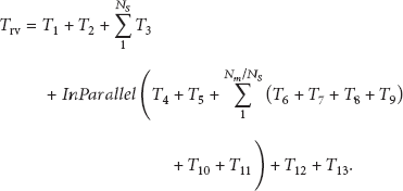
InParallel indicates that sequences are executed simultaneously over multiple stationary nodes. Therefore we can simplify (4) in the following manner:

Some sequences can be summarized as a constant value C:

Following some experiments, we set
The parameters and their descriptions for collaboration services.

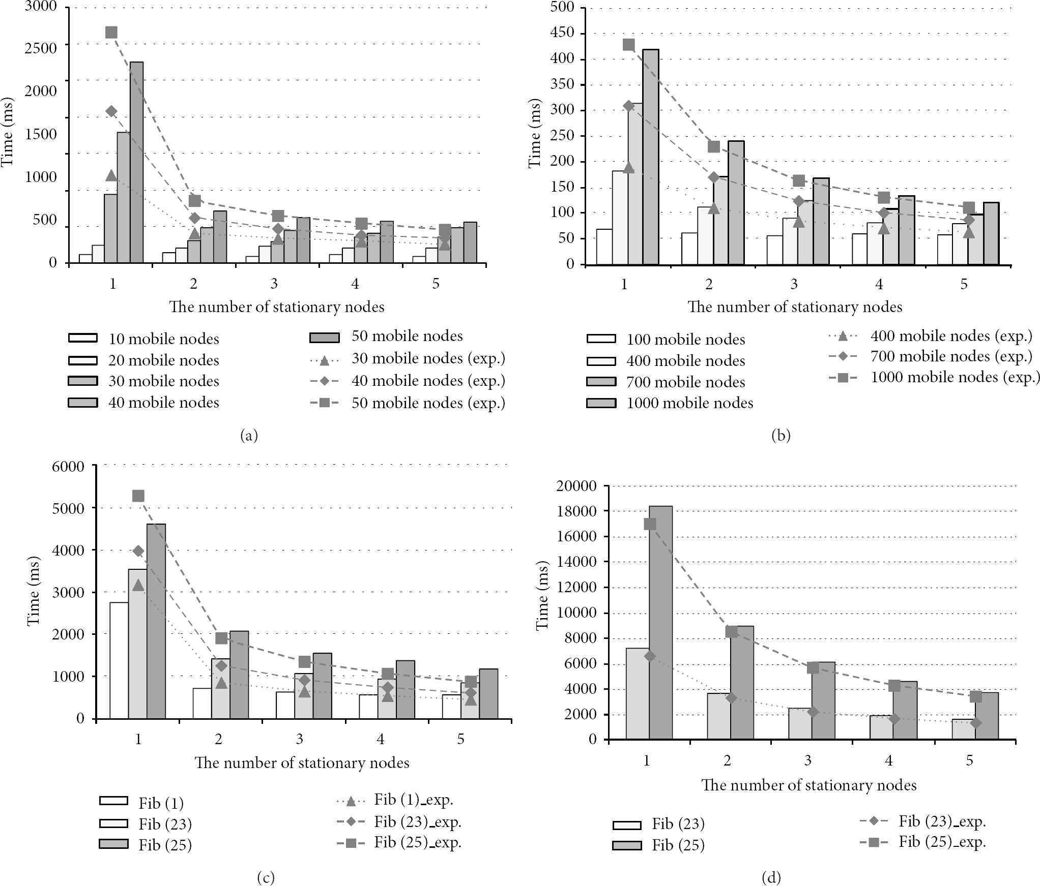
Test results for the voting service (average of 10 runs): (a and b) variation in response time with number of stationary and mobile nodes; (c and d) variation in response time with processing overhead and the number of stationary nodes; (a and c) in the real environment; (b and d) in the simulation.
To measure the traffic distribution, we evaluated the response time by varying the number of stationary nodes between one and five and the number of mobile nodes between 10 and 50 in the real environment (Figure 11(a)). In the simulation, we used up to 1,000 mobile nodes (Figure 11(b)). The locations of the mobile nodes were uniformly distributed over all the stationary nodes. In the real environment, the response time was rising significantly when only one stationary node and more than 30 mobile nodes were used. The cause was the traffic of mobile nodes flowing into a stationary node. The traffic was beyond the communication or memory capacity of the transceiver attached to the stationary node. Due to this, retry counts increased significantly as shown in Table 3. If retry counts increased, performance rapidly decreased because the retry delay was fixed at 100 ms and was much higher than typical communication. In comparison, with more than two stationary nodes, it was below the maximum capacity, so the result shows that performance gradually increased. The simulation shows the performance of middleware itself well. When only one stationary node was used, the response times were 314 ms for 700 mobile nodes and 418 ms for 1,000 mobile nodes. When five stationary nodes were used to distribute service traffic better, the response times were 98 ms and 120 ms, respectively. This result indicates that the middleware handles traffic distribution well. The decrease in response time with the increasing number of stationary nodes is due to the distribution of traffic through multiple stationary nodes with the expansion of service coverage.
Retry count in the voting service per stationary node (average of 10 runs in the real env.).

To measure service-processing distribution, we evaluated response time by changing service-processing overhead and the number of stationary nodes. The results of this experiment are shown in Figure 11(c) with 50 mobile nodes for the real environment and in Figure 11(d) with 400 mobile nodes for the simulation. To vary the service-processing overhead, a series of Fibonacci numbers was calculated in the “DoProcess” step as shown in Sequence 9 of Figure 7. It takes 16 ms to call the function fib (23) and 42 ms for a fib (25). Like the previous experiment, we can observe that the performance increases following the increase of the number of stationary nodes, and we can clearly recognize this tendency as the service overhead increases. The results indicate that the middleware effectively deals with the distribution of network traffic and service processing among multiple stationary nodes.
We can indirectly observe one more result in this experiment. The network architecture is the same as the traditional centralized architecture [12] when using only one stationary node. In other words, all graphs of one stationary node in Figure 11 indicate the performance of the centralized approach. Even though the capability of the server is better than the stationary node, we anticipate that the performance of the centralized approach decreases rapidly as the number of mobile nodes increases due to traffic bottlenecks on the paths to the server.
(B) Tracking Service. As shown in Figure 8, the performance of the tracking service can be represented by the following formula. The token transaction time, or simply the transaction time 

Some sequences can be summarized as a constant value C:

Following some experiments, we set

Test results for the tracking service (average of 10 runs): (a) variation in token transaction time with number of mobile nodes (with five stationary nodes) and (b) transaction time for each of the stationary nodes (with 5,000 mobile nodes).
Due to the practical limitation of moving multiple mobile nodes simultaneously in a real environment, we only had to evaluate the tracking service in the simulation. Figure 12 shows the results for the evaluation of the tracking service. The result could show collaborative performance among the service agents with heavy context exchange. The number of stationary nodes was fixed at five, and the mobile nodes were uniformly distributed to all stationary nodes similarly to the voting-service experiment. When a mobile node receives a message to move to the next location, it moves after a 5- to 15-second delay, randomly chosen to mimic the realistic movement of mobile objects. Figure 12(a) shows the variation in the token transaction time with the number of mobile nodes.
To check the performance, transaction logs were collected and analyzed. Figure 12(b) shows the transaction time of each of the stationary nodes when tracking 5,000 mobile nodes. Transactions were processed in 18.83 ms to 21.98 ms. That means that traffic and processing were well distributed over the five stationary nodes under the DRAS.
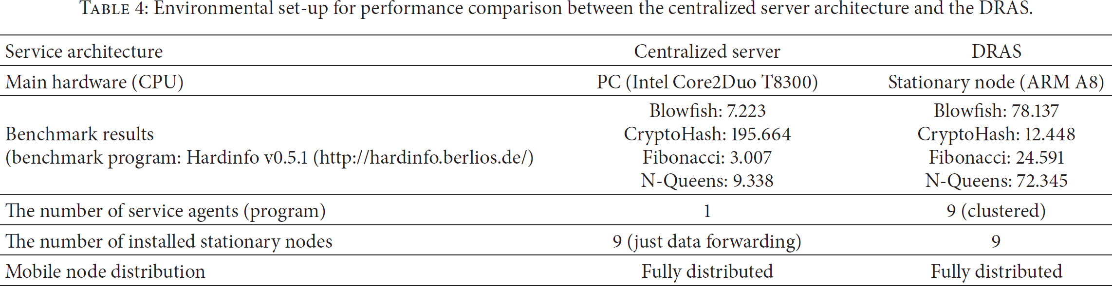
(C) Performance Comparison. The performances of the voting and tracking services between the centralized server architecture, as shown previously [12], as well as the DRAS were evaluated in the simulation in order to obtain clear and practical comparison results. Table 4 shows the environmental set-up for the performance comparison. The PC is the same hardware that was used as a server in our previous research. First of all, the hardware was evaluated to observe differences in performance. The benchmark results of the server were 8 to 15 times better than those of the stationary node. (CryptoHash result is in MiB/second. Higher is better. All other benchmark results are in seconds. Lower is better.) Nine stationary nodes were used in the test-bed of both the centralized server architecture and the DRAS. In the centralized architecture, the installed stationary nodes just forward the data received from mobile nodes to the server and it will process the requested service.
Environmental set-up for performance comparison between the centralized server architecture and the DRAS.
The mean execution time for the voting service was evaluated, and the sequences are shown in Figure 7. Figure 13(a) shows the results of the performance comparison between the server (with CNTR notation) and the DRAS (with DRAS notation). The results indicate that the centralized architecture shows better performance than the DRAS when the computation overhead is low (100~200 mobile nodes). On the other hand, the DRAS shows better performance than the centralized architecture when the computation overhead is high (400~500 mobile nodes).

The performance comparison between the centralized server architecture and the DRAS (average of 10 runs): (a) voting service and (b) tracking service.
To compare the performance of the tracking service in two architectures, we evaluated the mean execution time for querying the current locations of other nodes. In addition, to observe performance in a heavy network environment, the LIDx period was changed to 1 sec from 5 sec (simply speaking, the traffic is increased 5-fold). A mobile node sends a request message to the stationary node in order to find the current location of other mobile nodes. In the centralized approach, the message is routed to the server and the result will be routed to the mobile node through the stationary node. In the DRAS, the stationary node sends a request message to the other stationary nodes in the service cluster and collects the result. Finally, the result is routed to the mobile node. Figure 13(b) shows the results of the performance comparison between the server (with “CNTR” notation) and DRAS (with “DRAS” notation). The results show that the centralized approach has a better execution time than the DRAS at less than 5,400 mobile nodes due to a difference in hardware performance and simple service sequences, although the performance difference was small. On the other hand, execution time increased sharply when 5,500 mobile nodes were used, and eventually the service was stopped due to a thrashing problem when more than 5,500 mobile nodes were used. The DRAS can support up to 5,900 mobile nodes without a sharp increase in mean execution time.
8. Conclusions
In this paper, we proposed the DRAS, a special middleware architecture based on service agents. The agents can be distributed in the form of Erlang processes in the stationary nodes and can provide real-time service responses by the distribution of network traffic and service processing. The DRAS can expand and contract the service area dynamically by generating and destroying service agents in the stationary nodes near the mobile node. Erlang-based implementation reduces the implementation complexity despite complex coupling among agents.
To verify the DRAS and to evaluate its performance, two collaboration services were implemented: the voting service, which can collect and confirm the opinions of service users, and the tracking service, which can follow the trajectories of multiple mobile nodes in real time. The results show that the middleware deals effectively with the distribution of network traffic and service processing among service agents. We confirmed that the overhead of the reconfigurable process is considerably low, even though the number of stationary nodes is increased. We can indirectly observe that the DRAS is better than the traditional centralized approach by comparing when only one stationary node was used (centralized approach) and when multiple stationary nodes were used (DRAS) in the voting service. To compare performance between the centralized approach and the DRAS more clearly, we evaluated the average execution times of the voting and tracking services. Although the hardware for the server in the centralized architecture was better than that of the stationary node, the DRAS showed better performance, particularly when the computation overhead and network traffic were heavy and increasing. According to our evaluation, we conclude that the proposed DRAS middleware is better than the traditional centralized one, and we can suggest the DRAS as a realistic solution for indoor location-aware applications requiring a large number of mobile nodes and complex collaboration.
We intend to continue to develop the DRAS and apply it to self-organizing applications [34–36] that need fast response and complex collaboration among a large number of mobile nodes. It can be expected that the characteristics of the proposed DRAS, such as effective traffic distribution, service processing, and dynamic service coverage reconfiguration, can be of great assistance in that service domain.
Footnotes
Conflict of Interests
The authors declare that there is no conflict of interests regarding the publication of this paper.
Acknowledgment
This work was supported by the IT R&D program of MSIP/KEIT (10041145, Self-Organized Software Platform (SoSp) for Welfare Devices).