
Abstract
This paper reports an energy harvester suitable for self-powered wireless sensor network (WSN) nodes consisting of a piezoelectric cantilever, an energy harvesting circuit, and a storage capacitor. Having the same size as a credit card, the proposed WSN nodes can be easily integrated into various applications, such as motor and air conditioning equipment. The WSN node is powered by an integrated bimorph piezoelectric generator that harvests energy from ambient vibration. The paper has developed a method to optimize the harvester parameters to attune it to the dominant vibration frequency. Tests carried out on the proposed harvester show that the proposed design can meet the energy requirements of a WSN node and achieve an efficiency of 79%.
1. Introduction
Wireless sensor networks have attracted great interests over the past few decades. With the advance in integrated circuits and MEMS technology, low cost, small size, and low power circuits and sensors have seen tremendous progress in research and development, which makes the construction of large-scale WSN possible. Compared to wired systems, wireless systems can be used more widely due to their flexibility. Once deployed, WSN nodes can be routed and connected without changing their physical layout. One concern about WSN nodes is their power supply system [1–3], and the power demand is generally in the order of tens of μW to mW. Conventional power source for WSN nodes is chemical batteries. However, the application of batteries in WSN has been limited due to their large size, limited working life, and replacement cost. Therefore, it is preferred that the WSN nodes have the ability to generate energy from ambient environment. The self-powered WSN nodes have become a research focus in view of its advantages, including simple structure, heatless, no electromagnetic interference, and almost unlimited working life. Therefore, major efforts have been devoted to research in this and related areas in many countries, especially the United States, Britain, and The Netherlands.
Vibration energy harvesting, as a promising solution to powering WSN nodes, has been studied comprehensively over the recent years. Mathers et al. [4] reported a piezoelectric energy harvester based on the piezoelectric device (PMN-PT), and the maximum output power obtained under the 1.3 kHz excitation frequency is about 0.3 mW. Gu [5] presented a low-frequency piezoelectric harvester with a resonance frequency of about 20.1 Hz with the maximum output up to 1.53 mW; but the harvester length is increased to 100 mm. The piezoelectric thin film cantilever energy harvester based on MEMS technology has been realized by Reilly and Wright [6]. The PZT layer thickness is 1 μm, and the maximum output is 24.5 pW near the resonant frequency (967 Hz). Jeon et al. [7] presented the structure of 1 μm-thick PZT cantilever, with a size of approximately 170 × 260 × 2.4 μm3 and a maximum power output of 1 μW near the resonant frequency of 13.9 KHz. Kok et al. [8] studied the structure of the thick film multimorph cantilever with a PZT thickness of 55 μm; the output is up to 40 μW at a working frequency of 400 Hz.
Most researches [9–13] focus on the output power increase, size reduction, operating frequency reduction and energy harvesting circuit efficiency improvement, and so forth. However, integrated design, fabrication, and test of the piezoelectric energy harvester are also worth studying. This paper describes an improved piezoelectric vibration energy harvester consisting of an integrated bimorph piezoelectric cantilever, energy harvesting circuit, and a storage capacitor. A design method has been developed in this paper to attune the energy harvester to dominant environment vibration frequency. Tests have also been carried out on the performance of the proposed harvester design.
The paper is organized as follows. Section 2 describes the design and fabrication methodology of the energy harvester, followed by experiment tests performed on the proposed design in Section 3. Conclusions are provided in Section 4.
2. Design and Fabrication
2.1. Energy Consumption Analysis of WSN Nodes
The self-powered WSN node consists of energy harvester, sensor, microcontroller, and wireless transceiver as shown in Figure 1. The energy harvester provides power for all other components.

Diagram of wireless sensor network node.
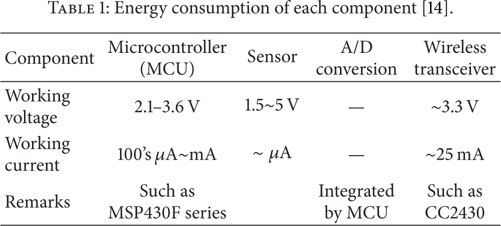
Energy consumption of the WSN node is the sum of power consumed by its individual components. Typical energy consumption of its components is shown in Table 1. It can be seen from Table 1 that wireless transceiver module accounts for more than 95% of the total energy consumption which is estimated at about 100 mW. Therefore, if the energy harvester could provide a constant power of 100 mW for certain period with a stable output voltage of 3.3 V and a current of 30 mA, it would be sufficient for WSN node to produce periodic transmission as wireless transceiver usually works for about tens to hundreds of milliseconds at a time in a periodical manner.
Energy consumption of each component [14].
2.2. Harvester Design
The energy harvester mainly consists of a piezoelectric generator and an electronic circuit for energy harvesting. The piezoelectric generator generates energy from vibration waves that permeate in the ambient environment. To generate the maximum output power, the generator should be designed to work at resonance with the dominate frequency of the environment. Therefore, the optimal frequency of the energy harvester may vary according to the specific application and the environment in which it is designed to operate. In this paper, we consider the wireless sensor network nodes in industrial applications. The industrial first-order (dominant) resonant frequency is 50 Hz in China. Therefore, the generator in this case aims to work at a resonant frequency of about 50 Hz.
Based on the analysis of previous work [15] reported in the literature, a bimorph piezoelectric cantilever structure is adopted in this paper. Figure 2 shows the bimorph piezoelectric cantilever. The top and bottom layers are PZT, and the elastic stainless steel is located in the center. The effective length of the cantilever is 42 mm. The thicknesses of the PZT and the elastic layer are 200 μm and 100 μm, respectively. A 3 μm-thick epoxy resin is used as an intermediary adhesive layer between the PZT and elastic layers. Upper and lower PZTs are at different polarization states with the electric field of 3 kV/mm. Two PZT layers are connected in parallel to maximize the output current.

Structure of the bimorph piezoelectric cantilever.
In order to adjust the first-order resonant frequency of the cantilever, we usually put a mass on the free end of the cantilever. According to the proposed method in [8], the influence of the mass weight on the first-order resonant frequency can be calculated quantitatively. The physical properties and geometric parameters used in the calculation can be found in Table 2. Figure 3 shows that the first-order resonant frequency of the cantilever declines rapidly with the increase of mass weight. When the mass is set at about 9 g, the theoretical first-order resonant frequency of the cantilever is about 50 Hz, which is equal to the dominant resonant frequency in China.
Physical properties and geometric parameters of cantilever.


Influence of the tip mass weight on the first-order resonant frequency.
2.3. Harvester Fabrication
According to the harvester design, the piezoelectric coefficient, 
It can be shown that when vibration frequency matches resonant frequency, that is, 
According to (2), the higher the
In order to enhance the bonding performance of the bulk PZT plate with the elastic layer (stainless with a thickness of 100 μm was chosen), a thin film of epoxy resin with a thickness of a few micrometers was used as an intermediate layer. A special bonding process was adopted to achieve good bonding effect. Detailed description of the bonding process can be found in our previous work [16, 17].
Following the bonding process, the sample was diced to the required size, and an insulation mask was used to cover the top electrode. Figure 4 shows the optical image of the fabricated PZT bimorph harvester.

Photo of the fabricated PZT bimorph harvester with top and bottom electrodes as shown in the image.
2.4. Harvesting Circuit
Energy harvesting circuit is an important part of the energy harvester. Its performance directly affects the final energy conversion efficiency of the energy harvester. Chip LTC3588-1 is selected for this application as it offers a complete method for high output impedance energy harvesting (e.g., piezoelectric transducer). The chip LTC3588-1 is integrated by a low-loss full-wave bridge rectifier and a high-efficiency buck converter. Therefore, this chip is chosen as the main chip of energy harvesting circuit due to its good efficiency, circuit size, and high degree of integration. Figure 5 gives the detailed design of the energy harvesting circuit.

Energy harvesting circuit based on LTC3588-1 (the output voltage is designed to be 3.3 V).
Generally speaking, the piezoelectric energy harvester has characteristics of high voltage and low current output. Therefore, the storage capacitor of the harvesting circuit should have enough withstand voltage. In addition, capacity of the capacitor should be selected according to the energy consumption requirement of the WSN nodes. Due to the energy supply limitation, WSN nodes usually work in a periodical fashion. A continuous working time (mainly by wireless transceiver) is about hundreds of milliseconds. Suppose it is 300 milliseconds, the energy demand required for a continuous working period can be calculated as follows:

Let 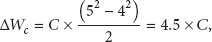
In order for the energy harvester to provide sufficient energy for the WSN to function properly, the following condition should be satisfied: 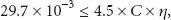
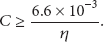
If the efficiency η is 75%, the capacitance C should not be less than
2.5. Harvester Integration
Figure 6 shows the photo of the actual piezoelectric energy harvester connected with a RF transmitter CC2430. The energy harvester has a dimension similar to a credit card, that is,

Integration of the energy harvester with CC2430 for experimental tests.
3. Experiment Tests
3.1. Experimental System
Figure 7 shows the experimental system diagram. The system consists of a waveform signal generator, a power amplifier, a shaker, an accelerometer, an oscilloscope, and a piezoelectric energy harvester. The waveform generator can generate sine wave signals with adjustable frequency. The generated signal is amplified by the power amplifier to excite the vibration of the shaker. The piezoelectric energy harvester fixed on the shaker will generate sine AC voltage under right vibration frequency. The sine AC voltage is used in the energy harvesting circuit.

Testing system of piezoelectric energy harvester.
To make best use of the power generated by the energy harvester, a step-up voltage regulator, LTC3588-1 from Linear Technology [18], has been used. It is able to convert the input voltage with a range of 2.7 V–20 V to a constant output voltage of 1.8/2.5/3.3/3.6 V which is capable of powering most ICs available on the market and the output current can reach up to 100 mA. Furthermore, it has an efficiency rate of up to 91% and a typical quiescent current of less than 95 nA, which makes the system power efficient.
A low power microcontroller (the CC2430 from Texas Instruments (TI) [19]) was selected to provide the microcontroller and RF solution. The CC2430 integrates an 8051 core CPU and an RF transceiver which is compatible with 2.4 GHz IEEE 802.15.4 and ZigBee protocols. Wireless sensor networks of smart tags can be easily built based on the CC2430 platform. Typically, it has a current consumption of 26.9 mA when the transceiver is active and so has to be duty-cycled in energy constrained applications. The typical work voltage for CC2430 is 3.3 V.
Accelerometer is used to measure the acceleration of the input vibration. During the experiment, the oscilloscope will monitor various input signals.
3.2. Experimental Results
Firstly, the frequency characteristics of the fabricated harvester were tested. As an example, the fixed mass in this case is 9 g. After keeping the amplitude and offset of the sine wave constant, we changed the output signal frequency of the waveform generator continuously. And RMS voltage of piezoelectric energy harvester was recorded using the oscilloscope. Figure 8 gives the frequency characteristics of the harvester.
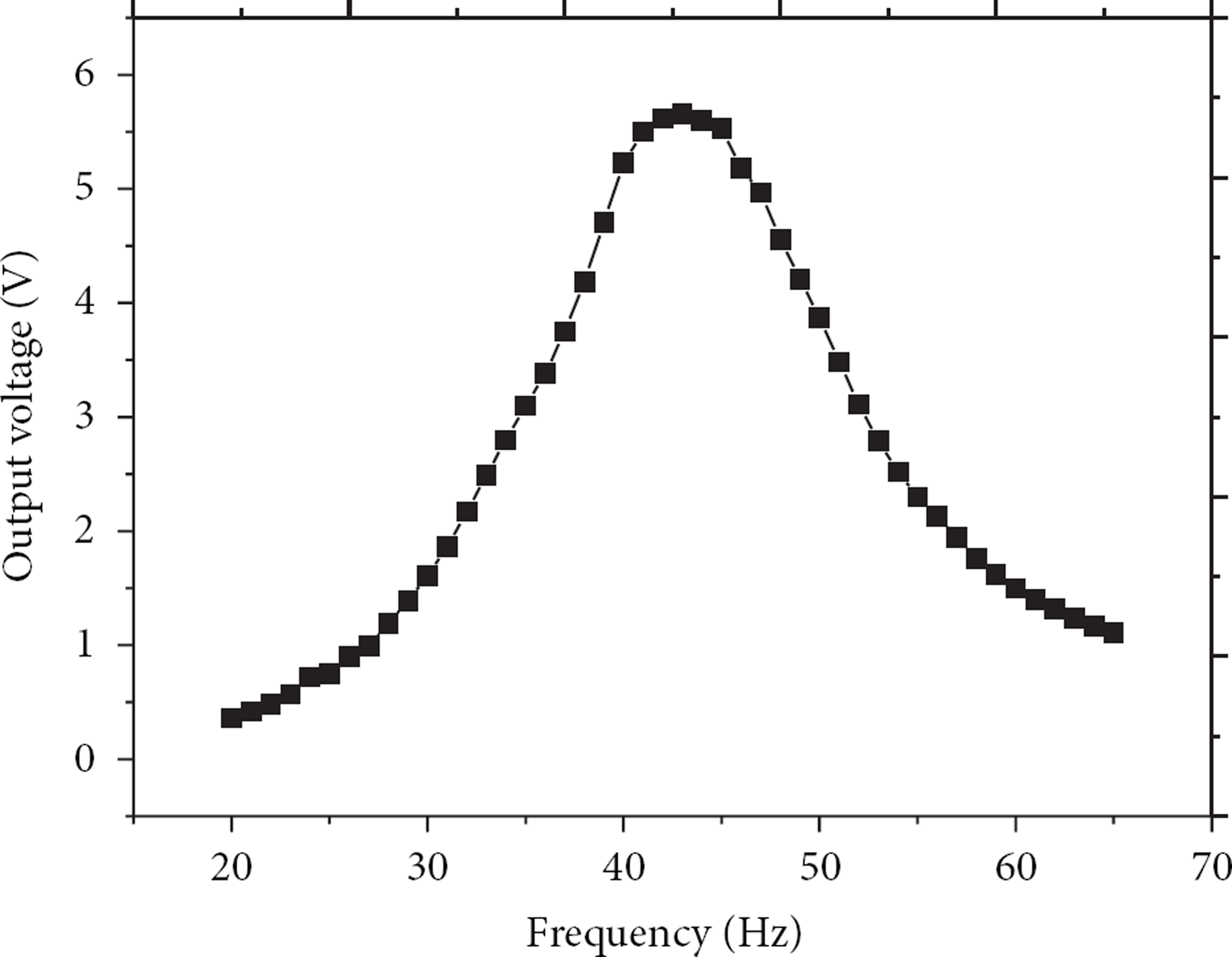
Sweeping curve of the piezoelectric energy harvester.
The experimental results show that the first-order resonant frequency and the 3 db bandwidth of the energy harvester are about 44 Hz and 16 Hz, respectively. The measured resonant frequency is 6 Hz away from the expected value. There are a number of reasons why experimental and theoretical results are different. However, main factors are likely to be the inaccurate estimate of material properties and the method of installing mass, especially for the bonding strength between the piezoelectric cantilever and the mass. In the experiment, the mass was glued to the cantilever tip using double-faced adhesive tape, which leads to weak paste effect. While the cantilever vibrates at its resonant frequency, the interaction between contact surfaces may have changed the harvester's inertia and as discussed above the inertia coefficient is related to the resonant frequency.
Figure 9 presents relationship between the RMS output voltage and the vibration acceleration of the energy harvester. The linear relationship agrees with the theoretical analysis. The voltage across the storage capacitor can be charged to 5 V at the maximum acceleration of about 0.7 g. The required maximum acceleration can be reduced to 0.35 g when the two PZT layers are connected in series.
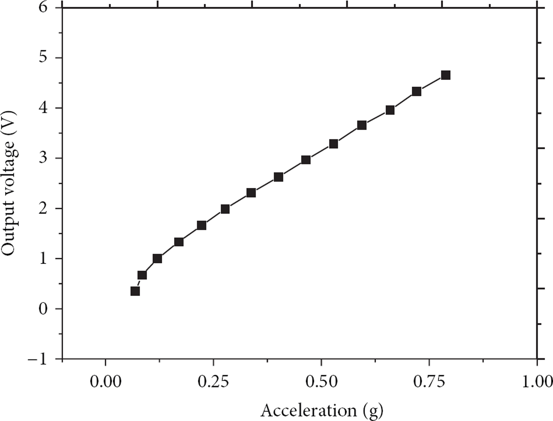
Relationship between the voltage and the acceleration of the cantilever.
Finally, the overall performance of the energy harvester was investigated and discussed. The maximum acceleration is set at 0.9 g with capacitor capacitance of 0.01 F and shaker frequency of 44 Hz. When the voltage across the capacitor reaches 7.5 V, it starts supplying power to load CC2430. The output current of the circuit is 33 mA. As shown in Figure 10, the energy harvesting circuit maintains a constant output voltage of 3.3 V (

Output power of the proposed harvester.
4. Conclusions
The paper proposed an energy harvester suitable for industrial application based on bimorph piezoelectric cantilever. The experimental tests were performed on the energy harvester with optimized parameter design. Test results show that the energy harvester can meet the energy needs of WSN nodes. However, it should be noted that the energy harvester was tested in an idealized environment with no background harmonic frequencies and noises considered that would be present in the actual working environment. The influence of these noises on the energy harvester performance requires further investigation. In addition, the proposed energy harvester achieved an efficiency of about 79%. Main factors that affect the efficiency include inherent loss in piezoelectric material, bonding mass, charging-discharging of storage capacitor, and the electronic loss. Further research work will be carried out to improve the harvester efficiency and reduce the losses in these areas.
Footnotes
Conflict of Interests
The authors declare that there is no conflict of interests regarding the publication of this paper.
Acknowledgment
This work was supported by the National Natural Science Foundation of China (51007007 and 51107010).