
Abstract
The transient performance of centrifugal pumps during the startup period has drawn more and more attention in recent years due to urgent engineering needs. In order to make certain the transient startup characteristics of a high specific-speed prototype centrifugal pump delivering the gas-liquid two-phase flow, the transient flows inside the pump are numerically simulated during the startup period using the dynamic slip region method in this paper. The results show that the difference in heads mainly focuses on the later stage of the startup period when the pump is used to transmit the pure water and the gas-liquid two-phase flow, respectively. The existence of the gas phase makes the head less than that of delivering pure water. The nondimensional head coefficient is very high at the very beginning of the startup period and then quickly drops to a stable value. The continuous variation of the attack angle at the leading edges of blades is the main reason for evolution of the internal flow field during the startup period.
1. Introduction
Centrifugal pumps have been widely used to transport various media for several hundred years. They usually operate at stable working conditions; namely, the rotational speed, flow rate, pressure, and so forth are invariable or vary very slowly. As is known to all, some transient processes, such as startup and stopping, are inevitable and existent. With the development of engineering needs, the transient performances have been deeply studied by more and more scholars in the past 30 years. Tsukamoto and Ohashi studied the transient characteristics of a centrifugal pump during the starting period by experimental study and theoretical calculation [1]. The results show that the impulsive pressure and the lag in circulation formation around impeller blades are the main reasons for the difference between dynamic and quasi-steady characteristics. Thanapandi and Prasad investigated the dynamic behavior of a volute pump during normal startup and stopping periods and also originally analyzed the dynamic performances using the method of characteristics [2]. Lefebvre and Barker tested four transient cases of a prototype mixed-flow pump during acceleration and deceleration periods [3]. The results show that the quasi-steady hypothesis in predicting the pump transient performance is unreliable. Dazin et al. proposed a new method for predicting the transient behavior of turbomachinery based on the angular momentum and the energy equations [4]. The results show that the transient behavior of a pump impeller depends not only on the acceleration rate and flow rate but also on velocity profiles and their evolution during transient periods. For a low specific-speed prototype centrifugal pump with a closed impeller and an open impeller, respectively, Zhang et al. tested the external performance of the pump model during rapid starting periods through experiments and analyzed the variation of the nondimensional head and the nondimensional flow rate with time [5, 6]. Wu et al. studied the transient flow characteristics of a centrifugal pump when the discharge valve is rapidly opened by numerical simulation and experimental test [7]. Liu et al. numerically studied the stopping characteristics of a radial vane pump, wherein the volume of fluid (VOF) model was used to better simulate the interaction between water and air in the tank [8].
It is seen that all the abovementioned studies on transient characteristics are limited to using water as working fluid. However, this is not always the case in reality. The transmitted media are various, such as solid-liquid two-phase flow and gas-liquid two-phase flow. In previous works, on the condition that the transmitted medium is the solid-liquid two-phase flow, the authors of this paper have carried out numerical investigation on transient startup characteristics of a pump model [9]. It is found that the differences of transient startup performance are extremely obvious between water and solid-liquid two-phase flow. As is well known, the centrifugal pumps transporting gas-liquid two-phase medium are extensively used in many engineering applications. However, up to now, the study on the transient startup behavior related to gas-liquid two-phase flow has not been seen yet. The objective of this paper is to reveal the transient startup characteristics of a prototype centrifugal pump delivering the gas-liquid two-phase flow.
2. Calculation Model and Method
2.1. Pump Model
The calculated model is a volute centrifugal pump. Its rated parameters are as follows: flow rate 106.8 m3/h, head 18 m, and rotational speed 2880 r/min. Table 1 shows the main geometric parameters of the pump; more detailed parameters specification can be seen in [2, 9].
Main geometric parameters of the pump model.

2.2. Multiphase Flow Model
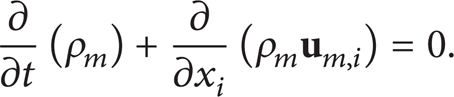
In this paper, the transmitted media are the gas-liquid two-phase flow. As such, choosing the algebraic slip mixture model (ASMM) [10] as the multiphase flow model to calculate the gas-liquid two-phase flow inside the pump model, the continuity equation is given as follows:
The equation for mixture momentum (jth component) is as follows:

The volume fraction equation for the secondary phase is as follows:

The above equations are formulated in terms of the mixture density, ρ
m
, mixture viscosity, μ
m
, and the mass-averaged mixture velocity,

where
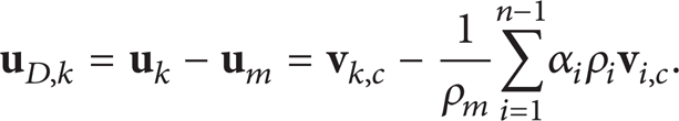
In the above equation,

The gas phase in the gas-liquid two-phase flow is assumed to be uniform sphere with unchangeable physical property. The density and the diameter of gas particles are 1.225 kg/m3 and 0.1 mm, respectively. The distribution of the gas-liquid two-phase flow at the inlet of the pump is assumed to be uniform before startup. The volume fraction of the gas phase is 10%. The liquid phase is the pure water under the standard condition.
2.3. Computational Domain and Mesh
The computational domain and the grids generated by commercial code GAMBIT 2.2.30 are shown in Figure 1. The grids in the impeller and the volute are tetrahedral; the rests in the suction chamber and the extended domain at the outlet of the pump are hexahedral. The grid dependency study is carried out for the present model; it is found that the head correlation is less than 1% and there is almost no difference among the flow fields. Consequently, the influence of the grid numbers on the numerical results can be ignored. The final grid number used in the computation is 1 030 000. The value of y + is taken as about 30 near the boundary wall. The present grid number can be used to correctly predict the external performance and capture the macroscopical basic flow phenomenon. Moreover, “EquiAngle Skew” and “EquiSize Skew” of all meshes are less than 0.85; therefore, the grid quality is satisfied as well.

Computational domain and grids.
2.4. Numerical Method
The commercial code FLUENT 6.3.26 is employed to calculate the transient flow inside the pump during the startup period. Applying the dynamic mesh method to accomplish the numerical simulation of unsteady flow in this paper, it has been verified that it is able to successfully simulate the pumps’ starting and stopping processes [8, 9]. In the process of startup of the pump model, the measured rotational speed and flow rate in the experiment are fitted as the functions of time and then are written into FLUENT program by means of user defined function (UDF). As such, the impeller will rotate in the light of the given variation of the rotational speed. Meanwhile, the tested flow rate is changed to the inlet velocity condition and then is implemented at the inlet of the pump. The outflow is specified as the outlet boundary condition, and the flow rate weighting is set to be 1.0.
The RNG k-ε turbulence model including the influence of high strain rate and large curvature overflowing has been widely verified to be suitable to simulate the flow inside the pump [9]. Consequently, it is employed to close the Reynolds average Navier-Stokes equations. The no-slip boundary condition is applied on all the walls due to viscosity. The standard wall function is also used to deal with the flow near the walls. The SIMPLE algorithm is used to solve the discretized equations, including velocity and pressure update, to enforce mass conservation, and eventually to obtain the pressure field. The time-dependent term is in the first order implicit scheme. The second order upwind scheme is used to discretize the convection terms, and the central difference scheme is applied for the diffusion terms. The under-relaxation factors of all the fluid flow variables are adopted as the default setting of FLUENT. The residual tolerances are set as 1 × 10⁻⁴. The time step is 1 × 10⁻⁴ s, and the whole startup time was 1.6 s. Calculations are parallelly performed on a Windows PC cluster of four Intel Xeon processors (3.2 GHz). The simulation of the startup requires approximately 12 days.
3. Results and Discussion
3.1. Validity of Numerical Method
In the case that the pumped medium is the pure water, the authors of this paper calculated the external performance of the pump and compared it with the experimental results [9]. It is seen from Figure 2 that the predicted head by numerical simulation is consistent with the experimental one. The predicted head is slightly higher above the experimental one with an average relative error as small as approximately 5%. This result verifies that the numerical solving method employed is fully feasible; thus, the corresponding results should be reliable. In the following sections, the calculation for gas-liquid two-phase flow would be carried out based on the present numerical method.
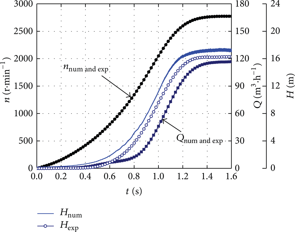
Comparison of predicted head and experimental head.
3.2. Pump Head
For flow acceleration inertia at the transient operating conditions, the total instantaneous head includes the flow inertial head and the steady head [1]. Figure 3 shows the comparison results of the predicted pump heads in the case where the pumped media are the pure water and the gas-liquid two-phase flow, respectively. As a whole, the two head curves display similar variation tendency, and both of them are the same until approximately 0.70 s after startup. As time is beyond this period, the head for delivering gas-liquid two-phase flow becomes lower than pure water and the difference between them becomes more obvious with the rising rotational speed. Clearly, the existence of gas phase greatly changes the flow inside centrifugal pump. At about 1.6 s, the rotational speed rises to the maximum and no longer changes. Meanwhile, the average head for delivering pure water is about 17.24 m, while the head for delivering gas-liquid two-phase flow is about 15.19 m. The maximum difference in heads is 2.05 m. In addition, it is found that the fluctuations in two heads are similar, and the fluctuation values are about 0.5 m.

Comparison of predicted heads in the case of water and gas-liquid two-phase flow.
3.3. Nondimensional Head
Clearly, each flow parameter varies greatly with the rising rotational speed during the startup period; namely, these parameters are dependent on the rotational speed. Therefore, the effect of the rotational speed should be excluded from them in order to have a better understanding of the transient behavior. As such, a nondimensional head coefficient is defined as follows:

where u2(t) is the impeller tip speed, u2(t) = πD2n(t)/60, and n(t) stands for the instantaneous rotational speed. Clearly, the nondimensional head coefficient should be independent of the rotational speed. Figure 4 shows the time history of the nondimensional head coefficient during the startup period in the case of gas-liquid two-phase flow.

Nondimensional head coefficient during the startup period.
It is seen from Figure 4 that, at the very beginning of startup period, the nondimensional head coefficient exhibits a global maximum and then quickly drops against time for about 0.1 s. As is well known to us, the fluid is stationary before startup, and the abrupt rotating impeller generates a pressure impact on it. Therefore, such an action is responsible for this transient effect. When the time is beyond about 0.3 s, the nondimensional head coefficient no longer changes in spite of the fact that the rotational speed continuously rises.
3.4. Pressure Characteristics
Figure 5 shows the time histories of the static pressures and the dynamic pressures at the inlet and the outlet of the pump during startup period in the case of gas-liquid two-phase flow. For the static pressure at the inlet of the pump, its profile does not show a marked variation in the whole process of startup. However, for the static pressure at the outlet of the pump, the average pressure gradually rises as the rising rotational speed during the startup period. It is found that the variation tendencies between them are very similar; namely, both of them display relatively good synchronization in time. Meanwhile, the rotor-stator interaction between the stationary volute and the rotational impeller makes the static pressure at the outlet show obvious fluctuation characteristic, especially at the later stage of startup. It is well known that the static pressure at the outlet of a pump mainly determines the magnitude of the head. Figure 3 and Figure 5(a) together exhibit this characteristic. For the present pump model, the discharge diameter, 76 mm, is less than the suction diameter, 102 mm. Therefore, the average velocity at the outlet of the pump is higher than that of the inlet according to mass conservation. As such, the dynamic pressure at the outlet of the pump is always higher than that at the inlet theoretically. The calculation results show that the dynamic pressures at the inlet and the outlet are very small due to the relatively low flow rate before 0.8 s after startup. Subsequently, the two dynamic pressures rapidly rise with the increasing flow rate.
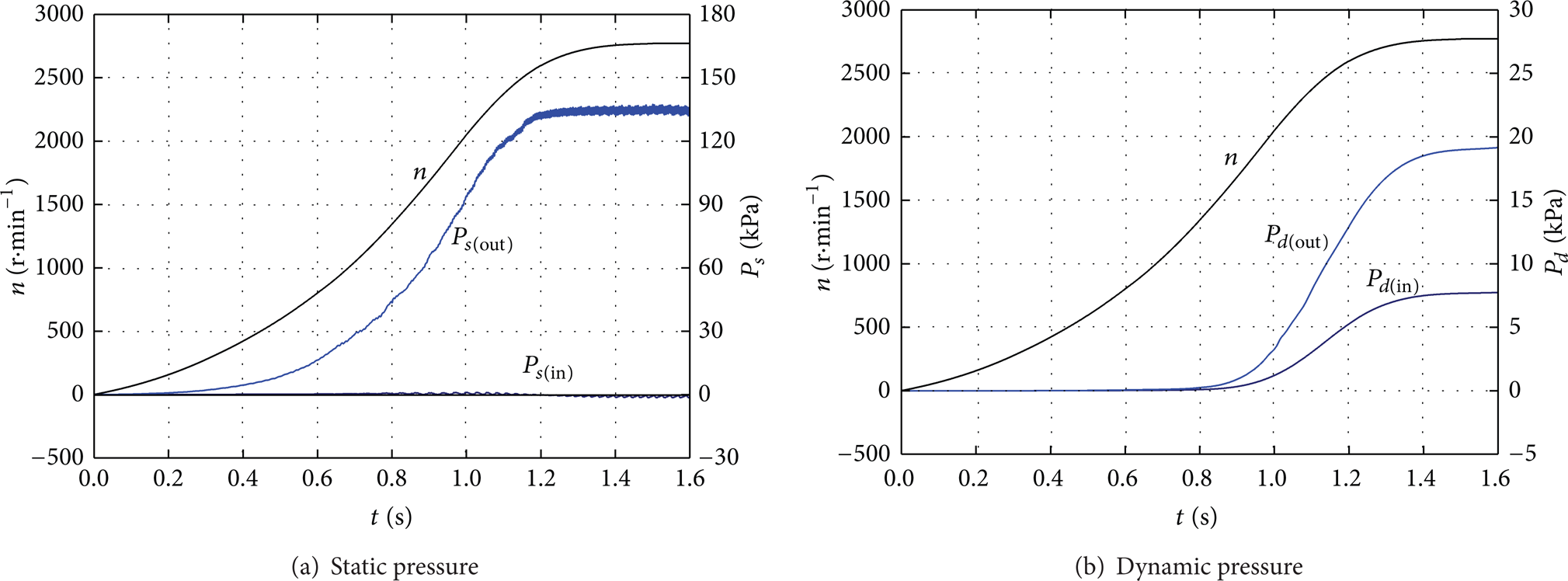
Pressures characteristics at inlet and outlet of pump during the startup period.
3.5. Impeller Shaft Power and Dynamic Reaction Force
On the condition that the transmitted medium is the gas-liquid two-phase flow, the calculated impeller shaft power and the impeller dynamic reaction force of the pump during the startup period are shown in Figure 6, wherein the definition of the impeller shaft power is as follows:

where M(t) is the instantaneous torque on impeller and is obtained by numerical calculation.

Impeller shaft power and dynamic reaction force during the startup period.
It is seen that the impeller dynamic reaction force and the impeller shaft power show similar evolution tendencies; both of them synchronously increase with time as a whole. Before 0.6 s after startup, the impeller shaft power and the impeller dynamic reaction force are very small. As time is beyond this period, both of them rapidly rise until to each stable value. The final average dynamic reaction force and impeller shaft power are 118 N and 6.8 kW, respectively. Moreover, some slight fluctuation exists in the dynamic reaction force; the corresponding maximum of fluctuation is about 8 N.
3.6. Flow Field
Employing numerical simulation is able to obtain not only the external performance but also the internal flow field. In the case where the pumped medium is the gas-liquid two-phase flow, Figure 7 shows the evolution histories of the relative streamlines in the impeller and the total pressure contours in the whole pump during the startup period. Some basic flow characteristics are fully reflected from Figure 7. For example, the total pressure gradually increases with the increase of rotational speed. At any moment, the total pressures gradually increase from the inlets to the outlets of the impeller channels. As a whole, the total pressures on the pressure sides are higher than those on the suction sides at the same radius. Note that the total pressure finds the lowest one immediately after the leading edge of a blade at the suction side. However, the lowest absolute pressure is about 80 kPa in this case, and it is much higher than the vapor pressure of water, 2.3 kPa, at the standard condition, so as not to cause cavitation appearance at all in the present calculations.

Evolution of relative streamline and total pressure (kPa) during the startup period.
The rotational speed profile and the flow rate profile in Figure 2 are not completely similar, especially at the beginning of the startup. This fact manifests that both of them are not completely synchronous in time. Therefore, the velocity triangle at the inlet of the impeller composed of the circumferential velocity and the meridional velocity is variable during the startup period. As such, the attack angle is varied at the leading edges of blades, which would cause the internal flow field to show the corresponding evolution pattern. At t = 0.05 s, vortexes appear behind the blade leading edges. At t = 0.20 s, vortex regions greatly augment. At t = 0.40 s, vortex regions move to impeller outlet. At t = 0.60 s, vortex regions greatly diminish. At t = 0.80 s, small backflows still exist near the volute tongue. Clearly, the tongue structure plays an important role in affecting the internal flow inside the pump. When t > 1.0 s, almost no backflows are observed in all impeller channels.
Figure 8 shows the evolution histories of the gas volume fraction at the middle section during the startup period. At t = 0.40 s, the gas phase enters the impeller channels via the suction chamber, and the volume fraction is relatively low. Subsequently, at t = 0.80 s, the gas phase fills in whole impeller channels with time. At t = 1.0 s, the gas phase enters the volute domain, and the volume fraction greatly increases. At t = 1.4 s, the internal domain of the pump is filled with the gas phase, and the distribution has also been relatively uniform.

Evolution histories of gas volume fraction during the startup period.
4. Conclusions
Based on the given rotational speed and the flow rate obtained in the experiment, the gas-liquid two-phase flow inside a centrifugal pump during the startup period is numerically simulated. The calculation results not only get the external performance but also contain the internal flow fields. The calculation results show that, at the later stage of startup period, the head for delivering gas-liquid two-phase flow is lower than that of delivering the water medium. The nondimensional head coefficient is very high at the very beginning of the startup period and then quickly drops to a stable value. The evolution of internal flow field during the startup period can be attributed to the continuous change in the attack angle at the leading edges of blades.
Conflict of Interests
The authors declare that they have no conflict of interests regarding the publication of this paper.
Footnotes
Acknowledgments
The authors thank the support by the Zhejiang Provincial Natural Science Foundation of China (no. LY14E090011 and no. LY12E06002) and the National Natural Science Foundation of China (no. 51276172).