
Abstract
This paper proposes an enhanced sliding mode controller (SMC) for piezoelectric actuator based flexural mechanism (PABFM) to track desired motion trajectories. First, based on the variable structural control approach, the proposed controller is established to accommodate parameter uncertainties, nonlinearity, and unmodelled disturbances. Because the traditional sliding-mode control cannot deal with mismatched disturbances effectively, a hysteresis counterelectromotive force (CEMF) model is proposed to describe nonlinear hysteresis effect and electric-mechanical coupling of PABFM. as Similar to the CEMF voltage for a motor caused by a changing electromagnetic field due to a rotating armature, the CEMF voltage appears to PA due to polarization and molecule friction of piezomaterial. The CEMF model is identified using a charge system search (CSS). Then, the proposed SMC with CEMF compensation is studied to deal with the mismatched nonlinear disturbances. To check the consistency of the proposed SMC controller with CEMF compensation, the simulation results were compared with the experimental results. The real-time implementation validated the tracking error better than the traditional SMC.
1. Introduction
Piezoelectric actuator based flexural mechanisms (PABFM) have been designed for accomplishing ultraprecision motion with high speed in the ultraprecision positioning applications such as NANO/MEMS manipulations, because they can perform precise positioning with resolution of 1~10 nanometers at rapid response. Comparing the conventional mechanical motion mechanisms such as ball-screw stages with servo motors, PABFM possess several advantages such as zero backlash, negligible friction, high electrical-mechanical coupling efficiency, small thermal expansion during actuation, noiselessness, and easy maintenance [1, 2]. Therefore, PABFM have been extensively used in ultraprecision positioning applications, such as atomic force microscopes (AFMs), scanning electron microscopes (SEMs), and precision manufacturing [3, 4]. Speaking of the flexural stage's design, its mechanism consists of a movable stage by four parallel leaf springs with a monolithic structure [2]. Monolithic design has the advantages as follows: achieving stress-free and strain-free, more precise alignment of the stage components than other manual assembly designs and compact size [5–10]. Some related studies using PABFS in applications of NANO/MEMS manipulators and other recent applications are in the microsurgery and biomedical engineering [11–13].
Since the PA has the above advantages, creep phenomena and hysteresis effect are the two major nonlinear phenomena and they may make the controller design difficult. Feedback controllers can deal with creep phenomena of the PA. However, hysteresis phenomena are not easy to solve by traditional control, because it is the nonlinear relation between the displacement and the applied voltage. Hysteresis effect results from the polarization and molecule friction for piezo materials. Several approaches were proposed to compensate the hysteresis nonlinearity and two major categories are proposed as follows: the model-based compensation and the non-model-based compensation [14, 15]. For the model-based compensations, mathematical models can be divided into the integral type and the differential type of hysteresis model. The various integral hysteresis models, such as Preisach model [16], the generalized Maxwell-slip model [17], and Prandtl-Ishlinskii (PI) model [18], use different integral operators that capture mapping of hysteresis loops with reversal behavior using a specified number of hysteretic operators. To establish the grid plane of the major and minor loops of hysteresis, substantial computing resources and many experimental data are required.
Differential hysteresis models use nonlinear differential equations to describe hysteresis dynamics; therefore, they do not need so many experimental data as the integral hysteresis models. For example, Duhem model was developed to describe magnetic hysteresis initially and it is extended to the hysteresis in piezoelectric materials [19]. The Bouc-Wen model was proposed to describe the typical hysteresis, which can be used for many smart materials [20, 21]. Dahl hysteresis model was used to describe the friction's model and Xu and Li have adapted the Dahl model for piezoelectric hysteresis [22]. To formulate hysteresis models that are either independent or dependent on rate, the generalized Duhem model (GDM) was proposed in [23]. C.-J. Lin and P.-T. Lin reformulate the GDMs to describe the piezoelectrical hysteresis for different types of hysteresis models [24]. However, accurate parameters of hysteresis models are generally difficult to obtain and describe nonlocal memory effects. Therefore, the open-loop control only is not enough to guarantee repeatable accuracy for tracking tasks. The feedback control with the feedforward compensation is required for precision tracking.
The desired tracking accuracy can be achieved by appropriate closed-loop controls and recent examples include a neural network feedforward with PI feedback control [25], a tracking control with a feedforward compensation [26], an adaptive approximation based back-stepping approach [27], a fuzzy decentralized control using a microprocessor [28], an adaptive sliding mode control [29], a multirate control with a feedforward inverse hysteresis model [30], a combination of a nonlinear observer-based with the variable structure control, adaptive neural network control with hysteresis estimation [31], robust adaptive constrained motion tracking control [15], and tracking control with feedforward control using generalized Duhem model [24]. Liaw and Shirinzadeh proposed a robust control with force feedback to solve the constrained motion tracking problem [15]; however, using the force sensor may have two problems in some cases; the first one is to the space issue and the second is the external disturbance from the sensor's noise. Therefore, Lin et al. proposed a counterelectromotive force (abbreviated counter EMF) model to describe the hysteresis effect caused by the polarization and molecule friction of PA [32]. However, the previous work focuses on system modeling and identification and the feedback compensation of tracking tasks was not studied and discussed. In this study, an extended sliding mode controller is proposed for precision tracking tasks of the PABFM. This paper is organized as follows. Section 2 presents modeling of PABFM using a proposed CEMF model. Section 3 presents an extended sliding mode controller and the robustness of SMC is discussed. After the CEMF model has been established, the CSS-based optimization problem is investigated to obtain the parameters of the CEMF model. Section 4 presents two case studies to confirm the proposed method experimentally using the proposed sliding mode controller. Finally, Section 5 draws conclusions.
2. CEMF Model for Piezoelectric Actuator Based Flexure Mechanism
Consider a piezoelectric actuator based flexure mechanism (PABFM) stage, as shown in Figure 1, the mechanism is a monolithic structure which comprises four flexures. The FBM stage is self-designed and fabricated by a wire electric-discharge-machine (WEDM) from a piece of A7075 material. The movable stage is based on the flexural guidance mechanism. The flexures can be considered as the plane springs which connect the movable stage to the ground. The motion of the flexure mechanism is continuous, smooth, and repeatable; the flexures are practically wear-free if they are not overactuated. A piezo actuator (PA) of 20 μm-stoke (Model: PSt 150/5 × 5/20, Piezomechanik GmbH) is used to drive the stage. The displacement of the stage can be determined and predicted from the known PA actuation forces applied to the flexures. However, the assumptions are valid for the flexures driven in their elastic region.
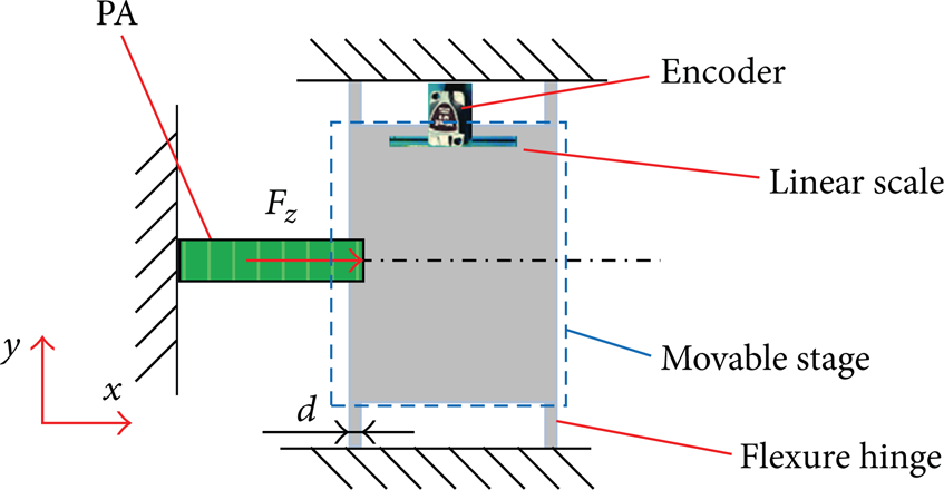
Piezoelectric actuator based flexure mechanism.
To simplify the complexity of the mechanism, the system's dynamics is modeled in terms of the lump mass discrete system as described in Figure 2. The PA can be regarded as a force generator which generates force as the voltage is applied. The dynamics of the PAFBM can be modeled by linear time-invariant second-order differential equations as follows:

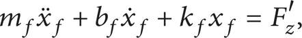
where F z is the force produced by the PA and F z ′ is the interaction force between the PA and the FBM; x z is the displacement of the PA as the voltage Vin is applied to the PA; x z is the displacement of the FBM due to the force F z ′; m z ,b z ,k z are the mass, damping, and stiffness coefficients for the PA; m f ,b f ,k f are the mass, damping, and stiffness coefficients for the FBM.

Lump mass discrete system for the PABFM.
Consider the PA and FBM are tight coupling and there is no relative displacement between them. Therefore, the mass centers of the PA and FBM have the same displacement (x f = x z ). As a result, the following equation can be deduced by adding (1) to (2):

where meq, beq, and keq are the equivalent mass, damping, and stiffness for this system, where meq = m z + m f , beq = b z + b f , and keq = k z + k f .
To obtain the parameters in the dynamic equation, the four flexures can be considered as the leaf springs between the stage and the ground. The leaf springs are thin, slender beams typically used as motion guides [24]. Using the coordinates in Figure 1, the designated dimensions are d along the x-axis, L along the y-axis, and h along the z-axis as shown in Figure 3.
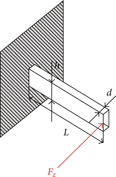
Leaf spring of the PABFM.
The nominal dimensions of leaf springs guiding the stage are h is 10 mm, d is 1 mm, and L is 6 mm. Leaf springs are usually manufactured with fillets at their ends with a small radius of 0.1 mm to reduce stress concentration. Basic elasticity theory can be applied to yield the bending equation describing the leaf spring deformation as follows:

where M b is the mending moment due to the force F z , E is the Young's modulus of elasticity, and I z is the moment of inertia about the z-axis of the beam. Based on the boundary conditions for the deflection, the stiffness of a single-leaf spring in the x-direction due to the force F z is as follows:
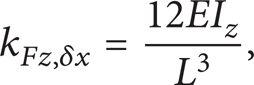
where E is the Young's modulus of A7075 (E = 7.2 × 10¹⁰ N/m2) and I z = hd3/12.
Therefore, we have

Assume these four-leaf springs are of the same thickness and they are working mechanically in parallel; the total stage stiffness is a sum of four-leaf spring stiffness as follows:

In addition, the stiffness factor of the PA can be obtained from the datasheet of PSt 150/5 × 5/20 as k z = 6 × 10⁷ (N/m). The estimated equivalent stiffness for this system is keq = k z + k f = 7.333 × 10⁷ (N/m). The equivalent mass of the system is about meq = m z + m f = 0.0044 + 0.067 = 0.0714 (kg) and the estimated equivalent damping coefficient of the system is almost zero.
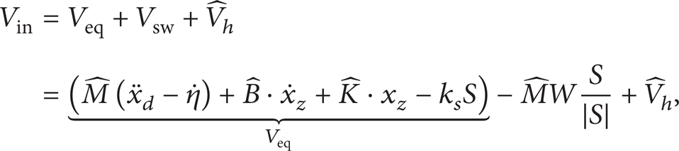
A piezoelectric stack actuator was chosen as the actuator for this flexural stage, because the piezoelectric stack actuators present many advantages, such as cost-effectiveness, little volume, high stiffness, very high response, and attainable displacements. The actuator used is PSt 150/5 × 5/20 piezoelectric stack from Piezomechanik GmbH. This actuator has the highest stiffness in comparison with other commercial products and provides a maximum nominal stroke of 20 μm and a maximum blocking force of 1600 N. The nominal stiffness of the actuator is 60 N/μm and the actuator that must be preloaded with is used to drive the stage. The output force F z is related to the voltage V z , but the relation between the actuated force and the voltage is nonlinear due to the hysteresis phenomena of PA. The schematic model, as shown in Figure 4, illustrates the three stages of transformation from electrical charge to mechanical energy, such as a voltage-charge stage, a piezoelectric stage, and a force-displacement stage. The dynamic equations of the mathematical model can be described as follows:

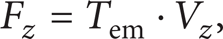

where F z and x z are the output force and the displacement of the PAFBM system as the voltage Vin is applied to the PA. Without considering the hysteresis (assume V h = 0), the output force F z is proportional to the voltage Vin based on an electromechanical transformation (EMT) ratio Tem. Besides the hysteresis, the displacement x z makes the capacitance of the PA produce charges q z via the same EMT ratio Tem. Consider the hysteresis phenomenon and the mechanical-electric transformation in (11); a counterelectromotive force (abbreviated CEMF) model for the PA is proposed in this research. The counter voltage of the PA is caused by the polarization and molecule friction for piezo materials and the hysteresis effect and this idea is similar to the counterelectromotive force for a motor caused by a changing electromagnetic field due to a rotating armature.
Electromechanical transformation model of the PABFM.
The CEMF of the PA that appears due to the voltage is applied. Therefore, the charge of the PA is influenced by two terms as follows; the first term q t is mainly caused by the polarization and molecule friction for piezo materials and the second term q x is caused by the electromechanical transformation due to the deformation. From (10)–(11), the following equation can be obtained:

Taking Laplace transform of (3), we have dedication

Then, substitute (13) into (12) and the equation can be derived as follows:

To obtain the CEMF voltage due to hysteresis phenomenon, the Duhem model is used to determine the CEMF feedback to the input as follows:

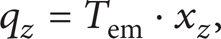
where α, β, γ are the parameters to determine the hysteretic loop's magnitude and shape. Due to the hysteresis effect, the hysteresis voltage V h can be considered as a counter EMF of the PEA caused by the polarization and molecule friction for piezo materials due to the input voltage. Figure 5 shows the proposed block diagram for the PAFBM with the proposed CEMF model; therefore, the dynamics model can be obtained as follows:

where Vin is the control voltage input and V h is the nonlinear effects and external disturbances due to the CEMF model. This nonlinear CEMF term, V h , can be obtained as follows:

where α, β, γ are the parameters to determine the hysteretic loop's magnitude and shape; Tem is the electromechanical transformation (EMT) ratio; C z = 1800 (nF) is the capacitance of the PA.

Counterelectromotive force (abbreviated CEMF) model for the PABFM.
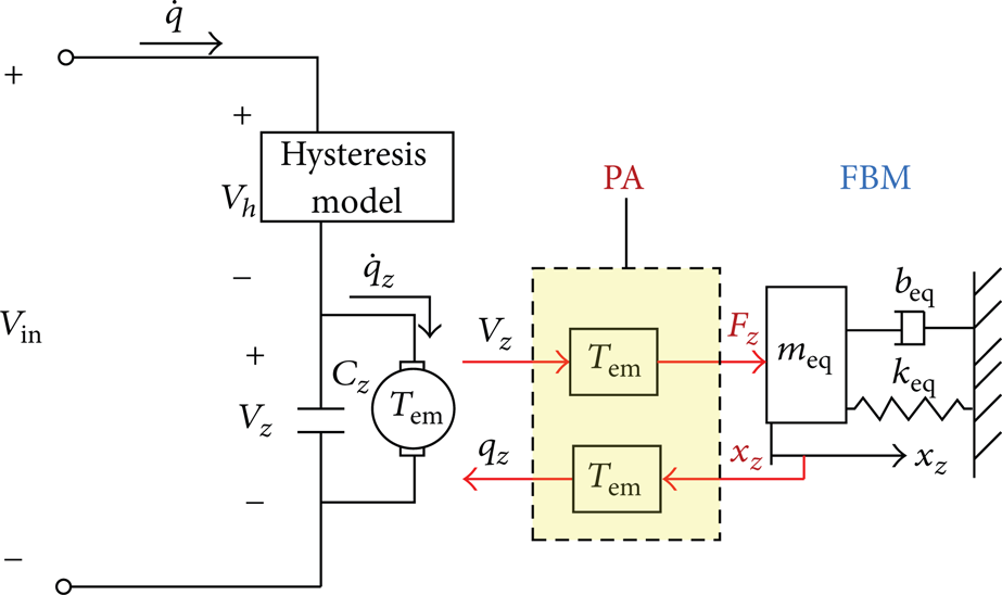
For control purposes, (16) is rearranged as follows:

where M = meq/Tem, B = beq/Tem and K = keq/Tem. In this study, a novel method is proposed to obtain a sliding-mode controller to solve the nonlinear disturbance term and make the system with robustness. With the given model in (18), an enhanced sliding-mode control with CEMF compensation for tracking control of this PAFBM is proposed and discussed in the following section.
3. Extended Sliding-Mode Control with CEMF Compensation
3.1. Extended Sliding-Mode Control Design
Sliding-mode control (SMC) can usually compensate tracking errors duo to the modeling uncertainties and external disturbance. However, the traditional sliding-mode control cannot attenuate mismatched disturbances effectively. In addition, traditional switching control laws are essentially discontinuous and chattering problem is unavoidable. For the PABFM system in this study, the nonlinear CEMF model (duo to the hysteresis) belongs to the mismatched disturbance for sliding-mode controllers. Therefore, using traditional sliding-mode controllers cannot effectively attenuate this nonlinear mismatched disturbance.
Many researches have discussed the nonlinear hysteresis effects for the frequency-dependent, rate-dependent, and charge-dependent phenomenon [15]. In our early study, the nonlinear hysteresis effects of the PA have been estimated and modeled using a generalized Duhem model [32]. Based on the aforementioned idea, assume the nonlinear CEMF model can be estimated by a dynamic system (a nonlinear observer) and then an extended sliding-mode controller with the CEMF model is proposed to attenuate the nonlinear disturbance effectively. To establish the control methodology using the sliding-mode control approach, a sliding surface for the existing method is defined as follows:

where e = x d − x z is the position tracking error and ξ is the state of a dynamic compensator used to shape the tracking errors. The dynamic compensator can be designed as follows:

where k v and k p are the designed gains which can be determined by the specified performance and α is a constant scalar such that α ≥ 0.
If the estimated nonlinear term obtained from the nonlinear CEMF model is denoted as
where Veq is the equivalent control of the sliding-mode control;
Substituting (20) and (21) into (18) yields

Define the modeling uncertainties as follows:

Substituting the above definitions into (22) yields

From (19) and substituting

Assume the switching control law Vsw can compensate the disturbance and uncertainties to make error states on the sliding surface and the closed-loop dynamics can be achieved as follows:

During the sliding motion where S = 0 and
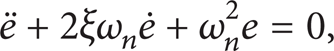
where ξ, ω n are the damping ratio and natural frequency of the 2nd order system, then, the parameters of the equivalent control law can be designed by choosing suitable η, k v , k p as follows:

With the proposed control methodology in (21), the PABFM system in (18) can be driven to reach the sliding mode.
Theorem 1. For the PABFM system described in (18) under modeled uncertainties ΔM,ΔB,ΔK and ΔV
h
=

and the term W is governed by

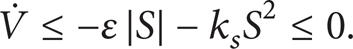
The parameters k s and ε in (29) and (30) are any positive scalars; the above necessary robustness condition can be proved as follows.
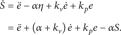
Proof. From (19) and (20), the time derivative of the switching function is determined as follows:
Define a Lyapunov function V(S) as follows:
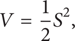
which is nonnegative and continuous. Differentiating V with respects to time yields
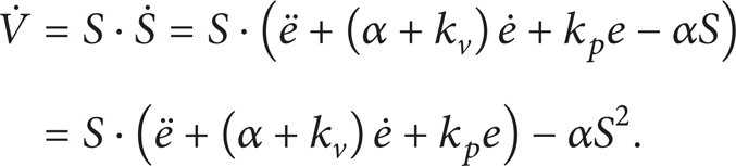
Substituting (25) into (33) yields

Substituting the term W in (30) into (34) yields
The above condition shows that V(S) → 0 as t → ∞ and this implies that the sliding motion is guaranteed. Therefore, the stability of the control system and convergence of tracking are guaranteed by using the proposed sliding-mode control law in (21) to make the closed-loop system follow the dynamic system of (27).
3.2. Formulation of the Optimization Problem to Identify the Parameters of the CEMF Model
To establish the estimated CEMF model and obtain the estimated hysteresis voltage

subject to

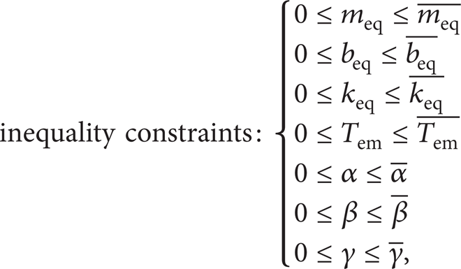
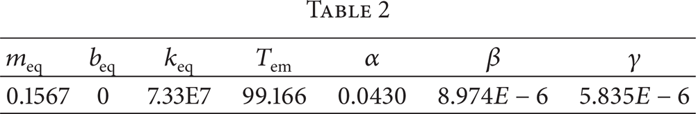
where J(x) is the objective function, x(i) represents the experimental value of the hysteric loop obtained via the measurement at the ith sampling time, x z (i) are the simulation using (36)–(38) at the ith sampling time, and N is the total sampling number from the experimental results. In this optimization problem, the objective function J(x) represents root mean squared errors (RMSE) between the experimental results and the simulation data. Therefore, the smaller objective function is that the identified parameters are more close to the actual parameters of the system. The charge system search (CSS) is used to solve this optimization in this research. CSS is a multiagent search approach proposed up by Kaveh and Talatahar in 2010 [33]. Because our early research has discussed how to solve the optimization problem, the procedures for solving this optimization are similar to the study in [32]. Therefore, the detailed procedures of solving the optimization are not discussed and omitted in this study. Table 1 shows the searching range for the PFBFM's system parameters in this study and Table 2 shows the identified results using the CSS based optimization.
The searching range for the parameters of the system.

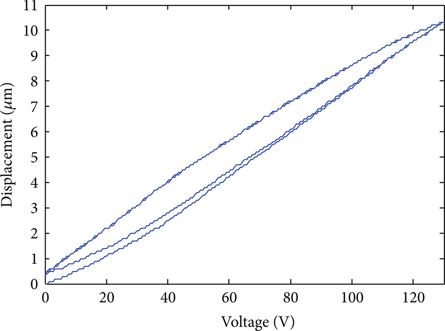
Hysteresis loop of the PABFM in this study.
4. Experimental Results and Discussion
Real-time experiments are carried out in two case studies to compare how the various sliding-mode controllers differ in responses. The PA of 20 μm-stoke (Model: PSt 150/5 × 5/20, Piezomechanik GmbH) is used to drive the stage and it is actuated by a PZT driver (voltage −20 to + 150 V; model CA45, CEDRAT, France). The position measurement system is based on a linear scale (with a resolution of 0.1 μm) incorporated with a linear encoder (Mercury 2000). The embedded DSP control system (dSPACE DS1104) is used as the motion controller of the ultraprecision positioning system. Real-time control codes are developed in Matlab Simulink and they are embedded in DS1104 controller. An experimental research facility has been established as shown in Figure 7 for investigating the proposed enhanced sliding-mode control. The experimental architecture is detailed in the block diagram as shown in Figure 8.
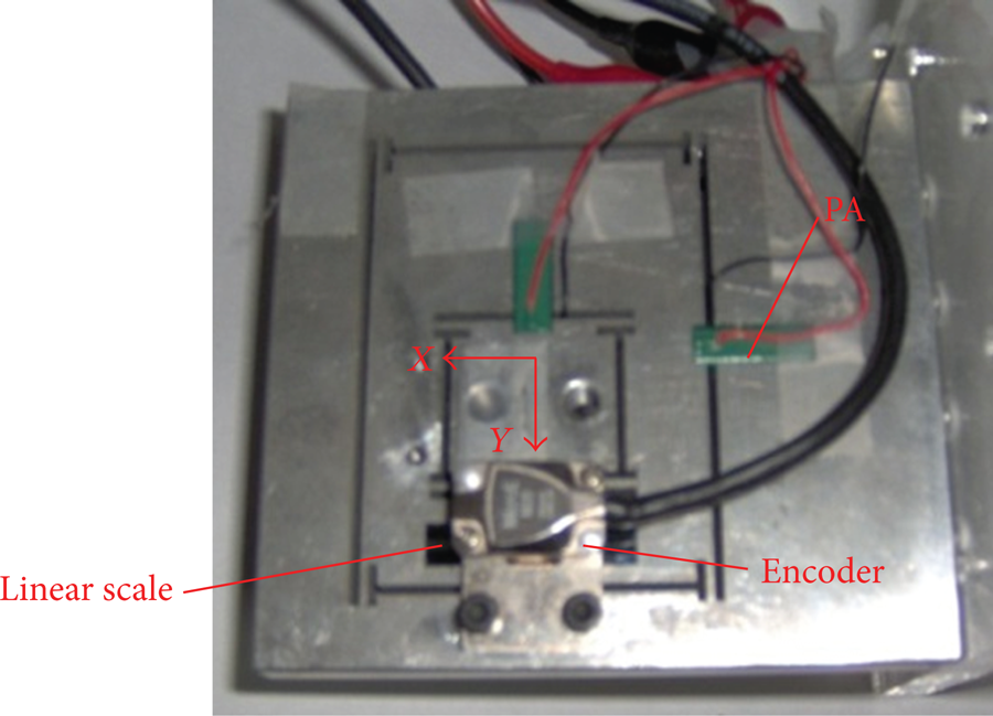
Experimental facility of the PABFM.

Block diagram of the experimental architecture.
Case 1. To control the PAFBM with the nonlinear hysteresis model, Case 1 is used to understand the performance of the proposed SMC without the CEMF compensation and Case 2 is used to understand the performance of the proposed SMC with the CEMF compensation. Therefore, in Case 1, the proposed sliding-mode controller without the CEMF term is used as follows:
First, the Simulink model of the PAFBM with the CEMF model is esTablished using the estimated parameters in Table 2. Then, the CSS method is used to search for the better parameters for the proposed sliding-mode controller via an optimization problem as follows:

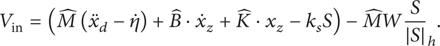
Second, the parameters obtained by the optimization are used for the controller's parameter for real-time implementation. To check the consistency between the simulation and the experimental results, Figures 9–11 show the comparisons between the experimental tracking results and the simulation results for the triangle signals at 5 Hz and 10 Hz. On one hand, the experimental results in Figure 9 show that the proposed sliding-mode control (see (39)) can deal with the nonlinear hysteresis, but the small tracking errors exist due to the mismatched disturbance. Figure 10 shows that the effect of mismatched disturbance is more clear as the tracking reference is faster. On the other hand, Figures 9 and 10 show that the simulation error is very similar to the experimental error without considers the white noise. This means that the identification of the CEMF model is very effective. Figure 11 also shows that the proposed controller can track the sinusoidal signal (5 Hz) but not so precisely.
(a) Tracking error and response for experimental results and simulation using the proposed SMC, (b) room-in plot in the time interval of 0.2~0.4 (second).

(a) Tracking error and response of the triangular signal at 10 Hz for experimental results and simulation using the proposed SMC, (b) room-in plot in the time interval of 0.2~0.3 (second).

(a) Tracking error and response of the sinusoidal signal at 5 Hz for experimental results and simulation using the proposed SMC, (b) room-in plot in the time interval of 0.2~0.4 (second).
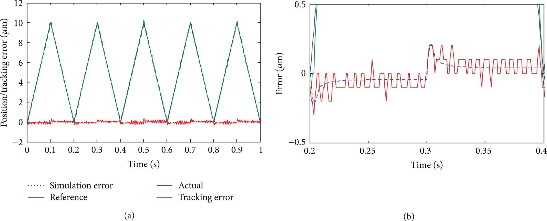
Case 2. To improve the performance of the proposed SMC, the proposed SMC with the CEMF feedback is used in Case 2, Figures 12–13 show the experimental results for tracking the same triangle and sinusoidal signals as the same as Case 1 for comparison. In Figures 12–13, the experimental results validate the effect of the CEMF feedback. For the task to track the 5 Hz triangle signal, the root mean square error (RMSE) is reduced from 0.1118 to 0.0715 (μm). For the tracking task of the 5 Hz sinusoidal signal, the RMSE is reduced from 0.1007 to 0.0539 (μm). Figure 14 compares the tracking error of the open-loop and the proposed SMC from the SMC + CEMF for the 5 Hz triangle signal. Table 3 summarizes the RMSE of experimental results for the proposed SMC + CEMF, SMC, and open-loop. Experimental results validated the effectiveness of the proposed approach.
The RMSE of the proposed method with uniaxial actuated base on x-axis.


Tracking error and response for experimental results using the proposed SMC + CEMF (triangular signal at 5 Hz).

Tracking error and response for experimental results using the proposed SMC + CEMF (sinusoidal signal at 5 Hz).
Comparison between the tracking error for the open-loop controller, SMC, and the proposed SMC + CEMF (sinusoidal signal at 5 Hz).
5. Conclusions
A piezoelectric actuator is utilized herein to actuate a flexure mechanism stage to perform precision tracking tasks. To compensate for the tracking error of the PABFM that is caused by nonlinear hysteresis, the dynamics of the nonlinear hysteresis are modeled by the hysteresis CEMF model. The CSS method was used to evaluate the parameters of the nonlinear hysteresis CEMF model via the optimization problem. In addition to performing ultraprecision tracking task, the proposed SMC with the CEMF compensation improves the tracking response under external disturbances. To establish the consistency of the simulation and real-time experimental results, the proposed controller is implemented in real time using the dSPACE DSP in two case studies. The experimental results thus verified the effectiveness of the proposed controller.
Conflict of Interests
The authors declare that there is no conflict of interests regarding the publication of this paper.
Footnotes
Acknowledgment
The authors would like to thank the National Science Council of the Republic of China, Taiwan, for financially supporting this research under Contracts nos. NSC 102-2221-E-027-040-MY2, NSC 101-2221-E-027-029, and NSC 102-2221-E-027-024.