
Abstract
Cryptographic key management for wireless sensor networks (WSNs) and mobile ad-hoc networks (MANETs) is a particularly challenging task, as they mostly consist of high counts of resource constrained nodes, especially when group communication and dynamic network membership capabilities are required. The logical key hierarchy (LKH) is a well-known class of protocols which aims to solve the key management problem and minimize rekeying overhead, using hierarchical structures and taking advantage of multicast communication. In this work we propose a method for obtaining LKH structures by taking into account the topology of the underlying network, leading to a further decrease in rekeying costs, in terms of packet transmissions.
1. Introduction
Security is an essential element for any application of wireless networks. Its application in WSNs and MANETs is hindered by additional challenges and requirements which arise from their large scale and resource constrained nature. Key management, in particular, is one of the security aspects which requires a totally different approach from conventional networks.
Key management [1] refers to the procedures which support key establishment and the maintenance of ongoing keying relationships (replacing, canceling keys, etc.) between the network's nodes; it is an essential part of the security procedures of wireless networks. Several key management schemes exist, which support different communication flows and either dynamic or static networks.
Nowadays, in high-end device networks, there is a clear prevalence of public key algorithms, regarding key management functions. The most characteristic example is TLS [2] (and its predecessor, SSL [3]), used, among other applications, in the HTTPS protocol [4]. These networks and applications, however, are largely different from MANETs and WSNs, regarding node capabilities, node count, and traffic flow.
This gave rise to the development of key management protocols specifically designed for low resource, high node number wireless networks. Both private and public key based schemes were developed, each focused on particular features and aspects for optimization. Symmetric schemes [5] impose a generally lower computational and network overhead but need at least predistributed keys, and symmetric keys must not be compromised (or a suitable key revocation scheme needs to exist for such occasions). Conversely, in asymmetric schemes [5], no secret keys need to be distributed, and the main issues are the authenticity of the public keys, which must either be established by a certificate authority (CA) or by public key predistribution and the high computational overhead of the public key algorithms.
One key aspect that needs to be considered for key management schemes for MANETs and WSNs is group communication [6]. In MANETs particularly, there is a need for any network node to be able to communicate with any other node. Several prominent key management schemes, such as base station participation [7], polynomial [8], probabilistic [9], and their modern variations, such as [10], do not use a network-wide traffic encryption key (TEK). Thus, group communication using these schemes is impossible or impractical, as capability for communication between any two nodes is not guaranteed.
While not every application uses a group communication model for its core function, a substantial number of applications can benefit from data aggregation, as shown in [11–13]. However, the use of data aggregation requires the ability of nodes to communicate directly with several nodes other than the final recipient(s) of their data. In this case, a key management scheme that supports group communication should be considered. An oversimplified implementation of data aggregation can be established, where data is left as originally encrypted at the source until reception at the destination. However, although this does not necessitate the need for group communication, the additional overhead required per data-sent defeats the purpose of using aggregation.
Another key issue for MANET/WSN key management is scalability. As these types of networks can scale up to hundreds or thousands of nodes, the key management schemes must still be able to function efficiently. When coupled with a demand for the aforementioned group communication, which makes use of a network-wide secret key, inherently detrimental to scalability, several key management schemes ([7–9], as well as possible modifications which could add a network-wide key) proposed in the literature are rendered unsuitable.
One class of key management schemes which is scalable and also supports dynamic networks and group communication is the one based on the LKH [14]. The base concept was introduced by Wong et al. in [14, 15] and independently by Wallner et al. in [16]. Variations and adaptations of the main technique to mobile networks have appeared in [17–20] and others.
Most of these schemes generally have been mostly examined in theoretical single hop scenarios; however multihop network topologies and the relevant communication cost have not been considered. There are works that examine the structuring of networks, but without taking multihop communication into account: the optimal theoretical (single-hop) LKH structure in terms of number of messages is discussed by Lee et al. in [21], while finding computation-wise optimal key structures is presented by Zhu in [22]. In some works, multicast topology is taken into account in the formation of the hierarchies: the creation of location-aware structures is discussed in [17], where the formation is achieved by clustering the nodes, using their (assumed known) position. In [23], a topology-matchingkey management tree scheme is presented and is targeted at networks with an inherent hierarchy, which does not fit the profile of ad-hoc networks. In [24], a topological key hierarchy (TKH) approach is presented, in which key hierarchies are constructed based on their connection graph. Results presented show better performance than several LKH-class techniques. However, TKH is only compared to techniques that use randomly-picked structures and thus do not utilize the performance potential of LKH.
In this work we present a set of methods to form LKH structures for a multihop network, given its connection graph. The main characteristic which we seek to optimize is the number of packet transmissions needed for rekeying operations. More specifically we seek to optimize the mean and maximum number of packet transmissions for kick node operations in the LKH scheme. The methods that we propose include the selection of a Key-Server, the derivation of an initial hierarchical structure, based on the network topology, and, finally, a set of local optimization criteria, which improve the performance of the initial hierarchy.
The rest of the paper is organized as follows. In Section 2 a brief overview of the LKH scheme is presented. Section 3 presents an overview of TALK. The network and security assumptions we have made in this work are given in Section 4. In Section 5 we present methods to create preliminary LKH structures for a given network and Key-Server. In Section 6 we give a method to select a Key-Server which leads to minimal rekeying overhead. Procedures to optimize preliminary LKH tree structures taking into account the network topology are given in Section 7. Section 8 contains additional protocols and procedures needed for an actual implementation of our method on a real network. In Section 9 the application of our method is presented in detail for an example network. In Section 10 simulation results are presented on the performance of our method and protocols, and finally, in Section 11 we draw our conclusions.
2. Secure Communications with Logical Key Hierarchy (LKH)
Several classes of network applications use group communication [6], where in order to achieve secure group communication when symmetric ciphers are considered, a TEK generally needs to be shared among members of the group. Alternative approaches such as probabilistic key distribution can be applied, but at a cost, introducing overhead for communication between nodes that do not share keys.
When the group membership changes, the TEK needs to be refreshed, where (a) in the case of a node joining the network and/or periodic key refreshing, the rekeying operation can be performed by simply multicasting the new key to the whole network, and (b) when a node departs (or needs to be kicked), the new key needs to be distributed to the network in a way that the departing node cannot capture it. LKH [16] solves this problem by laying out the network nodes as the leaves in a tree structure (Figure 1).
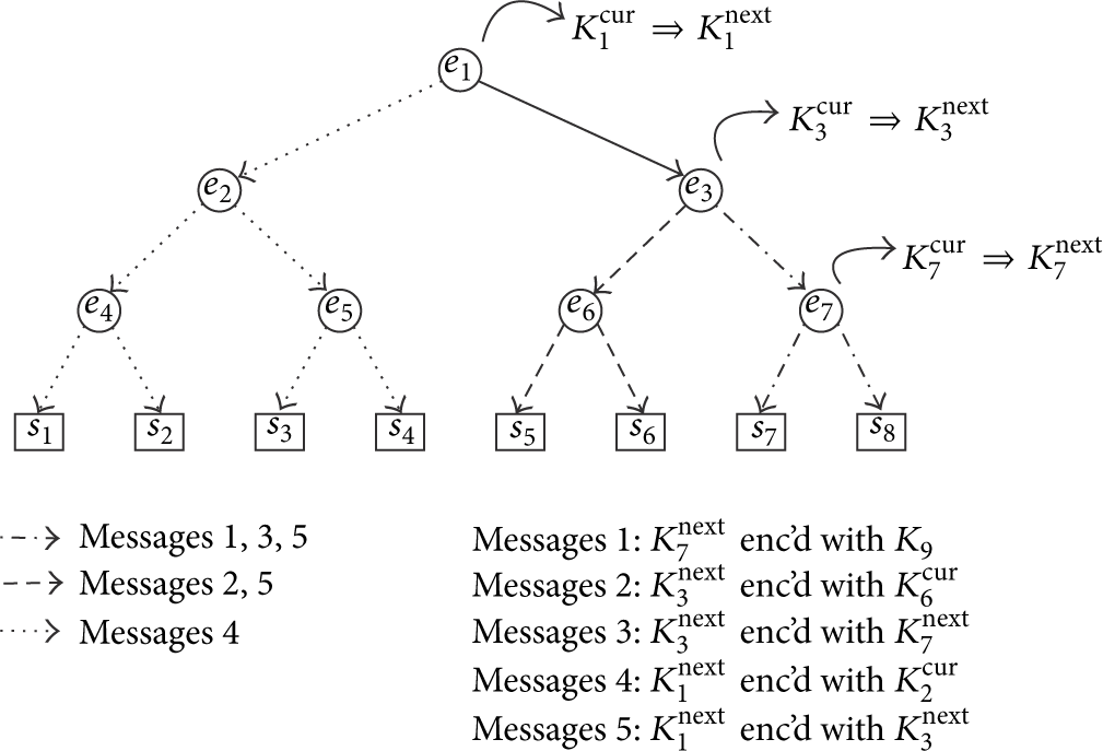
Logical key hierarchy—node kick example.
Each internal node i is then associated with a key encryption key (KEK)
When a node needs to leave the network, all keys corresponding to its path to the root node in the key tree must be renewed, according to the following set of bottom-up operations.
The leaving node is removed from the tree. For each internal node in the path from the node to the root, a message is sent to each subcluster i, corresponding to one of its children, encrypted with the corresponding KEK If the subcluster is a single leaf j, then the pairwise key
For example, consider an 8-node network, laid out in a tree (Figure 1). To kick node

3. Overview of TALK (Topology Aware LKH Key Management)
This work presents a set of algorithms and protocols that aim to calculate a suitable Key-Server and LKH trees for a network, which reduces the traffic incurred on the network, when rekeying is needed.
The main metric which we seek to minimize is the total number of packets transmitted over the network. As previously mentioned, there are two main operations involved in LKH-based key management: (a) the node join operation and (b) the node kick operation. Since (a) is performed using a single broadcast from the Key-Server, we focus on (b) which is a much more overhead incurring operation.
TALK is logically separated into two parts: The Key-Server selection and the key tree formation. The first part is executed on network bootstrap and optionally repeated over large intervals, when massive topology changes take place or the Key-Server functionality has to be handed over to another node (e.g., low energy on the current Key-Server). The second part, the key tree formation, is also executed when a new Key-Server is selected, but it is a simpler procedure that can be executed more often, when the gains in rekeying traffic outweigh the structure change overhead. Local tree optimizations are also defined, opportunities for which can be found and applied without global network topology knowledge.
4. Network and Security Assumptions
In this work we assume the nodes of the network are capable of both unicast and broadcast communication. No routing information is assumed to be known or needed.
An uncompromisable Key Master Server is assumed, which has the capability for secure pairwise communication with all network nodes at network bootstrap. We assume that adversaries can eavesdrop all communication. Also, any number of nodes can be captured and their known secrets made known to adversaries, although detection of such an intrusion is outside the scope of this work. We do not consider Denial of Service attacks, that prevent nodes from receiving any legitimate network packets, but packet loss occurring due to traffic congestion is taken into account and is present in our simulations.
5. Initial Formation of the Key Tree
Our approach for the creation of LKH key trees is based on topological tree representations of the network, which we call topological network trees (TNTs). It is used for finding out the optimal node to function as a Key-Server and also as a basis for the final version of the key tree. It is extracted from the connectivity graph of the network and a selected root node, in a shortest hop count fashion.
The TNT is created (Algorithm 1) in a number of rounds equal to the maximum hop distance from the root. The set
temp = temp += Break
From the TNT we extract a topological key tree (TKT) using the following recursive algorithm, which creates a topological key subtree (TKsubT) corresponding to a branch in the TNT, rooted at the current node. (1) For the current node, check if it is an intermediate node in the TNT.
root = new LogicalNode tmp = copy (cnode) root.attachchild (tmp) tmp = makeTKsubT (ch) root.attachchild (tmp) root = copy (cnode)
6. Key-Server Selection
An important step in defining the LKH structures for a given network and topology is the selection of a node that will function as a Key-Server. Depending on the application and node capabilities, this can be predefined and can not be possible or impractical to change (due to the advanced computing capabilities that this node should have in order to accommodate the key management overhead). For the cases where a Key-Server has to be selected among the nodes of the network, it is essential to pick the one which results in small rekeying overhead. This procedure is executed at network deployment time, when initial node positions are established. As it is relatively resource intensive, it is repeated only when needed, as when the current Key-Server is running low on battery or when the network topology has changed so much that it is inefficient to keep the current Key-Server.
We propose two multicriteria selection methods for the Key-Server. (a) The first uses extended network topology information, found in the TNTs of the network and primarily involves calculations of kick node procedures, and (b) the second one involves only the less demanding criteria of the former.
The criteria employed in our approaches are the following:
maximum distance from network nodes; sum of distances from network nodes; mean kick node packet cost using the TNT; maximum kick node packet cost using the TNT.
For a specific Key-Server candidate, the TNT is first extracted, followed by calculations for kicking all possible nodes and the mean value is kept; these rekeying operation cost calculations would normally be performed on the TKT, but as at this point the two trees are equivalent, so we perform the calculations on the TNT directly.
A topology matrix T is extracted from the TNT to facilitate easy rekeying overhead calculations. Each element in T is the number of children of a particular node. Each row corresponds to the same level of nodes in the TNT. Using zero-based indexing, the element (0,0) corresponds to the root node. The number of rows in the matrix is equal to the depth of the TNT, while the number of columns used is different for each row, the maximum being equal to the maximum number of nodes in a TNT level, which is at most the number of network nodes minus the root node (star topology). A topology matrix example is shown in Figure 2(b), corresponding to the TNT in Figure 2(a). Unused elements (shown as “N” in Figure 2(b)) can also be stored as zeroes, without affecting the behavior of T.

Example TNT and topology matrix.
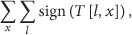
Using this network topology representation, we can calculate the number of packet transmissions needed in order to kick a specific node from the network. The number of packets needed for multicast to the whole network is the number of nonzero, nonunused elements in T:


The number of packets

6.1. Number of Packets for Node-“Kicking”
In order to compute the number of packets needed to kick node

6.2. Maximum Distance from Network Nodes
The Key-Server should not distanced from the far nodes of the network, since this will involve the transmission of signals with a large number of hops. Hence, for each node

6.3. Sum of Distances from Network Nodes
In order to capture the need on a median-basis for the Key-Server to communicate with all nodes, there is a need to transmit messages to each node, and henceforth the sum of hop-counts from the candidate

6.4. Extended Key-Server Selection Method
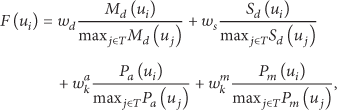
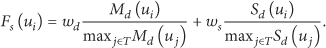
For the Key-Server node-selection, we calculate for each Key-Server candidate
A fitness values is formed for each Key-Server candidate
6.5. Simplified Key-Server Selection Method
In addition to our main Key-Server selection method, we proposed a simplified version, which can be used in situations where a very calculation overhead is of high importance. In this version, the more computationally demanding factors,
7. Optimization of the Key Tree
Once the Key-Server is selected and the TKT is created, we seek to optimize it with regard to the packets needed for rekeying. Local optimizations are applied, which are easily calculated and implemented in actual networks, where global network knowledge is difficult to achieve. In addition to the TKT construction time, these optimizations can be performed periodically or on opportunity detection.
In order to accomplish this task, we remove superfluous logical nodes (LNs) while at the same time, we create additional LNs in segments with many children.
7.1. Removal of Superfluous Logical Nodes
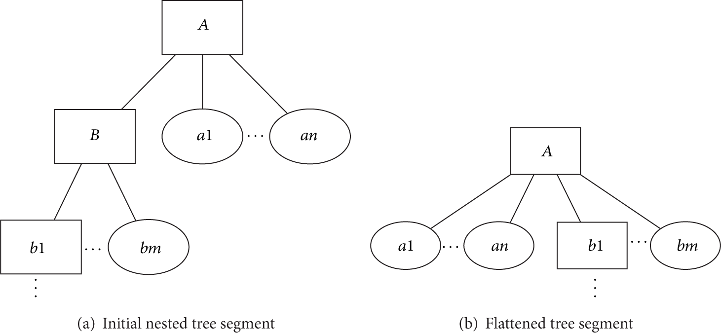
Depending on the structure of the underlying network, some parts of the TKT might be deeply nested, with a small number of leaves, which leads to an increased rekeying overhead. Our local optimization algorithm looks for nodes with one logical child and few real children and optimizes their logical child out, as in Figure 3. Specifically, the optimization is applied when a logical node is found with no more than one logical and one real child. It should be noted that the TKT creation algorithm does not produce LNs with only one logical child or one real child, but such nodes are possible, especially when considering membership changes during run-time.
Superfluous LN removal.
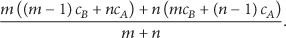
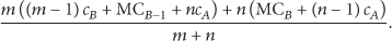
Regarding the rekeying cost in such key segments, let us consider a nested structure like in Figure 3(a), where there is a LN A with n RN children and a LN child B, which in turn has m RN descendants (not necessarily direct descendants). Let the mean cost in number of transmissions for a packet from the Key-Server to reach one of of A's children be


Rule #1. When there is one LN-A in the key tree which has one LN-child-B and one RN-child, it is always preferable to remove B from the tree and attach its descendants to A.
7.2. Creation of Additional Logical Nodes
Complementary to the optimization of over-nested parts of the key tree, there can also exist flat tree segments, which increase the rekeying cost in a linear relationship to the network size. Our optimization algorithm creates additional hierarchy to reduce the rekeying packet transmissions. Specifically it looks for LNs with multiple RN-children and at least one LN-child and subsequently creates a new LN-child and nests the RN-children under it, as shown in Figure 4.

Addition of new LNs.
The initial form of the considered tree segment (Figure 4(a)) is the same as in Section 7.1, with the rekeying cost described in (12):


Rule #2. When there is one LN with multiple RN-children and at least one LN-child, then create a new LN-child and nest the RN-children under it, if (20) is satisfied.
Since the knowledge of the network's topology for validating (20) is immense, an over-conservative variation of the previous Rule #2 can be employed by switching (22) with (20).
8. Adaptation and Additional Protocols for Implementation on a Sensor Network
The procedures described above require an extensive knowledge of the network topology, in order to function. Specifically, in order for every node to calculate its fitness value as a Key-Server, four (two) factors need to be calculated for the extended (simplified) Key-Server selection method. We focus on the extended version, the requirements of which are a superset of those of the simplified method.
To calculate its fitness value, each node
This information is gained via a flooding of the routing information; once the aforementioned parameters are calculated, the evaluation of (11) requires the computation of the terms flooding of routing information; calculation of flooding of the previously calculated parameters and computation of their maximum values over all network's nodes; calculation of fitness values at each node; flooding of the fitness values and selection of the minimum fitness value along with the respective node identification; calculation of the optimized TKT at the selected Key-Server node.
In the sequel, we provide a detailed description of each step.
8.1. Flooding of Routing Information
The goal of this step is for all nodes to acquire a tree representation of the network, rooted on themselves. It is assumed that initially all nodes have no information on the network topology. At the beginning, all nodes start broadcasting the routing information that they currently hold.
The structure of the packets being broadcast from a node is a chain of nodes stemming at each node; this corresponds to a topological chain, (i.e., node k in the chain is a neighbor with nodes
In our prototype implementation, target nodes are selected by selecting a random node (among the known ones) and then recursively picking random descendants until a network-leaf has been found. This leaf is selected as a target node. The use of leaves as target nodes aims to exploit available packet space, in order to broadcast more routing information in a single packet.
The structures used for storage of routing information contain (a) the node's identification number, (b) the number of hops needed to reach it, (c) a link to its parent, and (d) links to its children. When a routing packet is received at a node, the node checks if the packet contains new and/or more efficient routing paths, compared to the ones already known. The checking starts at the first element in the packet, that is, the node which actually broadcast the packet. Two checks are made for each element
If
If
This procedure is equivalent to the one described in Section 5. One difference is that the former picks lexicographically first parents, when there are multiple options for the placement of a node, while this one favors the one that was found first, in order to minimize changes in the topology.
8.2. Calculation of Fitness Function Factors
,
,
, and
at Each Node
This step contains most of the calculations mentioned in Section 6. Since a TNT exists in each node, the noted parameters in the fitness equation (10) can be calculated at the respective nodes using the aforementioned procedure.
8.3. Flooding of
Values
This step aims to make the
8.4. Calculation of Fitness Values
at Each Node
After a large interval, all needed values in (10) are known at each node, and its fitness value can be locally calculated.
8.5. Flooding of
and Node Identification
At this time, each node holds its own fitness value, and these values are broadcast in order for all nodes to acknowledge the one with the minimum value. In a procedure similar to the step of Section 8.3, the pair of (a)
8.6. Calculation of Optimized TKT at the Selected Key-Server Node
At this time, the new Key-Server is chosen and can calculate the optimized key tree, as described in Section 7. Finally, keys must be generated for each key tree node and transmitted to the appropriate nodes.
9. LKH Application Example
As an application example, assume the 20 node network of Figure 5, in which we need to use LKH. We focus on the algorithmic procedure, assuming centralized and complete network knowledge.

Example network.
9.1. Selection of the Key-Server
To create an LKH structure for the given network, it must first be decided which node will function as the Key-Server. To that end, the procedure described in Section 6 is followed. The criteria used for the selection of the Key-Server are the maximum distance (equation (8)), the sum of distances (equation (9)) from the rest of the nodes, and the mean and maximum of packet transmissions for a kick operation, when using the corresponding TKT (7). The selected weight parameters were
Parameter values used in Key-Server selection.

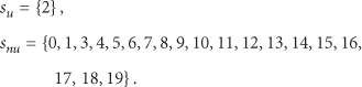
The node with identification index number 2 minimizes the fitness function (10) and is selected to function as a Key-Server for the network.
9.2. Initial Formation of the Key Tree
As soon as the Key-Server has been selected, the rest of the key tree can be formed. The step of the initial formation of the tree is performed first (this procedure is actually performed at the selection of the Key-Server for all candidates, but it is presented here only for the actual chosen Key-Server, for conciseness and clarity).
As described in Section 5, using the selected root node (Key-Server) and connection graph, a TNT is extracted, shown in Figure 7(a). The operation of our tree creation algorithm is as follows.
Initially,
Nodes in The current tree is shown in Figure 6(a). Nodes in The current tree is shown in Figure 6(b). The nodes that are adjacent to the ones in The current tree is shown in Figure 6(c). The remaining nodes, 8 and 16, are added to the tree as children of 13. The resulting TNT is shown in Figure 7(a).


Intermediate trees of the example network.

Initial trees of the example network.
The TKT is then extracted from the TNT using Algorithm 2. Essentially, for each non-leaf RN (excluding the root node), a LN is created and positioned in its place in the tree, and the RN is attached as a child of the newly created LN.
Specifically in our example, the nodes 0, 1, 6, 7, 13, and 14 are such internal RNs. LNs L0, L1, L6, L7, L13, and L14 are created and take the place in the tree, which are then attached beneath the latter. The resulting TKT is shown in Figure 7(b).
9.3. Optimization of the Key Tree
After the TKT-formation, its optimization takes place, based on the following steps.
The TKT is searched for superfluous LNs (LNs with no more than 1 LN and 1 RN child). In our example, the only superfluous LN is L1 (its children are 1 and L13). As such, it is removed and its children are attached to its parent, L6. The result is shown in Figure 8(a). The tree is searched for segments where additional nodes should be created (LNs with at least one LN child and multiple RN children). The first such node found is L2, which has the LN children L6 and L7 and the RN children 2 and 12. A new LN LMC2 is created under L2, and 2 and 12 are nested under it, as shown in Figure 8(b). The next candidate segment for additional LNs is the one under L6, which has 1 LN child and 5 RN children. The new LN LMC6 is created under L6, and the 5 RN children are nested under it, as shown in Figure 8(c). The last candidate segment for additional LNs is the one under L7, which has 2 LN children and 4 RN children. The new LN LMC7 is created under L7, and the 4 RN children are nested under it, as shown in Figure 8(d).

Optimizations of the key tree.
Simulations were performed for the previous four optimization steps of the process, measuring the mean and maximum number of packets required for rekeying. The results are shown in Table 2.
Simulation results for the example network.

10. Simulation Studies
In order to evaluate our key tree generation method performance, we implemented our algorithms and protocols on top of the Contiki OS [25] and ran simulations on the Cooja Network Simulator [26]. The nodes of the networks were TelosB nodes [27], emulated using MSPSim [28], an instruction-level simulator for Texas Instruments' MSP430 based systems.
For the purposes of our measurements, the network nodes were roughly synchronized, and the same predefined time periods were given for each calculation and communication step. The measurements taken were the actual time needed for each step, (a) the output of each factor of the fitness function and (b) the final result for each node.
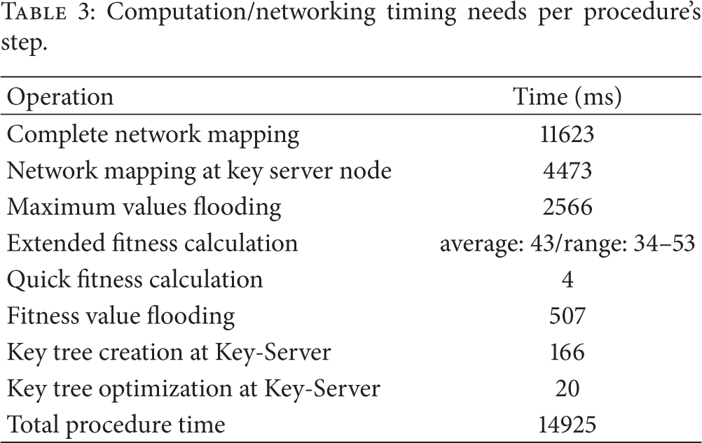
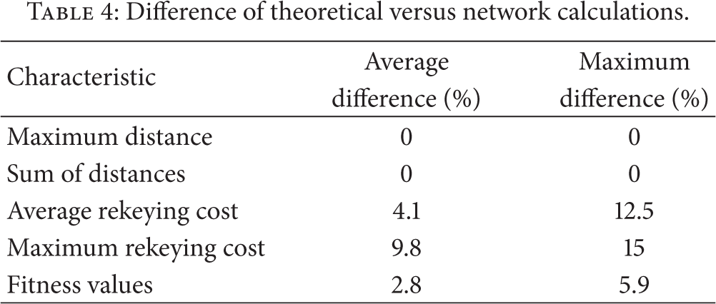
In the sequel, we present the results produced for the network used in Section 9, shown in Figure 5. Time results are shown in Table 3. Table 4 shows the difference in calculated results versus the theoretical results, which is due to the topology information being acquired from the actual network, subject to limited bandwidth, collisions, and limited time.
Computation/networking timing needs per procedure's step.
Difference of theoretical versus network calculations.
As shown in Table 3, the entire procedure needs, for our network, less than 15 seconds, which is quite reasonable, taking into account that it will only be run at network bootstrap and possibly few times at runtime, when deemed necessary by severe topology changes, having a negative impact on rekeying performance.
If we assume that the network topology changes can be detected, it is relatively easy to calculate the current rekeying performance and evaluate the gain of modifying the key tree structure to improve the latter. It should be noted that that the combined fitness calculation, key tree creation, and optimization need a mere 229 ms (
Examining Table 4, we can observe the difference of theoretical and simulated results. The maximum distance and sum of distances factors are exactly the same for both cases. These factors depend on the initial key tree creation procedure, described in Section 5, and its adaptation for the networked-version, described in Section 8. The centralized theoretical version is designed to connect nodes to the root using minimum hop-distances, resulting in minimum results for these factors. The simulated results are exactly the same, meaning that the route network discovery protocol also yields minimum hop-distance connections.
Associating the rekeying cost into a network load context, as shown in [29], a packet rate of up to 12.8 packets/second at the Key-Server could be used before the appearance of packet loss. The rekeying process will take a time proportionate to the number of unique rekeying messages created and sent by the Key-Server. With the selected (optimal) Key-Server in our example network, the number of unique messages can reach 14, before optimizations and 9 after optimizations. This translates to 1.09 and 0.7 seconds, accordingly, needed for the rekeying procedure. However, when a nonoptimal Key-Server is chosen, the number of unique messages jumps to 24 and the time to 1.875 seconds accordingly.
Regarding the rekeying cost metrics, we observe some difference between theoretical and simulation values, which is is due to a subtle difference in their key creation algorithm. In the centralized theoretical model, we choose the lexicographically first option, when there are multiple possible parents for a specific node. In the network version, however, we keep the firstly discovered parent, when a newly found one does not reduce the node distance, aiming to minimize changes in stored topologies. These differences however do not have a great impact on the calculated fitness value, the difference averaging at 2.8% between theoretical and simulation results.
11. Conclusions
In this work we presented a novel method to apply logical key hierarchy class key management to multihop networks, using knowledge of the network topology in order to reduce rekeying overhead. A multicriterion approach of selecting the Key-Server is presented followed by a method for defining an LKH structure using the connection graph of the network and the selected Key-Server node, which is comprised of an initial tree formation step and subsequent tree optimization steps. Due to the simplicity of the recalled procedures, the presented methods presented can easily be implemented on actual low resource MANETs and optimization can also be done at runtime, providing low cost key management for such networks.
Footnotes
Glossary
Conflict of Interests
The authors declare that there is no conflict of interests regarding the publication of this paper.
Acknowledgments
This research has been cofinanced by the European Union (European Social Fund (ESF)) and Greek National Funds through the Operational Program “Education and Lifelong Learning” of the National Strategic Reference Framework (NSRF), Research Funding Program: Thalis-AUEB-DISFER.