
Abstract
Structured-light three-dimensional (3D) vision measurement is currently one of the most common approaches to obtain 3D surface data. However, the existing structured-light scanning measurement systems are primarily constructed on the basis of single sensor, which inevitably generates three obvious problems: limited measurement range, blind measurement area, and low scanning efficiency. To solve these problems, we developed a novel 3D wide FOV scanning measurement system which adopted two multiline structured-light sensors. Each sensor is composed of a digital CCD camera and three line-structured-light projectors. During the measurement process, the measured object is scanned by the two sensors from two different angles at a certain speed. Consequently, the measurement range is expanded and the blind measurement area is reduced. More importantly, since six light stripes are simultaneously projected on the object surface, the scanning efficiency is greatly improved. The Multiline Structured-light Sensors Scanning Measurement System (MSSS) is calibrated on site by a 2D pattern. The experimental results show that the RMS errors of the system for calibration and measurement are less than 0.092 mm and 0.168 mm, respectively, which proves that the MSSS is applicable for obtaining 3D object surface with high efficiency and accuracy.
1. Introduction
Structured-light 3D vision measurement is becoming increasingly important owing to its noncontact, high precision, and good system flexibility. A basic structured-light sensor is usually composed of one camera and one laser projector together forming an active stereo pair. The laser projector projects a light plane onto an object. When the light plane reaches the target surface, it forms a distorted stripe of illuminated points due to the irregular surface. Then the camera records the illuminated target. If the sensor is properly calibrated, the 3D coordinates of the illuminated points can be calculated by the well-known triangulation method.
According to the number of structured-light sensors, the existing structured-light 3D surface capturing system can be currently classified into two categories. One is single structured-light 3D surface capturing system which means that it contains only one structured-light sensor and projects a single light stripe on the object surface. This kind of system is easy to implement due to its simple structure, but its major defects are quite obvious: measurement range is limited and there are blind measurement areas for complicated objects. As a result, the single structured-light 3D surface capturing system is only applied to measure objects with simple structure and no hiding surface [1–4]. The other category is the double structured-light 3D surface capturing system, which is composed of two structured-light sensors. For such a system, the measured object is scanned from two different angels, so the measurement range is expanded and the dead zone is reduced relatively. However, the scanning efficiency of the double structured-light 3D surface capturing system is low, because the number of light stripes is small and it only covers a small area on the object surface.
Some vision measurement systems based on structured-light have already been successfully applied to industrial inspection. For example, Alippi et al. developed a detection system for track profiles of railways based on laser scanning and image analysis [5]; Loh and Lu presented a solder joint inspection system using structured-light [6]; Haug and Pritschow proposed a robust laser-stripe sensor system for automated weld-seam-tracking in shipbuilding industry [7].
All the preceding inspection systems have a common point that they are all constructed on the basis of a single structured light sensor, as single structured-light system is low cost and easy to implement due to the simple structure. However, if the single structured-light sensor is adopted in the 3D surface measurement system, three obvious problems are inevitable: limited measurement range, blind measurement area, and low scanning efficiency. As a result, the single structured-light 3D surface measurement system is only applicable to the object with simple structure and no hidden surface [8].
Aiming at overcoming these problems, we design a 3D wide FOV scanning measurement system, which adopts two multiline structured-light sensors to construct the system. Each sensor is composed of one digital CCD camera and three line-structured-light projectors. While the object is moving at a certain speed, the system projects six parallel light stripes onto the object surface and scans from the two sides of the measured object. Therefore the FOV and measurement range had been expanded, dead zone is effectively reduced, and, most importantly, the scanning efficiency is greatly improved.
To design and use a MSSS system, three main aspects need to be made efforts on: the measurement model, the extraction and arrangement of light stripes, and system calibration.
Firstly, establishing a reasonable measurement model is the first requirement to construct a structured-light 3D surface measurement system. Because, in the scanning process, all the measurement data is calculated according to the measurement model, many existing measurement models have limitations. The model described in [9] requires the camera optical axis to be parallel to the datum axis, while, in the model established in [10], the structured-light plane should be perpendicular to the measurement platform. Both of the two models have restrictions due to the spatial arrangement limitations of their system components, which increased the difficulty of system implementation.
Secondly, subpixel image coordinates of the light stripes need to be localized in order to guarantee the sensor calibration accuracy and the measurement accuracy. A larger number of extraction methods at subpixel level have been presented in previous works, and all of these methods require certain conditions [11–14]. However, most of them are not robust enough to prevent suffering from considerable noise and the blaze of light stripe. Meanwhile, the arrangement of light stripes is also important as each light stripe is required to be matched to the corresponded projector, so that the 3D coordinates of the illuminated points can be calculated.
Thirdly, the structured-light sensor calibration, which directly affects the measurement accuracy, is the key to the 3D measurement results. The structured-light sensor calibration includes camera calibration and projector calibration. The camera calibration is to estimate the world-to-image perspective transformation matrix and the distortion coefficients of the camera lens. The projector calibration is to determine the coefficients of the light plane equation in space. There are many calibration algorithms for reference: Dewar [15] proposed a calibration method based on self-generated targets; Duan et al. [16] used a toothed target and 1-D mobile stage to locate the projecting light plane of the sensor in the camera coordinate and calculated the parameters with a restrained penalty function method; Huynh et al. [17] proposed the cross-ratio invariance calibration method. However, in our case, the data fusion and the spacial relationship between the two sensors should also be considered, making those methods inconvenient. In addition, the calibration methods described in [18, 19] require stringent standard calibration patterns with high positioning accuracy, which make the calibration process costly and difficult to implement.
In this paper, the potential of a MSSS is assessed. Emphases are put on the three main aspects mentioned above. Moreover, the following three aspects should be noted. First, the mathematical model of the MSSS should fit the structure which is fabricated and assembled without particular spatial constrains. Second, the light stripes should be extracted at subpixel level and arranged in an appropriate order. Third, the system calibration should be simple and easy to implement without requiring complex calibration patterns or high-precision auxiliary equipment. The rest of contents of this paper are organized as follows. In Section 2, the structure of the MSSS is introduced. The measurement model of the system is built and explained in Section 3. In Section 4, the extraction and arrangement methods of light stripes are given. In Section 5, the system calibration approach for the MSSS is described in detail. Calibration experiments and the experimental measurement results are presented in Section 6. And the paper ends with conclusions in Section 7.
2. Construct of the MSSS
The MSSS shown in Figure 1 mainly consists of two multiline structured-light sensors, a glass platform, a motorized linear motion stage, a stepping motor and its controller, a grating ruler, and a computer. Each sensor is composed of one digital CCD camera and three line-structured-light projectors. The block diagram of the system is shown in Figure 2.

Schematic diagram of the MSSS scanning measurement system.
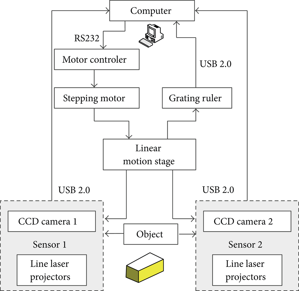
Block diagram of the system.
The measured object is placed on the glass platform, and the six laser projectors generate six distorted light stripes on the object surface, which contain the 3D characteristics information of the object surface since the stripes are modulated by the depth changing. Two CCD cameras capture the images of the distorted light stripes in two different angles. After calculating the 3D coordinates of points on the light stripes from the 2D images on the basis of parameters of cameras and light plane equations, the profiles of the six light plane sections can be obtained. During the measurement process, two sensors are driven by the stepping motor along one direction to scan the object at a certain speed; thus, a series of profiles can be acquired. At the same time, the separation distances between the profiles are read from the grating ruler. By building up the profiles according to the separation distances, the entire 3D surface of the measured object can be obtained.
3. Measurement Model
The measurement model of the MSSS is shown in Figure 3. The coordinate systems in Figure 3 are defined as follows: oc1 − xc1yc1zc1 is camera 1 coordinate system, oc2 − xc2yc2zc2 is camera 2 coordinate system, ou1 − xu1yu1 is nondistortion image coordinate system of camera 1, ou2 − xu2yu2 is nondistortion image coordinate system of camera 2, and o w − x w y w z w is world coordinate system. Those coordinate systems are relatively static during the scanning process. In addition, Om1 and Om2 are the principal points of the two cameras, π s l is the sth light plane in sensor 1, and π s r is the sth light plane in sensor 2. The following description only takes the light plane π1 l in sensor 1 as an example because the model of either sensor is similar.

The model of the MSSS scanning measurement system.
For any illuminated point P on the light stripe formed by light plane π1
l
and the object surface, its coordinate in o
w
− x
w
y
w
z
w
is denoted by

where
Point p on the image plane is the projection of P. The homogeneous coordinate of p in ou1 − xu1yu1 is denoted by

where
Real lenses do not satisfy the pinhole model and usually exhibit some degree of geometric distortion. Thus, considering the first two terms of the radial distortion for the camera lens, we have the following equations for each point in each image:

where
In camera 1 coordinate system, the space equation of light plane π1 l is described by
The measurement coordinate system o
m
− x
m
y
m
z
m
is established at the position of the world coordinate system where the first image is captured during the scanning process. It should be noted that the measurement coordinate system is fixed and does not move with the translation of the sensors. Since the sensors are moved linearly, the transformation relationship between the measurement coordinate system o
m
− x
m
y
m
z
m
and the world coordinate system o
w
− x
w
y
w
z
w
is only translation. Assume that the coordinate of point P in o
m
− x
m
y
m
z
m
is

where
Equations (1)–(5) are the complete measurement model of the system. In sensor 1, the 3D measurement coordinates
Get the image coordinates
Calculate the nondistortion image coordinate
Combine (2) and (4) to get the 3D coordinates in camera frame
Convert the camera coordinates to world coordinates
Transform the world coordinates
The 3D measurement coordinates of the illuminated points on the other light stripes can also be calculated by the same method.
4. Light Stripes Extraction and Arrangement
In the MSSS, the captured light stripes are usually not continuous, as shown in Figure 4(a), which is caused by the uneven surface and the irregular surface material. However, according to the measurement model, the 3D coordinates of the points on the light stripes can be correctly calculated as long as the points correspond to the light plane equation. Therefore, it is necessary to find the one-to-one correspondence relationship between the light stripes and the light. The best solution is to arrange the light stripes in an appropriate order. We divided the extraction and arrangement of light stripes into four steps.

Light stripes extraction and arrangement. (a) Image with light stripes. (b) Extracted light stripes. (c) Light stripes after disturbances elimination. (d) Linked light stripes. (e) Light stripes arrangement.
Firstly, extract light stripe, which means locating the center of the light stripe. We adopt a method presented by Steger [20]. For each pixel, the second order Taylor polynomial is computed by convolving the image with the derivatives of a Gaussian smoothing kernel. Line points are required to have a vanishing gradient and high curvature in the direction perpendicular to the line. The resulting filter generates a single response for each line. The line position can be determined with subpixel accuracy and the algorithm scales to lines with arbitrary width. The extracted results of light stripes are shown in Figure 4(b).
Secondly, eliminate the disturbances. The disturbances come from two aspects: one is the small thorns at the ends of the light stripes; the other is the short segment that is obviously out of the area covered by light stripes. Those disturbances can be eliminated easily by setting a threshold for the length of the light stripes. The length is calculated as the sum of the Euclidian distances between the successive points on light stripe as follows:

where
Thirdly, link the light stripes. The purpose of this step is to tie up the light stripes that belong to the same light plane and prepare for next arrangement. For any two light stripes in Figure 4(c), if the difference between the abscissas of endpoints is less than the preset threshold, the two light stripes can be linked. Figure 4(d) is the light linked stripes from Figure 4(c) and the preset threshold is 30. It should be noted that this step is just to tie up the light stripes that belong to the same light plane, instead of adding light points at the gaps.
Finally, arrange the linked light stripes. The arrangement principle is based on the distance between the straight line determined by the left edge of the image and the light stripes: the light stripe with shorter distance is more close to the left. The distance between a straight line and a light stripe is defined as the minimum of distances from the points on the light stripe to the line:

where
5. System Calibration
Calibration is the third major problem to be solved in MSSS. The parameters in the MSSS and their physical meanings are listed in Table 1 and all of them are determined by calibration.
System parameters.

5.1. Parameters of Camera and Light Plane Equations
The internal and external parameters of the two cameras can be calibrated by Zhang's method described in [21].
The calibration of light plane equation can be obtained by using a 2D planar target. Take sensor 1 as an example. The calibration model of line-structured-light sensor is shown in Figure 5. The world coordinate system o w − x w y w z w is established as shown in Figure 5: o w − x w y w is the target plane and the z component is 0. Light stripe L, projected as l in the image plane, is the intersection of the structured-light plane π1 l and the target plane.

Calibration model of line structured-light sensor.
Owing to the 2D projective transformation between the target plane and the image plane, the coordinates of the points on the image plane can be transformed from the coordinates of the points on the target plane through a 3 × 3 homography matrix:

where
Matrix
where
Since matrix
In summary, the camera coordinates of the points on the light stripe L can be obtained in the following three steps. Firstly, get the image coordinates of the feature points on the 2D planar target and calculate the homography matrix
After placing the planar target at several different positions, coordinates of a sufficiently large number of points in the camera coordinate system on the light plane π1 l can be calculated using the above method, after which the space equation of light plane π1 l can be fitted. Similarly, the space equations of the other light planes can also be obtained in the same way.
In practical, before calculating the space equation of light planes, the one-to-one corresponding relationship of the light planes and the straight light stripes in the images must be determined in advance. The simplest solution is to arrange the light stripes from left to right using the method described in Section 4.
5.2. Unit Translation Vector
As shown in Figure 6, the position of the world coordinate system is fixed while camera 1 is driven to move along the direction of the vector

Mathematical model of the sensor translation.
For a point F in the space, its world coordinates are denoted by

To facilitate the calculation, the world coordinate system origin
Above describes the process of obtaining 3D coordinates in the world coordinate system for sensor 1. The process for sensor 2 is similar. Therefore, merging left and right scanners’ 3D data is done by transforming them from camera 1 and camera 2 to the world coordinate system, respectively.
6. Experimental Results
6.1. System Calibration Setup
The MSSS is illustrated in Figure 7.
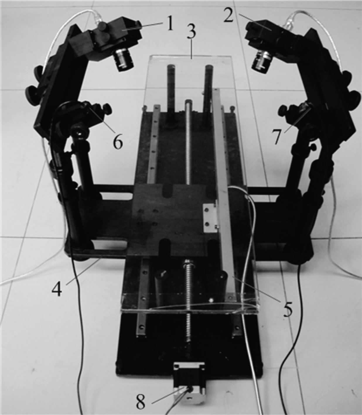
The conFiguration information of every part is listed in Table 2.
Configuration information of MSSS.

We designed a planar pattern with 10 × 11 circles for calibration, shown in Figure 8. The centers of the circles on the pattern are used as the calibration feature points. The diameter of the big circle is 15 mm and that of the small one is 9 mm. In the vertical direction, the distance between two adjacent centers is 15 mm, and the distance of two adjacent centers in the horizontal direction is 15 mm except that the fifth and the sixth column are 30 mm.

Target and the projected light stripes.
The system calibration process is as follows.
Place the planar pattern randomly at 10 positions within the FOV of each camera and each camera obtains an image at each position. Extract the image coordinates of the feature points on the pattern from the images. Then calibrate the internal parameters of the two cameras by Zhang's method.
Place the planar pattern at the public area in the FOV of the two cameras and two cameras obtain an image, respectively. Extract the image coordinates of the feature points on the pattern from the two images. Calibrate the camera external parameters by Zhang's method to obtain the rotation and translation relationship between the camera and the world coordinate systems.
Fix the pattern within the FOV of camera 1, start the stepping motor, and drive the sensors to move forward. Camera 1 captures an image before and after the movement, respectively. As the world coordinate system plane o
w
− x
w
y
w
coincides with the pattern plane, the location of the world coordinate system is fixed. Then calibrate the unit translation vector
Open the line-structured-light projectors, and project the planar lights on the pattern. Randomly move the pattern to three positions within the FOV of the two cameras, and each camera captures an image for each position. Calculate the camera coordinates of the points on the light stripe on the pattern. Fit the six light plane equations of the two sensors in each camera coordinate system according to the method described in Section 5.1.
6.2. Experimental Results
6.2.1. Calibration Results
The calibration results of the MSSS are shown in Table 3.
Calibration results of the MSSS scanning measurement system.

6.2.2. Accuracy Evaluation Results
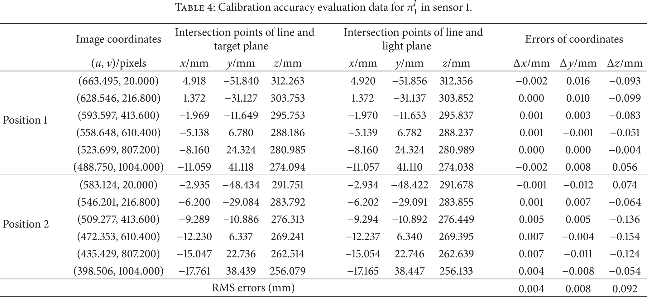
The line-structured-light sensor calibration accuracy is verified by comparing two values: one is the standard value, which is the camera coordinate of the intersection point of the ray Oc1p and the target plane, as shown in the Figure 5, and the other is the measured value, which is the camera coordinate of the intersection point of Oc1p and the light plane. Taking light plane π1 l for example, two of the images used for structured-light calibration are chosen to evaluate the sensor calibration accuracy. We selected six points on the light stripe in each image and evaluated the sensor calibration accuracy. The calibration accuracy evaluation data is shown in Table 4, which shows that the RMS errors in x, y, and z directions are 0.004 mm, 0.008 mm, and 0.092 mm, respectively.
Calibration accuracy evaluation data for π1 l in sensor 1.
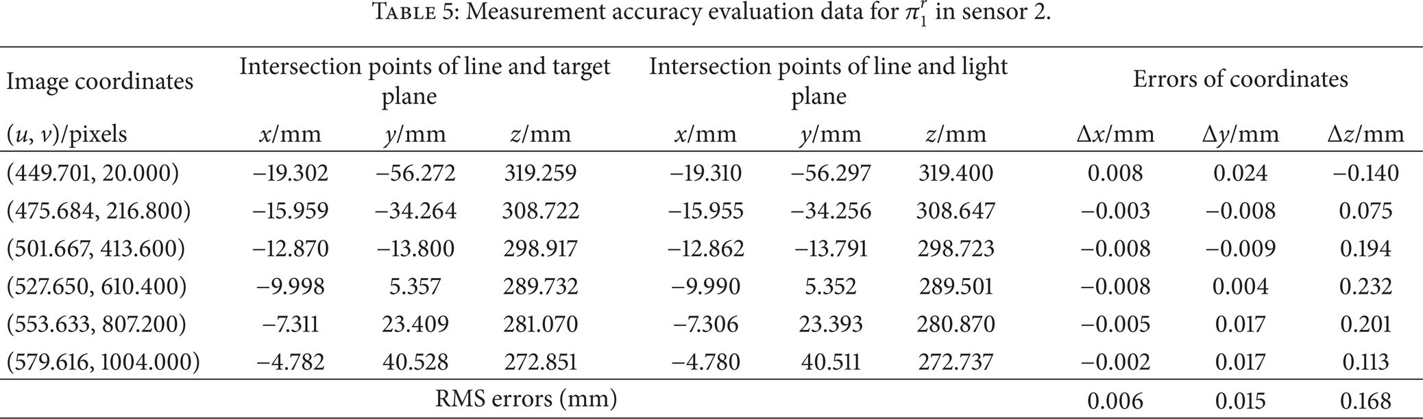
We placed the planar pattern at another random position, and calculate the errors of the light plane π1 r of the calibrated system in the same way. Those data can serve as the evaluation for sensor measurement accuracy since they are not involved in calibration process. The RMS errors for the system measurement accuracy in each axis are RMSx = 0.006 mm, RMSy = 0.015 mm, and RMSz = 0.168 mm, as shown in Table 5.
Measurement accuracy evaluation data for π1 r in sensor 2.
6.3. Measurement Results
A mouse is scanned by the MSSS to demonstrate the applicability. Figures 9(a) and 9(b) show the captured mouse image pair with light stripes projected on. From Figures 9(a) and 9(b), we can see, with single sensor, that there is blind area, where 3D coordinates are unable to obtain. The whole mouse is covered when 2 sensors are adopted, complementing each other's blind area. Figure 9(c) shows the 3D scanning result of the mouse, in which the scanning speeding is 7 mm/s and the time consumption is 16 seconds. Compared to the existing single or double structured-light 3D surface measurement system, our MSSS greatly improved scanning efficiency and obtained richer 3D surface data at the same scanning speeding and time consumption. In order to compare with the single line scan method, we used only one laser generator in each sensor. Figures 10(a) and 10(b) show the single stripe image captured by cameras 1 and 2, respectively, and Figure 10(c) shows the 3D reconstruction results. Note that here we use the same scan speed and frame rate for both multiline and single-line experiments. Because, with the same scan speed and frame rate, multiline approach provides more features in one frame than that of single-line approach; therefore, it gains richer information of the target.

Measurement experiment of a mouse. (a) Light stripe image of the mouse captured by sensor 1. (b) Light stripe image of the mouse captured by sensor 2. (c) 3D reconstruction results of the mouse.

Comparison experiment using single scan line. (a) Single stripe image of the mouse captured by camera 1. (b) Single stripe image of the mouse captured by camera 2. (c) 3D reconstruction results of the mouse.
7. Conclusions
A novel approach is presented to capture the 3D surface based on multiline structured-light sensors. There are three superiorities for this method compared with the existing methods.
The disadvantages of single structured-light 3D surface measurement system are overcome, such as limited measurement range, blind measurement area, and low scanning efficiency.
The mathematical model of the MSSS is established without particular spatial relationship, making the system easy to implement.
The system calibration is completed by a 2D planar pattern. It does not require complex calibration patterns or high-precision auxiliary equipment, which reduces the difficulty of the system calibration and ensures the measurement accuracy simultaneously.
In addition, note that the method proposed in this paper is not only applicable for the multi-line structured-light sensor with three light stripes, but also suitable for the sensor with more light stripes, which can further improve the scanning efficiency.
Conflict of Interests
The authors declare that there is no conflict of interests regarding the publication of this paper.
Footnotes
Acknowledgment
This work was supported by National Natural Science Foundation of China (no. 61072134).